Lecture 4
Resultant
The properties of force, moment, and couple were developed in the previous four lecture. Now we
are ready to describe the resultant action of a group or system of forces. Most problems in mechanics deal
with a system of forces, and it is usually necessary to reduced the system to its simplest form to describe
its action. The .resultant of a system of forces is the simplest force combination which can replace the
original forces without altering the external effect on the rigid body to which the forces are applied.
Equilibrium of a body is the condition in which the resultant of all forces acting on the body is zero. This
condition is studied in statics. When the resultant of all forces on a body is not zero, the acceleration of
the body is obtained by equating the force resultant to the product of the mass and acceleration of the
body. This condition is studied in dynamics. Thus, the determination of resultants is basic to both statics
and dynamics
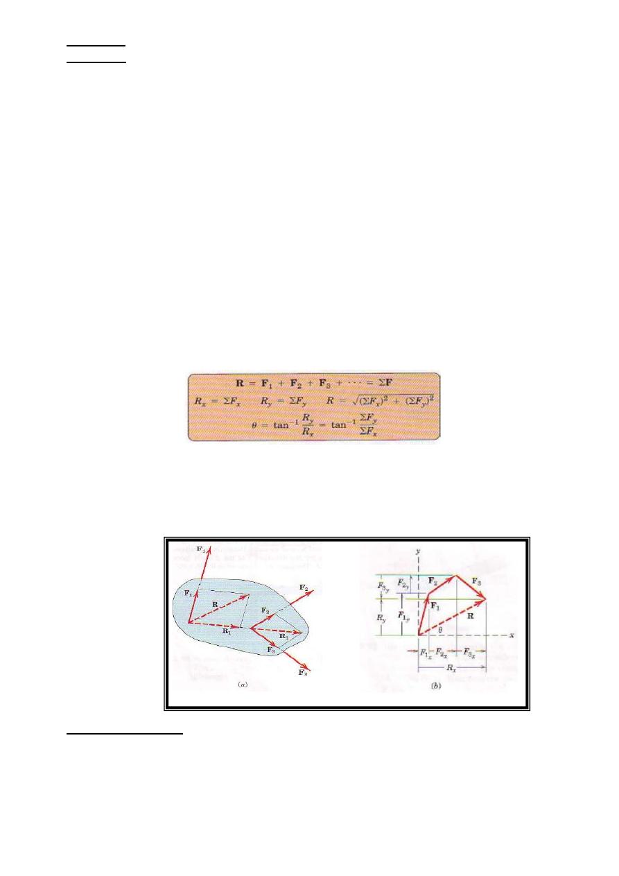
The most common type of force system occurs when the forces all act in a single plane, say, the
x-y plane, as illustrated by the system of three forces F1, F2, and F3 in Fig. 1. We obtain the magnitude
and direction of the resultant force R by forming the force polygon shown in part b of the figure, where
the forces are added head to-tail in any sequence. Thus, for any system of coplanar forces we may write
Graphically, the correct line of action of R may be obtained bv preserving the correct lines of action of
the forces and adding them by the parallelogram law. We see this in part a of the figure for the case of
three forces where the sum R1 of F2 and F3 is added to F1 to obtain R. The principle of transmissibility
has been used in this process.
Figure 1
Algebraic. Method
We can use algebra to obtain the resultant force and its line of action
1. Choose a convenient reference point and move all forces to that point. This process is depicted for a
three-force system in Figs.2a and b, where M1, M2, and M3 are the couples resulting from the transfer of
forces F1, F2, and F3 from their respective original lines of action to lines of action through point O.
26
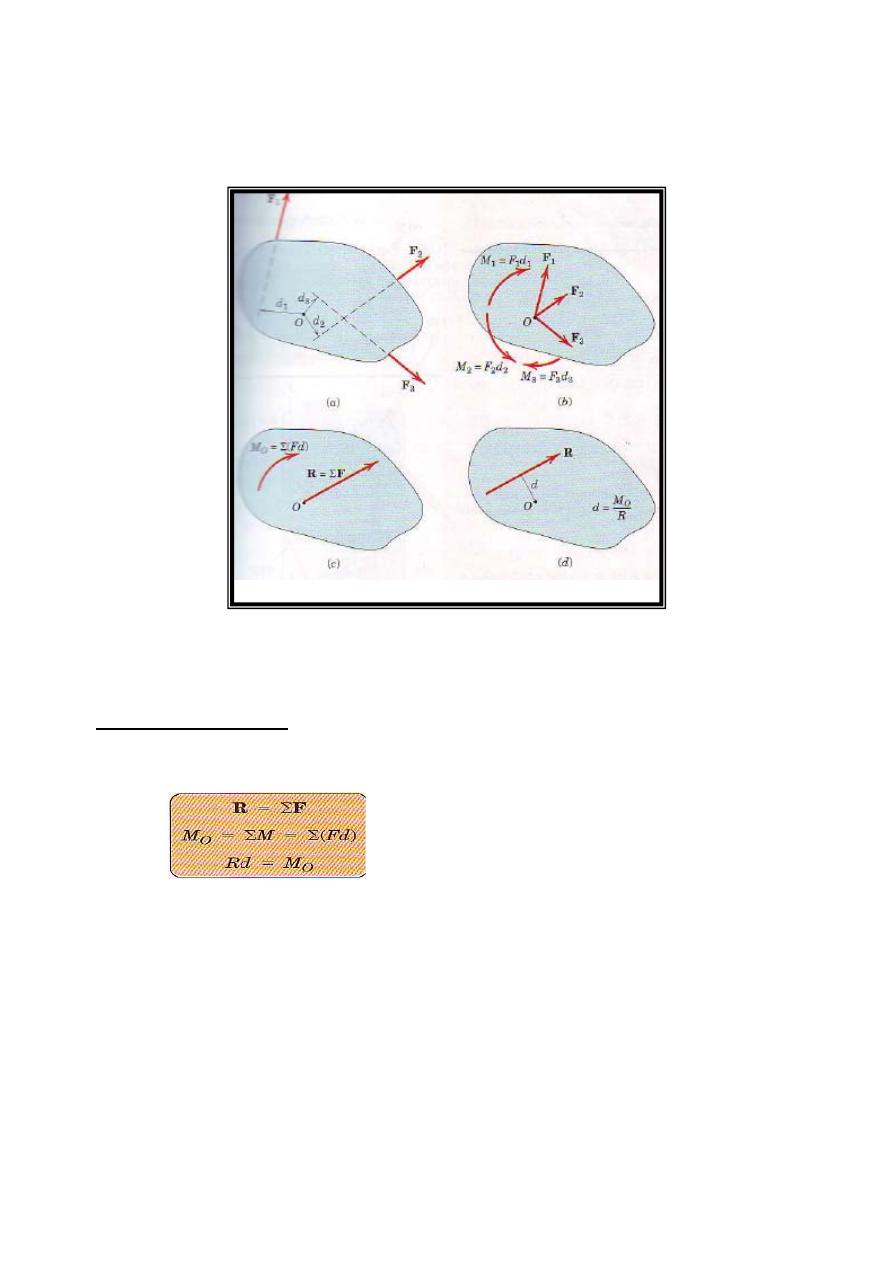
2. Add all forces at O to form the resultant force R, and add all couples to form the resultant couple Mo.
We now have the single force-couple system, as shown in Fig. 2c.
3. In Fig. 2d, find the line of action of R by requiring R to have a moment of Mo about point O. Note that
the force systems of Figs.2a and ,2d. are equivalent, and that Σ(Fd) in Fig. 2a is equal to Rd in Fig. 2d
Figure 2
principle of Moments
This process is summarized in equation form by
……….2
The first two of Eqs.2 reduce a given system of forces to a force- couple system at an arbitrarily chosen
but convenient point O. The last equation specifies the distance d from point O to the line of action of R,
and states that the moment of the resultant force about any point O equals the sum of the moments of the
original forces of the system about the same point. This extends Varignon's theorem to the case of
nonconcurrent force system; we call this extension the principle of moments . for a concurrent system of
forces where the lines of action of all forces pass through a common point O, the moment sum ΣMo about
that point is zero. Thus, the line of action of the resultant R = ΣF, determined by the first of Eqs. 2, passes
though point O. For a parallel force system, select a coordinate axis in the direction of the forces. If the
resultant force R for a given force system is zero, the resultant of the system need not be zero because the
27
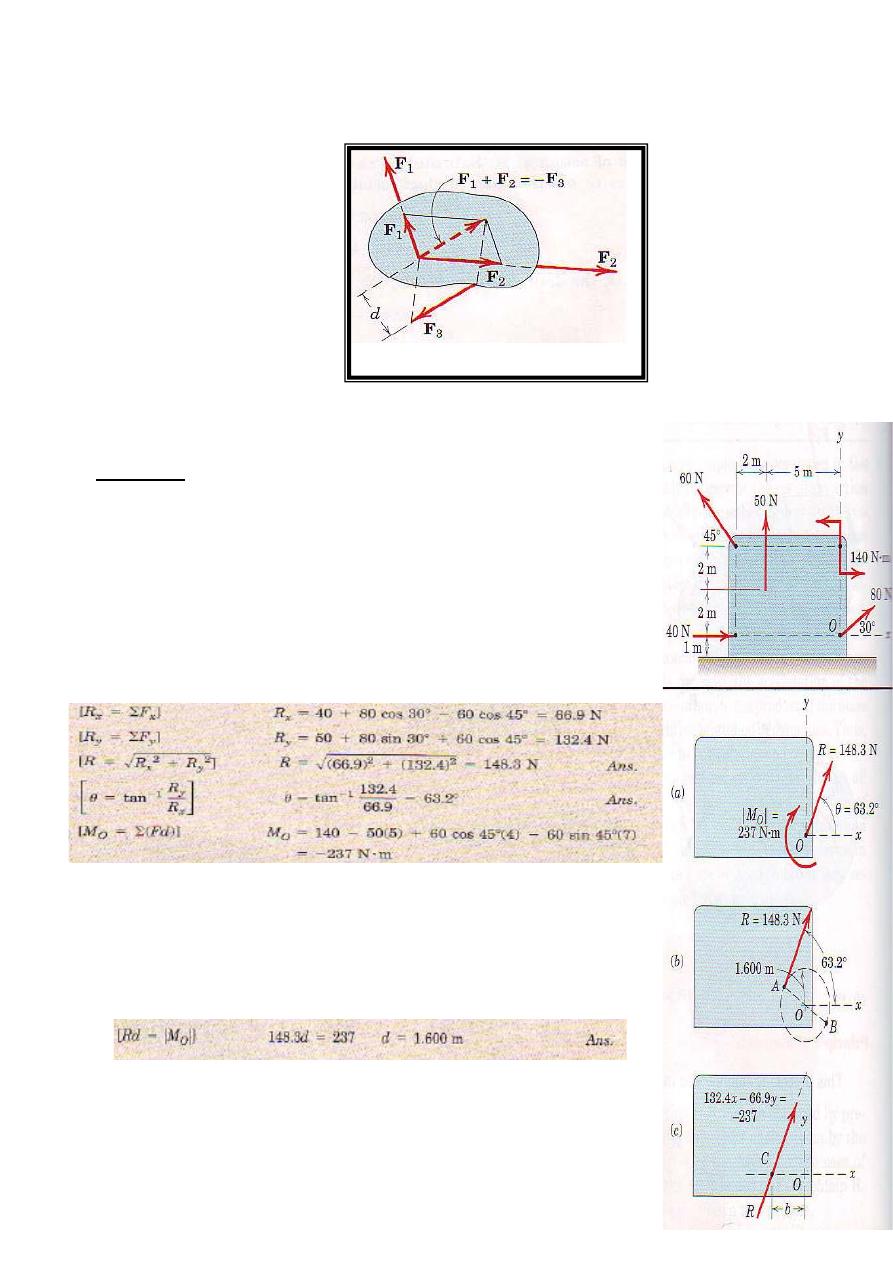
resultant may be a couple. The three forces in Fig. 3, for instance, have a zero resultant force but have a
resultant clockwise couple M=F3d
Figure 3
Examples
Example1
Determine the resultant of the four forces and one couple which act on the
plate shown.
Solution
Point 0 is selected as a convenient reference point for the force-couple
system that is to represent the given system
The force-couple system consisting of R and Mo is shown in Fig.a
We now determine the final line of action of R such that R alone
represents the original system
Hence, the resultant R may be applied at point on the line which makes a
63.2˚ angle with the x-axis and is tangent at point A to a circle of 1.6m
radius with center 0, as shown in part b of the figure. We apply the equation
28
Rd=Mo in an absolute-value sense (ignoring any sign of Mo) and let the physics of the situation, as
depicted in Fig.a, dictate the final placement of R. had Mo been counterclockwise, the correct line of
action of R would have been the tangent at point B.
The resultant R may also be located by determining its intercept distance b to point C on the x-
axis, Fig.c. with R
x
and R
y
acting through point C, only R
y
exerts a moment about 0 so that
Alternatively, the y-intercept could have been obtained by noting that the moment about 0 would be due
to R
x
only.
Example 2
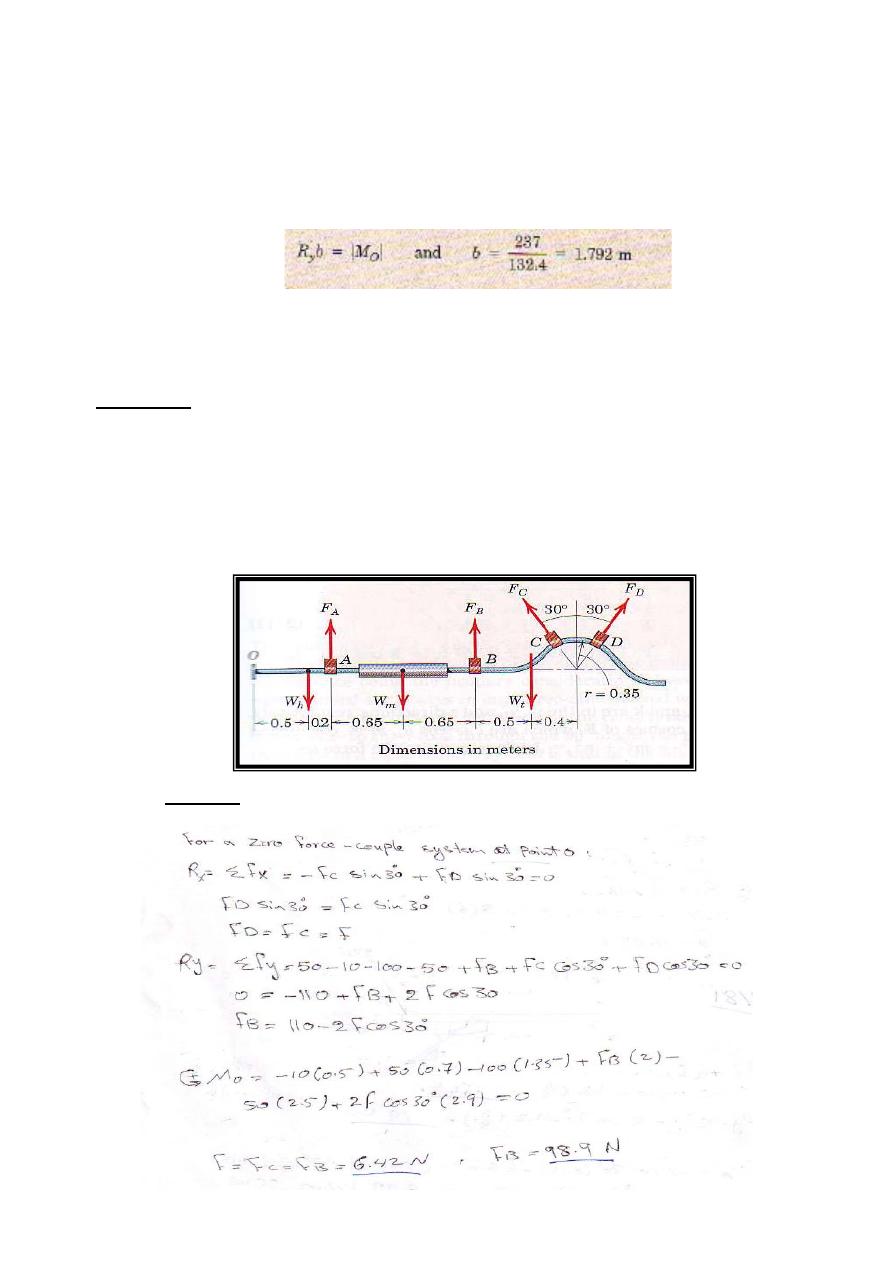
An exhaust system for pickup truck is shown in the Figure. The weights W
h
, W
m, and
W
t
of the headpipe,
muffler, and tajlpipe are 10, 100. and 50 N, respectively, and act at the indicated points. If the exhaust
pipe hanger at point A is adjusted so that its tension F
A
is 50 N, determine the required forces in the
hangers at points B, C, and D so that the force couple system at point O is zero. Why is a zero force
couple system at O desirable?
Solution
29
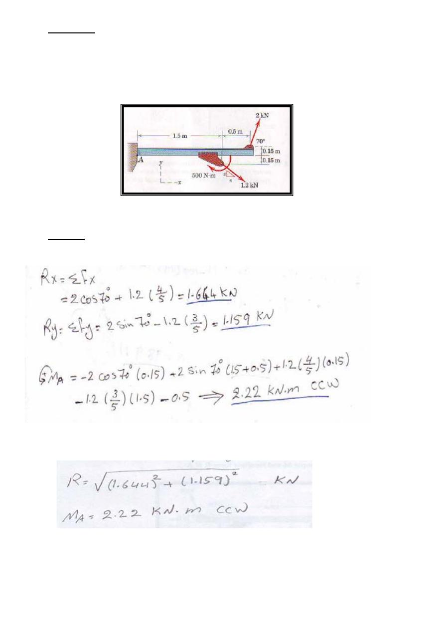
Example 3
The flanged steel cantilever beam with riveted bracket is subjected to the couple and two forces shown,
and their effect on the design of the attachment at A must be determined. Replace the two forces and
couple by an equivalent couple M and resultant force R at A
Solution
The force –couple system is
30
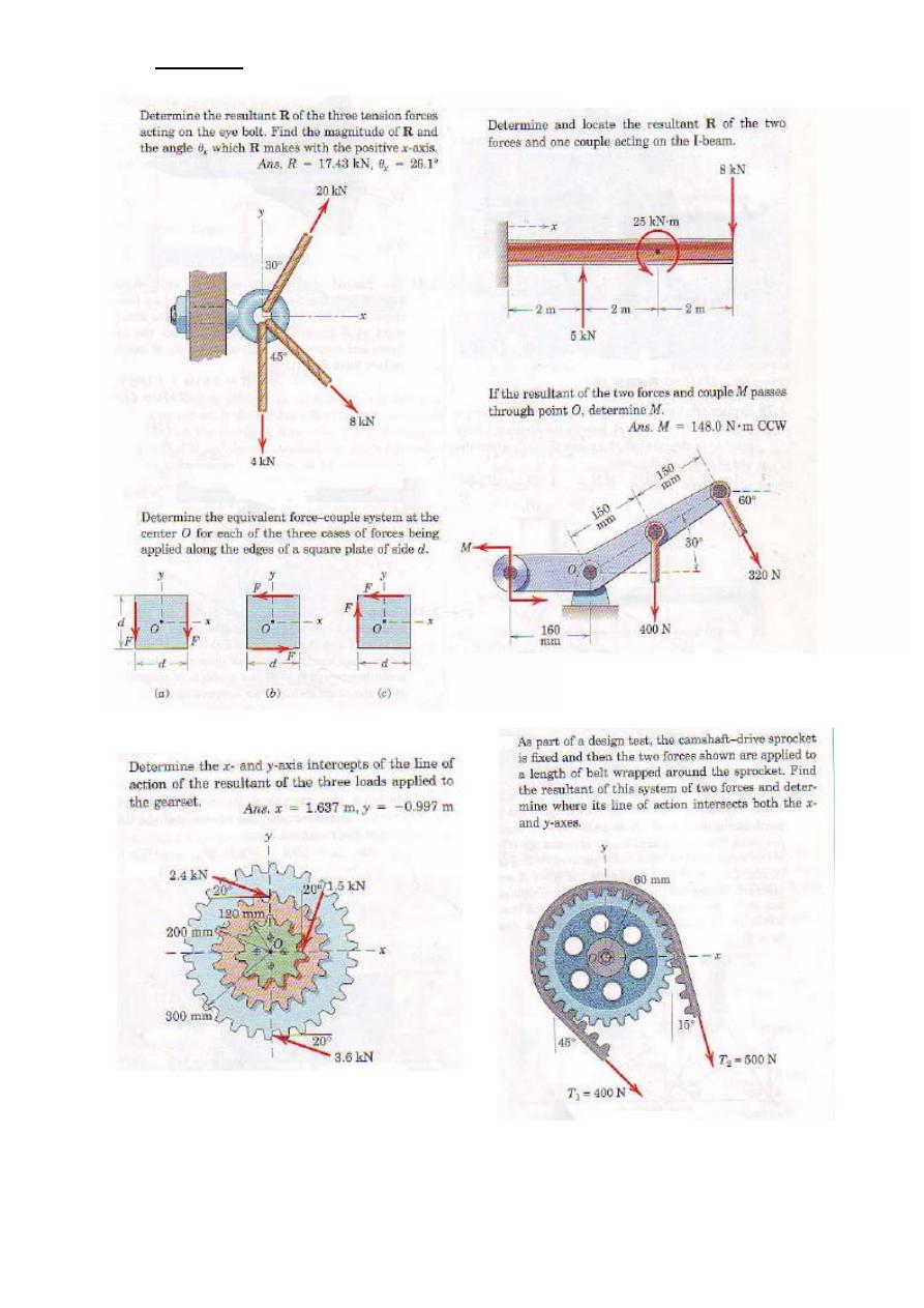
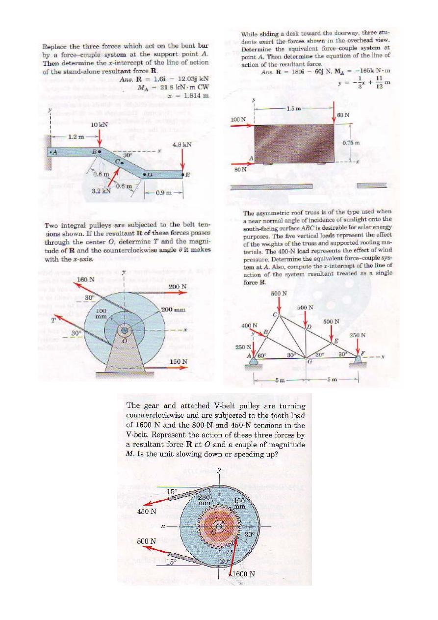
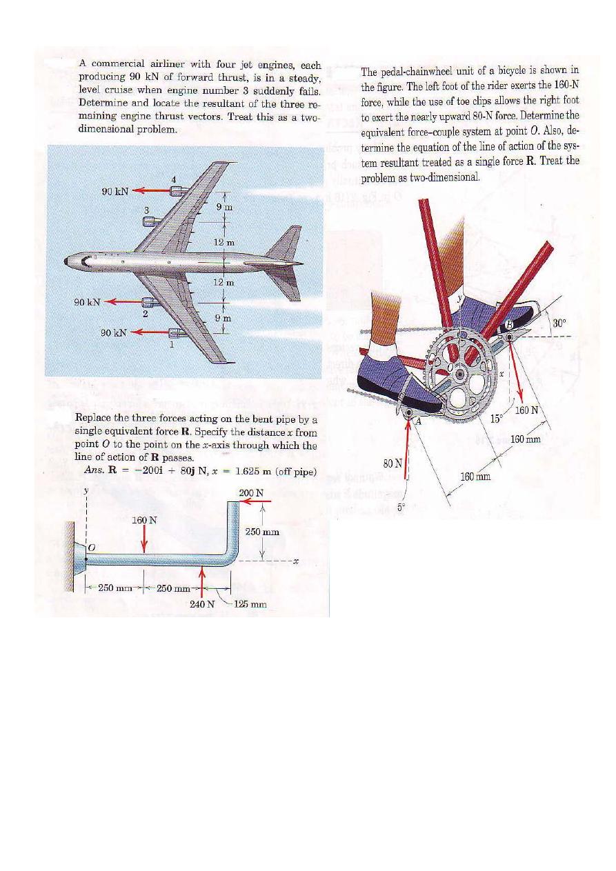
Problems
31
32
33