
SPICE / MultiSim Tutorial
1. Introduction
Cellular phones and computers are just two examples of some of today's extremely
complex electronic systems. Such devices contain millions of circuit components, and
simple trial and error is not an effective way of ensuring that the final product will work
properly. As a result, designers often use circuit simulators to verify the performance of
a circuit before fabrication.
The most popular component level circuit simulator available today is called SPICE
(Simulation Program with Integrated Circuit Emphasis), which was developed here at the
University of California, Berkeley, in the 1970s under the guidance of Prof. Pederson.
Today vendors offer many different versions of SPICE that differ mainly in the user
interface but are internally very similar to the original “Berkeley SPICE”. This tutorial
introduces a version of SPICE called MultiSim.
Circuit simulation with SPICE (and MultiSim) involves two steps:
(1) Enter in the circuit schematic (with MultiSim's graphical user interface).
(2) Choose the type of analysis and run the simulation.
2. Organization of this Tutorial
1. Introduction
2. Organization
I Basic Circuit Simulation Techniques in MultiSim
3. MultiSim Environment
4. Schematic Capture of an Example Circuit
5. Simulation and Results Display
II Alternative Forms of Circuit Simulation in MultiSim.
6. Simulated Instruments
7. Using the Breadboard Tool
8. Conclusion
Notes about this Tutorial:
• Before running a simulation, you should always have a general understanding of
how your circuit works.
• In this document,
Boldface black
refers to actions you perform on the computer.
Example:
Click
on the
menu item.
3. MultiSim Environment
1. First, you need to log into a lab machine to use MultSim. Ask the TA in-charge for
login information. You may also be able to use MultiSim by logging in remotely.
2. Once logged in,
Double-click
on the
icon on the desktop. If a window appears
with “Evaluation License” written in the middle of it,
click
the Evaluate button. After
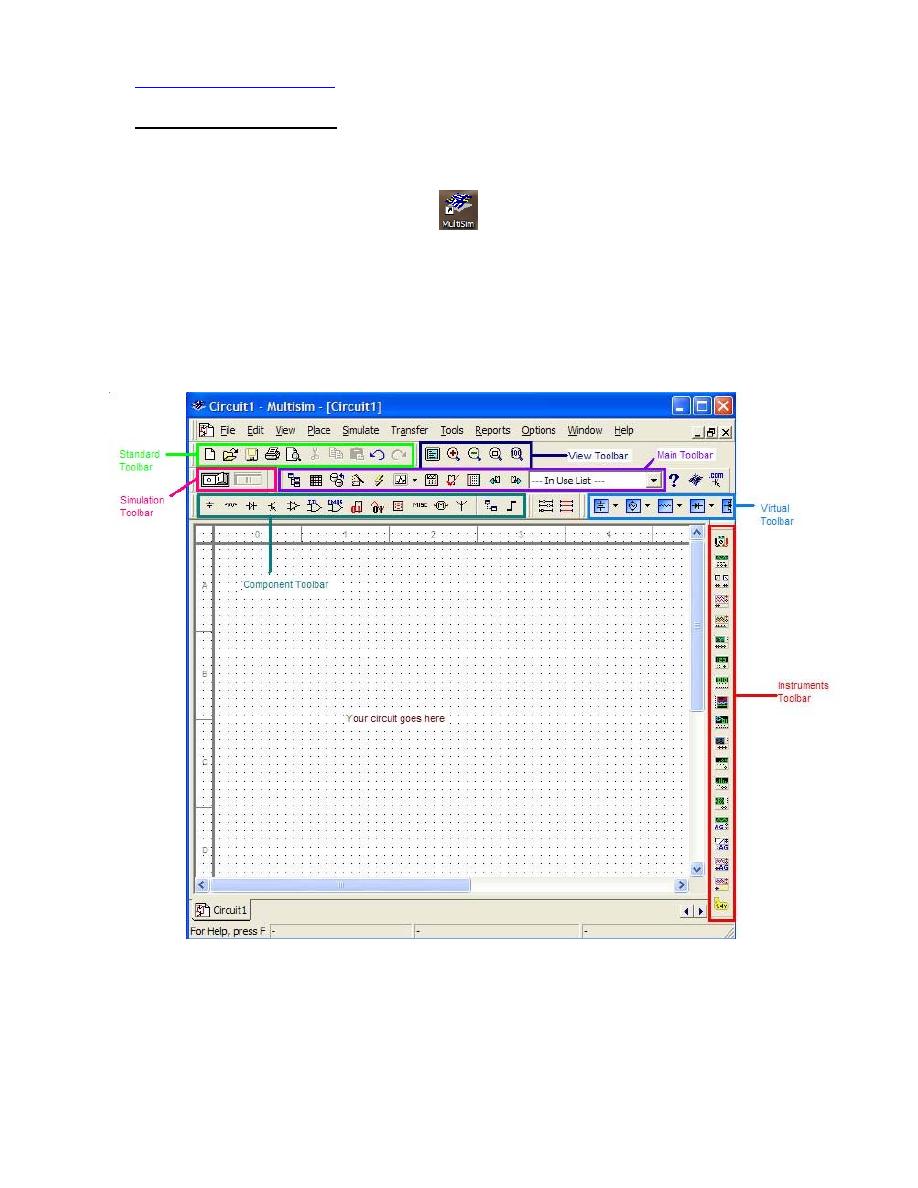
MultiSim finishes loading, you should see the screen shown below in Figure 1. This
is called “Capture and Simulate” environment because you “Capture” your schematic
by drawing it in MultiSim and then you “Simulate” it.
Figure 1 also shows the different parts of the MultiSim workspace; the location of the
toolbars in your MultiSim window may be different.
Figure 1 The most important components in the MultiSim workspace
The purpose of each toolbar will become clear as you move through this document.
If you don’t see the toolbars shown above,
click
on the View menu and go to
Toolbars. Make sure that you at least have the toolbars shown in Figure 2 checked.
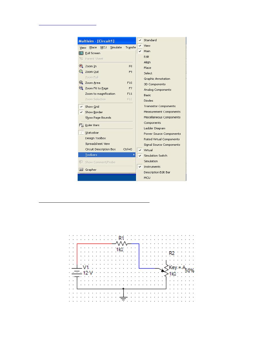
Figure 2 Viewing the toolbars
4. Schematic Capture (Entering a Simple Circuit)
To begin, let’s construct the simple circuit shown below in Error! Reference source not
found.. This circuit is composed of a voltage source (battery), a resistor, and a
potentiometer (variable resistor).
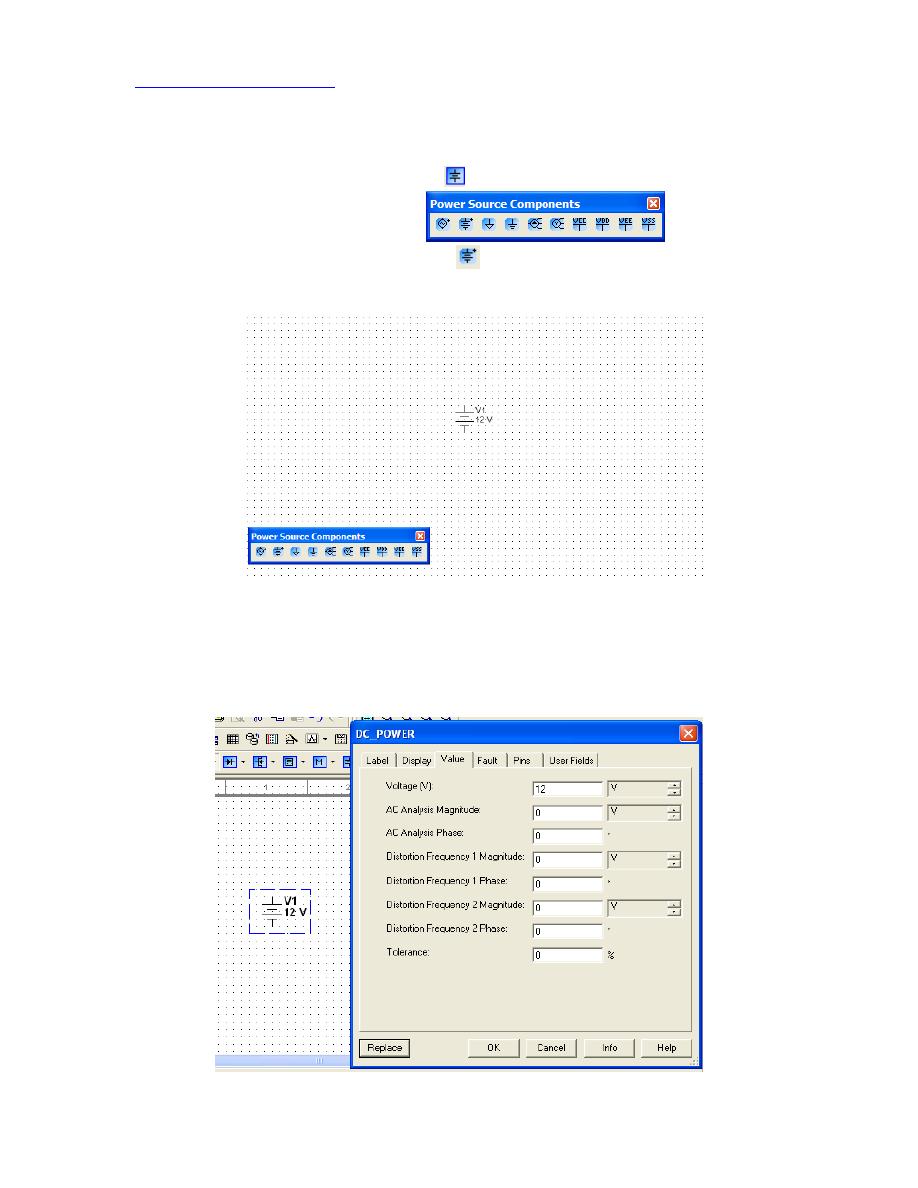
Figure 3 A simple circuit captured in MultiSim
I Adding the Voltage Source (Battery):
1.
Click
on the Power Source Family
in the
Virtual Toolbar
.
2. The Power Source Components
will pop up.
3.
Click
on the DC Power Source icon
and then
click
on the workspace to place
a battery. Error! Reference source not found. shows the result.
Figure 4 A DC power source in MultiSim
To change the value of the power source,
Double-click
the battery. This opens up the
Power_Sources dialog box shown below. Make sure that the voltage is set to 12 V and
then press OK.
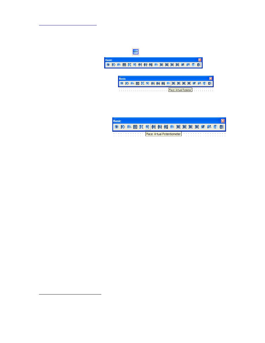
Figure 5 Power Sources Dialog box. Use this to change the value of the battery voltage.
II Adding the Resistor and the Potentiometer
4.
Click
the Basic Components Family
in the
Virtual Toolbar
.
5. The Basic Components
will pop
up.
6.
Click
on the Virtual
1
Resistor
tool
and drag a resistor onto the workspace. Like the battery, you can
double-click
the resistor to change its properties.
7. Lastly, we must add the potentiometer. In the Basic Components window,
click
on the Potentiometer Tool
and drag a potentiometer onto the workspace. You can increase/decrease the
resistance on the potentiometer by pressing ‘a’ / ‘Shift+a’ on the keyboard. The
increase and decrease refers to the resistance between the middle leg and the
bottom leg of the potentiometer. You can also
double-click
the potentiometer to
open its properties and change the total resistance of the potentiometer or its
increment / decrement value.
Error! Reference source not found. shows the circuit components placed on your
workspace. The “50%” next to the potentiometer means that the resistance between the
middle leg and bottom leg is 50% of 1 kΩ: 500 Ω. If you press ‘a’, the resistance will
increase by 5% (the resistance between the middle leg and the top leg will decrease by
5%). Again, you can
Double-click
the potentiometer to change the increment
percentage. If you move your mouse over the potentiometer, you can also use the slider
that appears to change its resistance.
1
MultiSim distinguishes “Virtual” components from “Real” components. With real components, you place
a part that has the actual shape of the real component, not a schematic symbol. You will see examples of
this in Section 8.
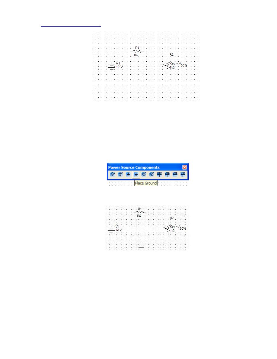
Figure 6 The circuit components are in place
III Adding the Ground
8. The final component to add is the ground. You cannot simulate the circuit without
a ground, because SPICE (the underlying simulation engine) uses nodal analysis
to solve circuits. The first step in nodal analysis is to pick a ground node. It does
not matter where we ground the circuit, but for consistency, let's pick the node at
the bottom of the circuit as ground.
9.
Click
the Ground tool
in the Power Source
Components menu. Drag the ground to the bottom of the circuit, the result is
shown in Error! Reference source not found..
Figure 7 Circuit ready for wiring
10. Connections are placed by clicking on the terminal of the first component,
moving the cursor the the target, and clicking again. Error! Reference source
not found. shows the results of wiring the 12 V source to the 1 kΩ resistor.
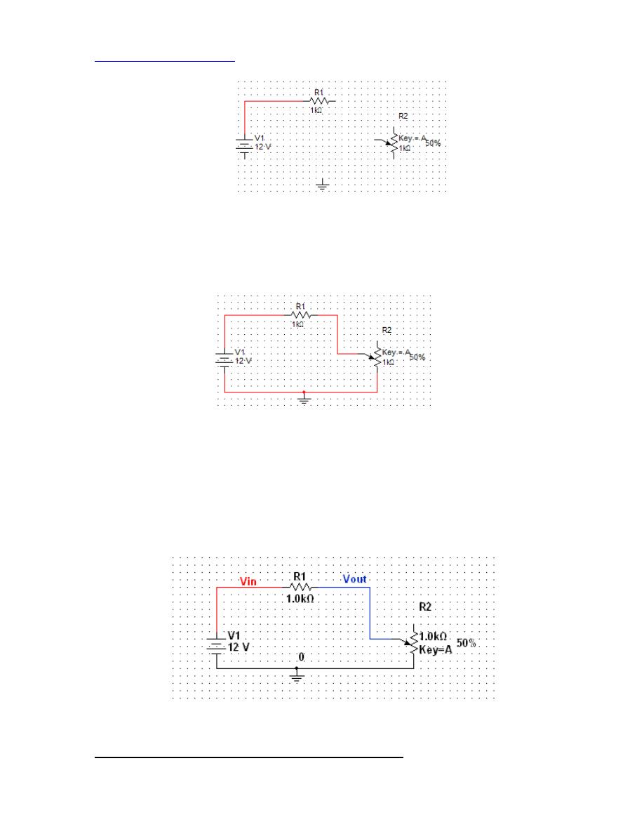
Figure 8 A wire connects the 12 V source to the 1 kΩ resistor
Complete the wiring as shown in Error! Reference source not found.. Make
sure you connect the wire from the 1 kOhm resistor to the wiper of the
potentiometer.
Figure 9 The wired circuit
To simplify debugging especially of larger circuits you can give the signals
intuitive names, such as “Vin” and “Vout” and assign different colors to wires
(e.g. red for power and black for ground). To do so
right-click
the wire and
choose property. Type in the wire name and
click
the show box.
Right-click
the
wire again and choose “Segment Color”. Choose a color and press OK. Change
the wire colors and add intuitive wire names as shown in Figure 10 below.
Figure 10 The circuit is ready for simulation
6. Running the Simulation and Using the Results Display
We are now ready to simulate our circuit. In the laboratory, you would now turn on the
power use lab instruments, such as the multimeter and oscilloscope, to check voltages
and currents in your circuit. Circuit simulators are much faster at finding the same result.
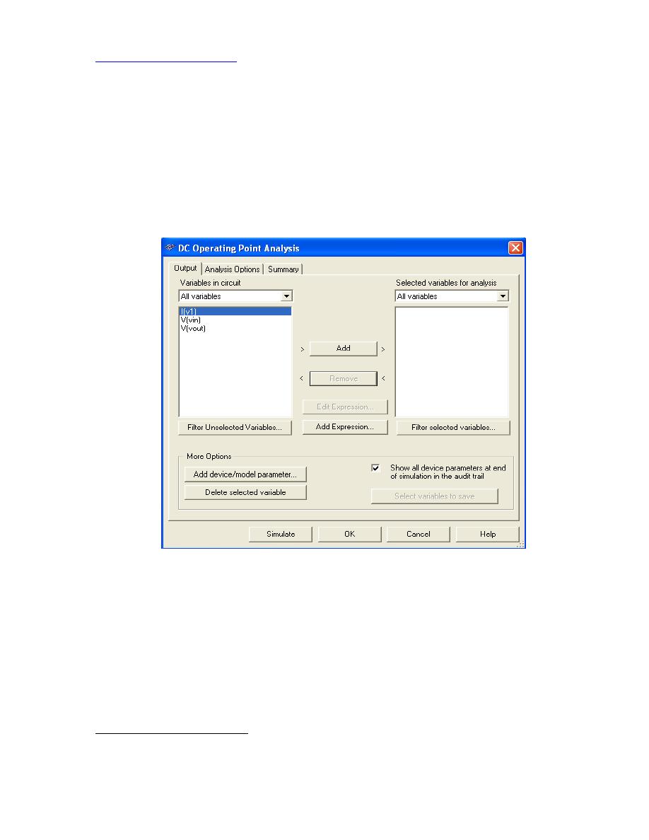
From the
Simulate
menu, choose
AnalysesÆDC Operating Point ….
The DC
Operating Point Analysis window should pop up (Error! Reference source not found.).
Next you choose circuit variables for analysis. V(vin) and V(vout) are the voltages and
wire names you have given, and I(v1) is the current though the voltage supply
2
. Add all
three variables to the panel on the right. More complex circuits have many more
variables; in which case you would only choose the ones you are interested in.
Figure 11 DC Operating Point Analysis Window
Click
the “Simulate” button to perform the simulation. The window shown in Error!
Reference source not found. appears with the results. With an input voltage of 12 V and
the potentiometer set at 50% (500
Ω), Vout is 4 V as expected. The current resulting from
placing 12 V across a total resistance of 1.5k
Ω is 8mA, which we can easily verify with
Ohm’s Law (V = IR). Since SPICE defines the current flowing into the positive terminal
of the source as positive but the current actually runs in the opposite direction, it reports
the result as a negative number. Play with the results by changing the resistance of the
potentiometer by selecting it and pressing the “a” or “Shift-a” keys and rerunning the
simulation.
2
Voltage sources set to V=0 are the easiest way for determining branch current with SPICE (e.g.
MultiSim).
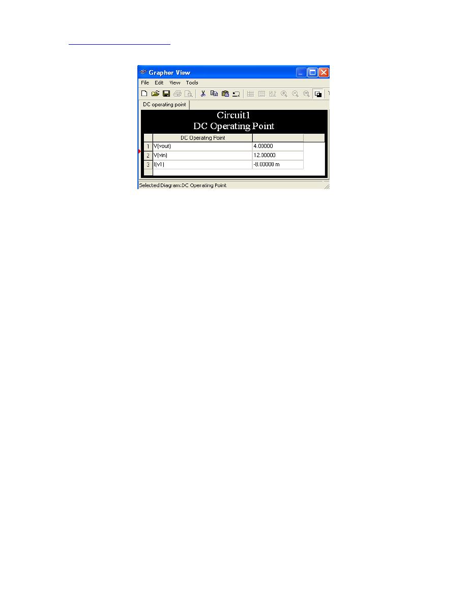
Figure 12 Simulation result for the DC operating point analysis
Analysis of Changing Signals
Most circuits deal with signals that are changing. SPICE offers three principal analyses
for this purpose:
1. DC Sweep
2. Transient Analysis
3. AC Analysis
We will run each type of analysis on our sample circuit. These forms of analysis will
appear throughout EE100 and other electronic circuit courses and laboratories.
DC Sweep
Choose
SimulateÆAnalysesÆDC Sweep
and change the parameters so that they
match the values in Error! Reference source not found..
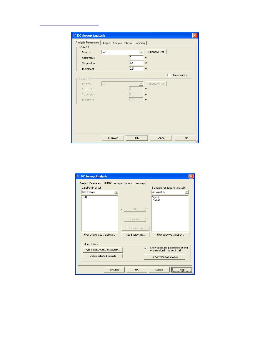
Figure 13 Analysis Parameters for DC sweep analysis
Then
click
on the Output tab and add V(vin) and V(vout) to the ‘Selected Variables for
Analysis’ box as shown in Figure 14
Figure 14 Analysis Parameters for DC sweep analysis
Finally,
click
the Simulate button to obtain the results shown in Figure 15.
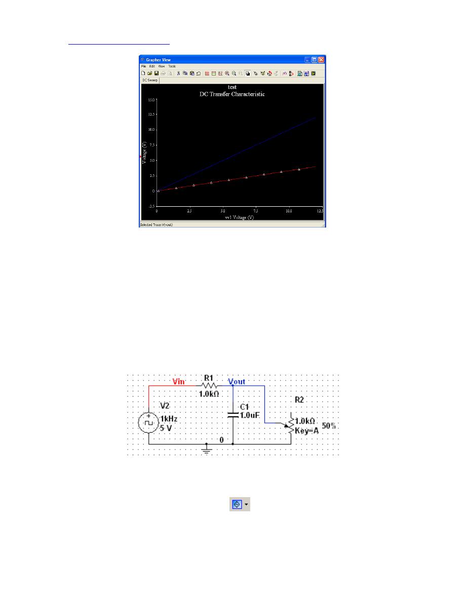
Figure 15 Result of DC sweep analysis
Can you find what percentage the potentiometer has been set to? Check your answer by
running a simulation!
In the laboratory we can perform a DC analysis by repeatedly adjusting the input of the
circuit and then measuring the output with the DMM. What a pain. Isn't MultiSim
AWESOME!
Transient Analysis
Transient analysis evaluates how signals change over time. In the laboratory, you can
examine this behavior with an oscilloscope. Figure 16 shows the circuit prepared for
transient simulation.
Figure 16 Modified circuit for transient analysis
The voltage source has been replaced with a “Clock Voltage Source” (which can be
found under the Signal Source Components
button as shown in Figure 17).
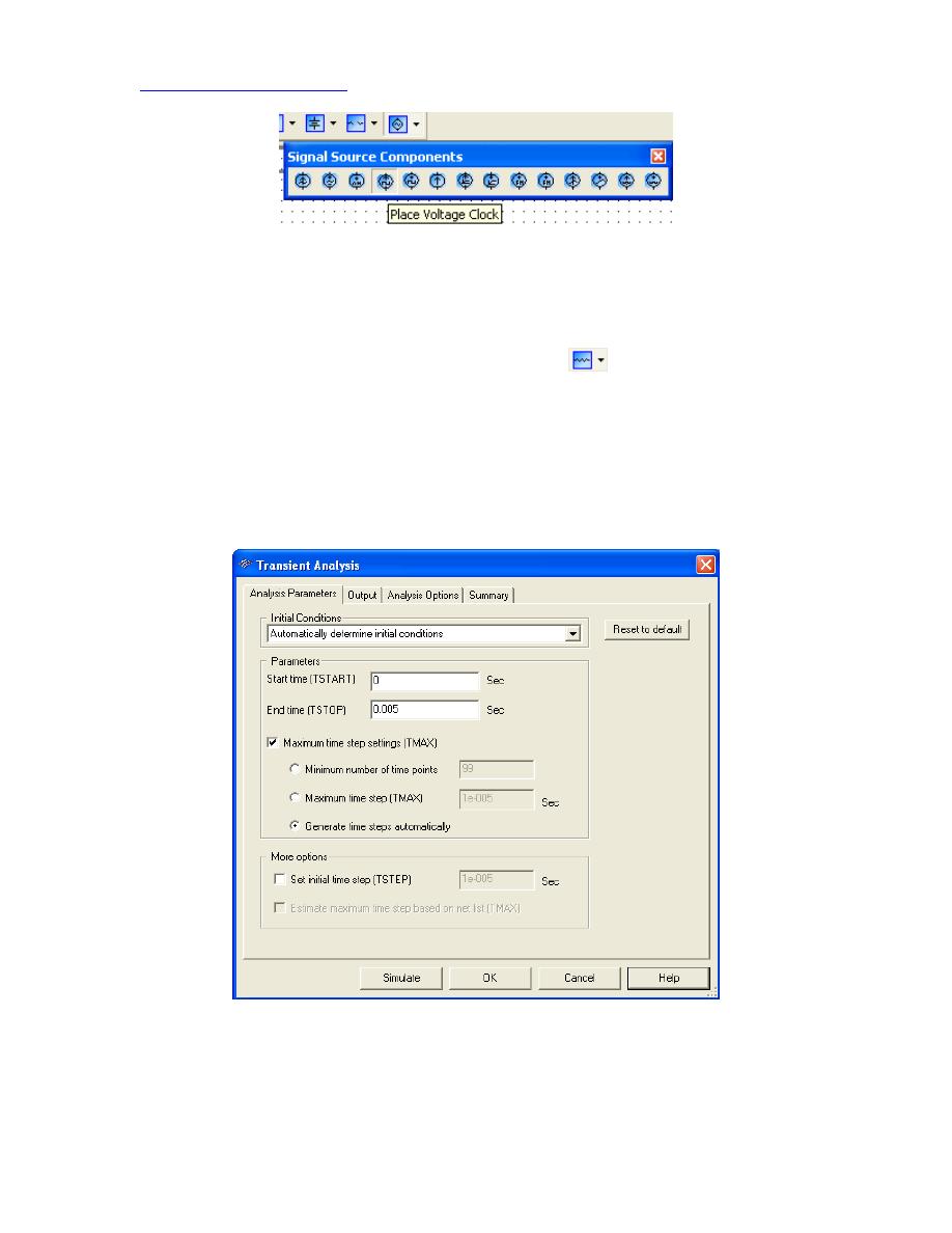
Figure 17 Adding the Clock Voltage Source
Double-click
the clock voltage source and make sure that the voltage is set to 5 V and
that the frequency is set to 1 kHz.
The capacitor C1 (which can be found under the Basic
button) has been added to
make the circuit more interesting for transient analysis. You can rotate the capacitor by
Right-clicking
it and selecting ‘90
o
Clockwise’ or ‘90
o
CounterCW’.
Next, choose
SimulateÆAnalysesÆTransient Analysis…
and use the parameters
from Figure 18. Make sure that V(vin) and V(vout) are in the ‘Selected variables for
analysis’ box under the Output tab.
Click
the Simulate button! The simulation results
should match those shown in Error! Reference source not found.9.
Figure 17 Transient analysis parameters
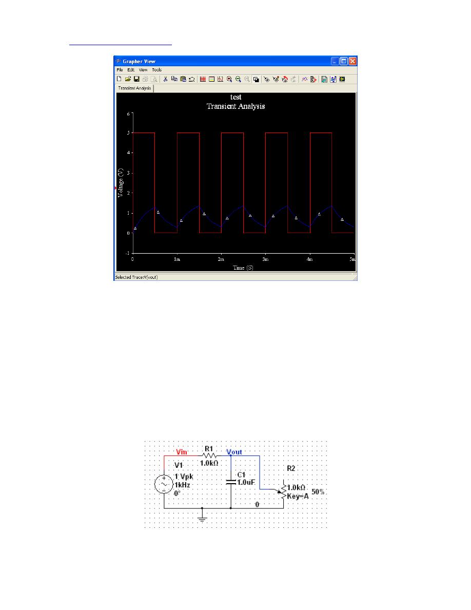
Figure 18 Transient analysis results
AC-Analysis
The AC-analysis directly computes the frequency response of a circuit and draws the
Bode Plot (you may want to revisit this section later if Bode Plots have not been covered
yet in the lecture). Error! Reference source not found.9 shows the sample circuit
prepared for AC analysis. Notice that the clock voltage source has now been replaced by
an AC voltage source. Like the clock voltage source, this can be found in the Signal
Source Components Group.
Next, choose
SimulateÆAnalysesÆAC Analysis…
and use the parameters from Figure
20. Make sure that only V(vout) are in the ‘Selected variables for analysis’ box under the
Output tab.
Click
the Simulate button! The simulation results should match those shown
in Figure 21.
Figure 19 Circuit for AC analysis
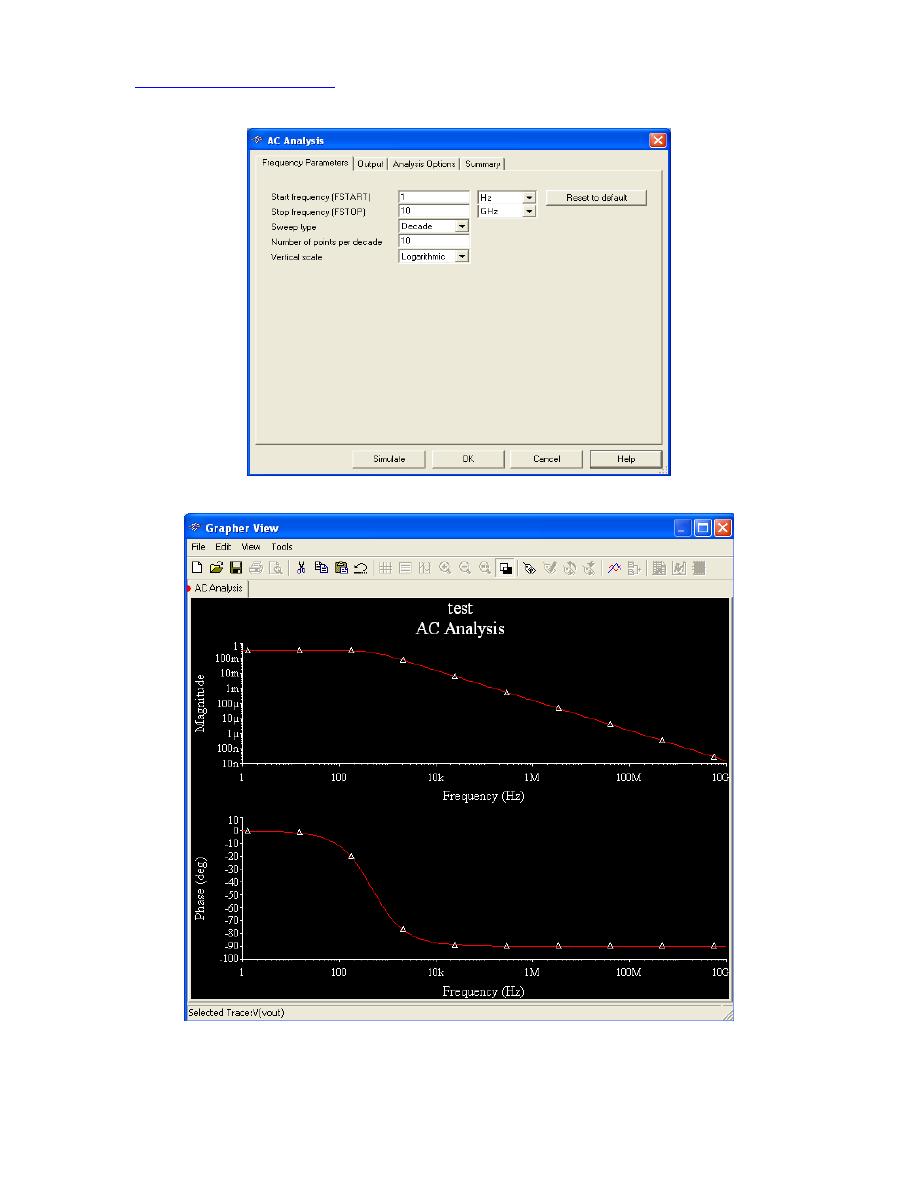
Figure 20 AC analysis simulation parameters
Figure 21 AC analysis simulation results for V
out
II Alternative Ways of Circuit Simulation in MultiSim
7. Simulated Instruments
This section describes an alternative way to perform simulations with MultiSim that more
closely resembles what you would do in the laboratory. Although this procedure may be
more intuitive at first, similar to real lab work, it generally takes more time than the
simulation approach described in Section 6.
This method involves using virtual instruments created in MultiSim that look and work
just like those in the laboratory. To take any measurements from a simulation, we first
need to add instruments. Hence your simulation environment is a step closer to your real
lab environment.
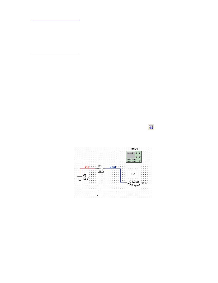
Let’s measure the voltage drop across the potentiometer.
1. First remove the capacitor and replace the AC voltage source with the original
DC voltage source. Next,
Click
the Agilent Multimeter
in the Instruments
Toolbar and drag the multimeter onto your workspace. Error! Reference
source not found.2 shows the result.
Figure 22 A multimeter placed on to workspace
Now,
Double-click
the multimeter to open up the instrument’s front panel.
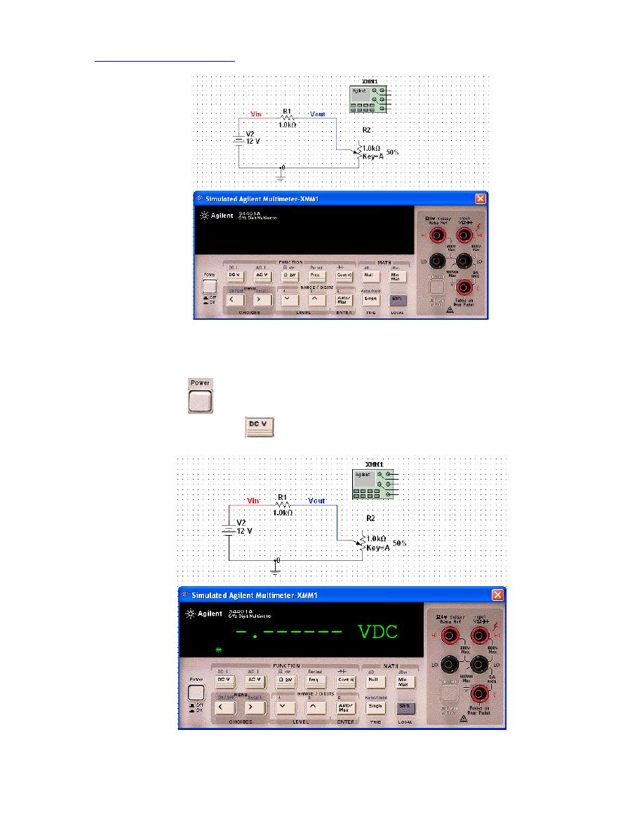
Figure 23 The Agilent 34401A Simulated Multimeter front panel
Notice how the simulated multimeter is the same as the one on your workbench!
Click
the
button to turn on the instrument. You will be measuring DC
voltage, so
Click
the
button on the instrument. Error! Reference source
not found.4 shows what you should get.
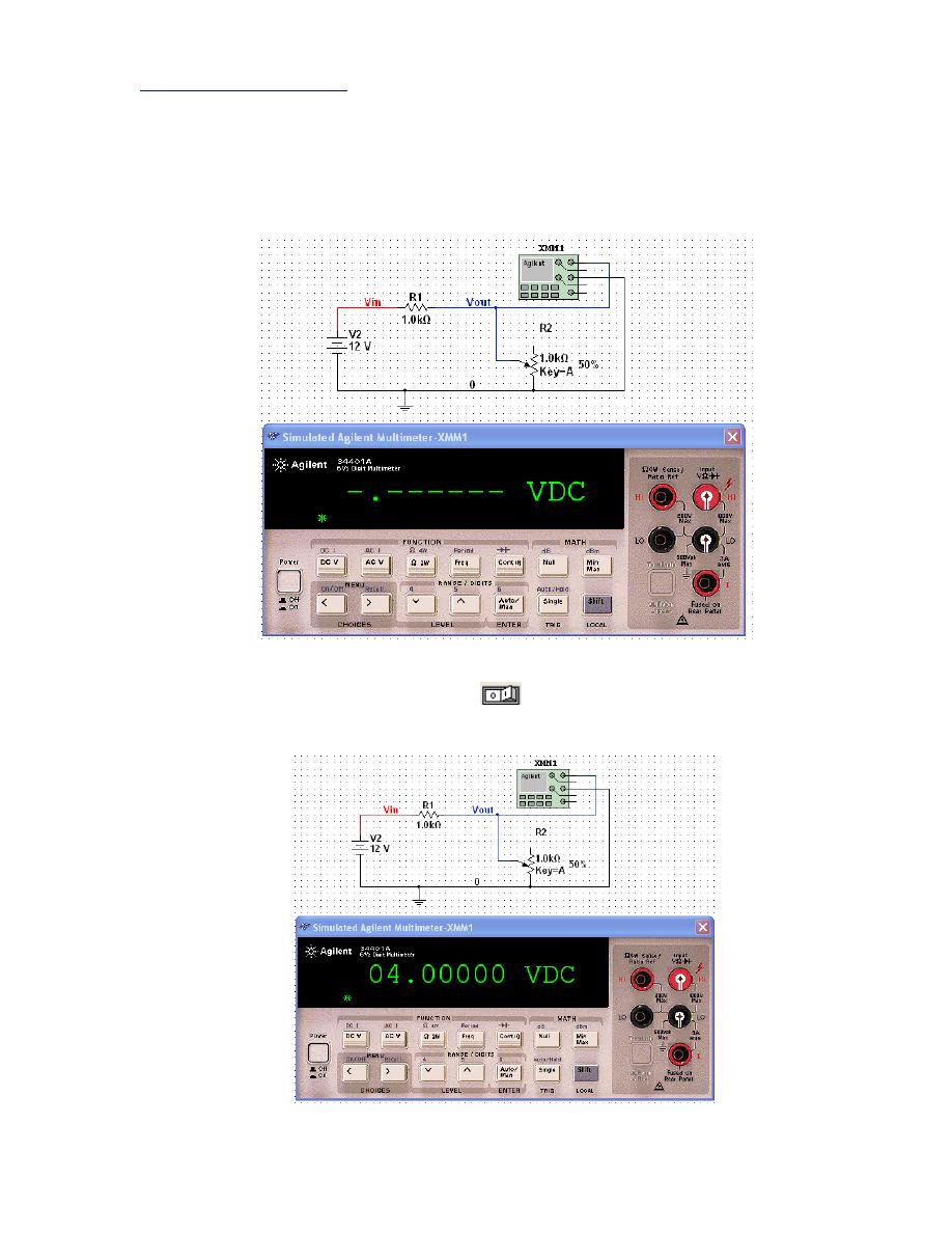
Figure 24 The Multimeter is set to the correct measurement mode
Lastly, draw wires from the multimeter terminals to the circuit as shown in
Error! Reference source not found.5. As you make the connections, MultiSim
highlights the terminals on the frontpanel.
Figure 25 Ready for simulation
2. To simulate the circuit,
Click
the
button in the
Simulation Toolbar
.
Error! Reference source not found.6 shows the result.
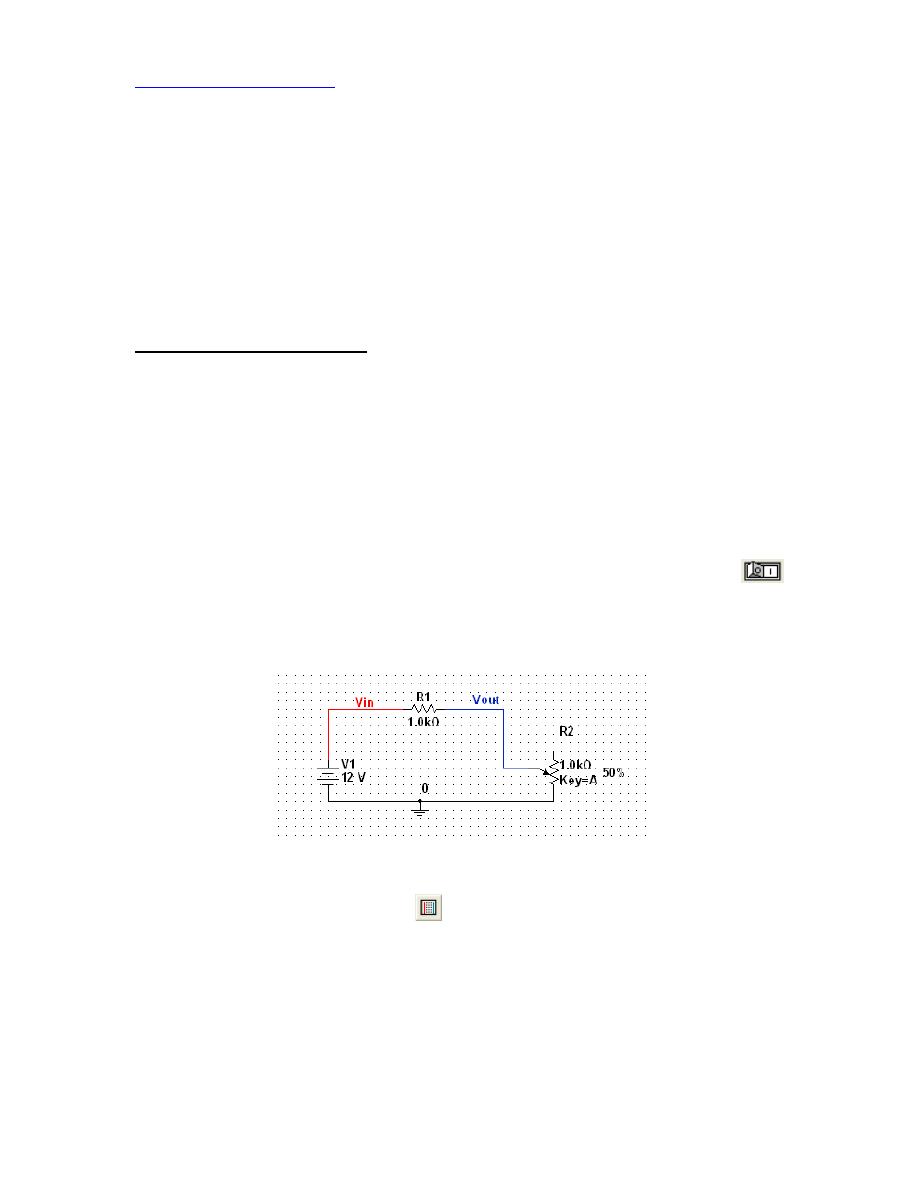
Figure 26 The simulation result
One of the most powerful features of MultiSim is its interactive nature. Change
the resistance of the potentiometer by pressing “A” or Shift+A and note how the
multimeter readings change (you may need to wait a couple of seconds for the
multimeter to register the change). Change the potentiometer resistance all the
way to 1 kΩ (100%). What is the output voltage? Does this agree with your
intuition? Hint: Think about what happens to the voltage divider formula when
R1 = R2.
8. Using the Breadboard Tool
If you have trouble in the laboratory mapping circuit diagrams to the solderless
breadboard, this section is for you. The breadboard tool allows you to see your circuit as
if you had physically constructed it in lab. This tool is invaluable for large circuits (like
your project) because it can help you plan an organized layout of the components before
you actually build your circuit. Similar to using MultiSim's simulated instruments,
though, this process tends to be time consuming. So once you are comfortable with
schematic diagrams, you should probably forgo using the simulated breadboard tool.
We will try the breadboard tool with our simple DC circuit from Section 5. First, delete
the multimeter from your circuit (be sure to turn of the simulation by pressing the
button before you try and delete the multimeter). Although you could wire the multimeter
on the breadboard, it is inconvenient and unnecessary. The circuit to be wired should
look like Error! Reference source not found.7.
Figure 27 The simple DC circuit from the previous section
1.
Click
on the Breadboard icon
in the
Main Toolbar
to open the Breadboard
view. Error! Reference source not found.8 shows the breadboard view.
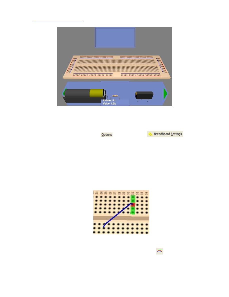
Figure 28 The Breadboard view in MultiSim
The tray at the bottom has all of the circuit elements in your schematic. For us,
that includes a battery, a potentiometer and a resistor. You can change the size of
your breadboard by
clicking
and then selecting
.
You can rotate the breadboard by moving the cursor outside of the breadboard or to the
middle of the breadboard until it changes to a set of double arrows.
Click
and drag the
mouse to rotate the breadboard. If you hold the middle-mouse button, you can drag the
mouse to move or translate across your breadboard. If you move the cursor over any
other area of the breadboard, you get a small wire pointer. Use this tool to place wires on
the breadboard.
Click
one slot on the breadboard and drag a wire to another slot. Error!
Reference source not found.9 shows a wire on the breadboard. MultiSim highlights the
point on the breadboard that you are wiring to, which makes wiring easier when you have
a lot of components on the breadboard.
Figure 29 Breadboard wiring in MultiSim
To change the wire color,
click
the BreadBoard Wire Color
icon in the top
toolbar. It is a good idea to stick to the wire colors you followed when wiring the
schematic.
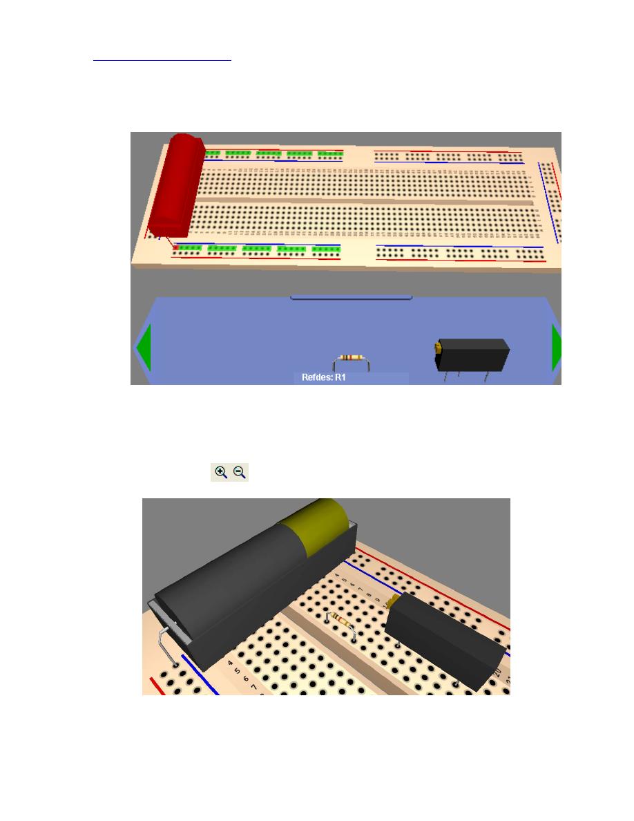
2.
Click
and drag the battery from the bottom tray to the breadboard. Use
Ctrl+R
to
rotate the battery so the position is as shown in 30.
Figure 30 The battery is placed on the breadboard. We are using the outer connectors for the power,
which is the convention followed when using a breadboard.
3. Place the resistor and potentiometer as shown in Error! Reference source not
found.1. Once you place all of the components, the tray disappears. You can use
the Zoom icons
on the top toolbar to get a better look at the components.
Figure 31 Components have been placed on the breadboard.
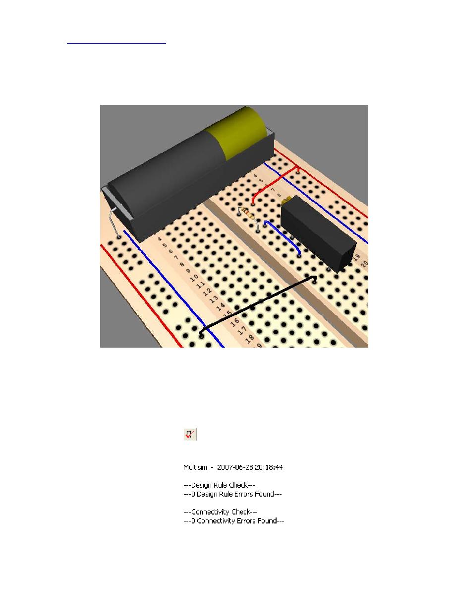
4. Wire the components as shown in Error! Reference source not found.2. Again
it is prudent to follow the color convention you used on the schematic. As you
wire, MultiSim actually highlights the connection end-point. Remember to draw
the wire from the 1 kΩ resistor to the wiper (middle-leg) of the potentiometer.
Figure 32 Wiring complete
5. A powerful feature of the MultiSim breadboard tool is the DRC (Design-Rules-
Check) and Connectivity check. DRC checks if you have wires on the breadboard
that are not on the schematic. Connectivity checks if your components are
actually connected to each other.
Let's run the DRC and Connectivity check.
Click
the Perform DRC and
Connectivity check icon
in the top toolbar. The status window at the bottom
shows the results, which should match Error! Reference source not found.3.
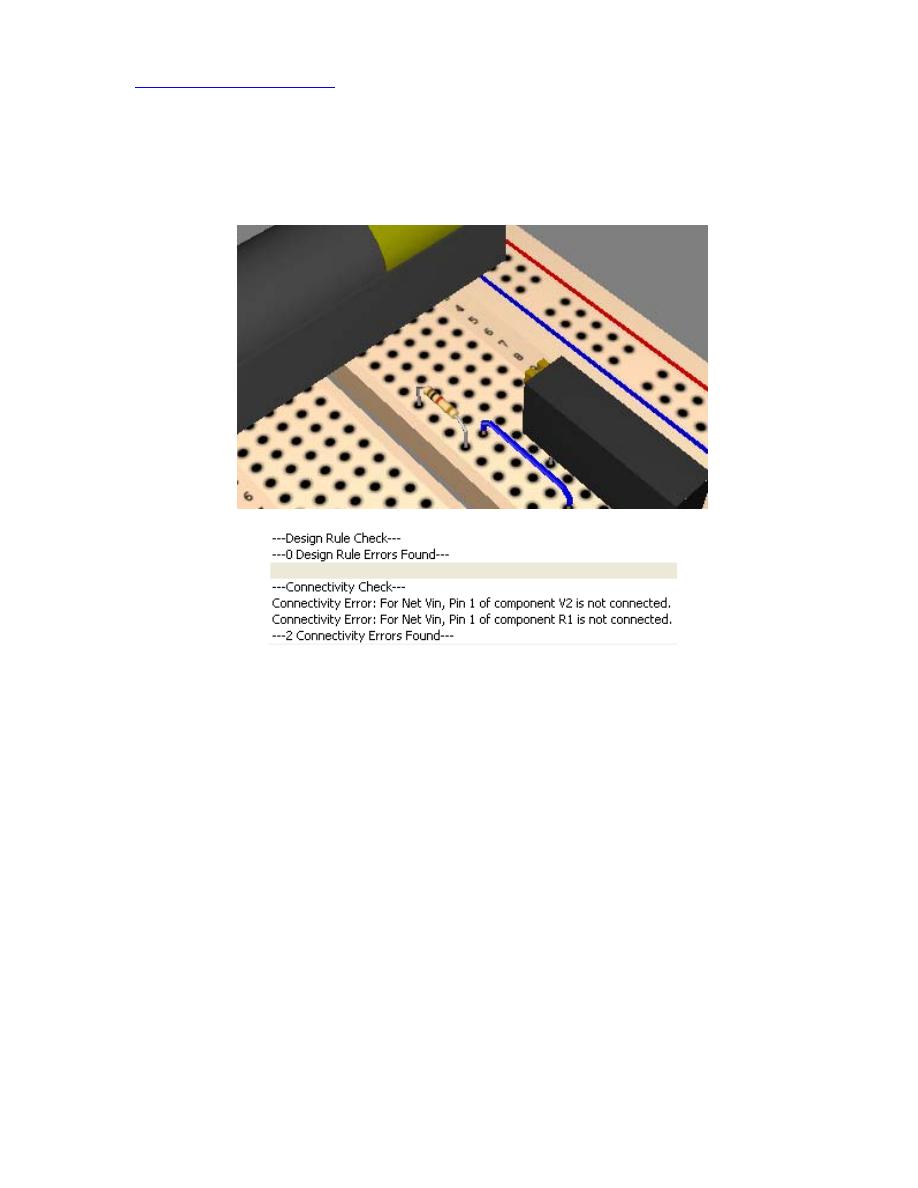
Figure 33 Results from the DRC and Connectivity check
6. Let's introduce a connectivity error. Delete the wire connected to the positive
terminal of the battery (the red wire). The result is shown in Error! Reference
source not found.4.
Figure 34 A Connectivity error has been introduced
If you rerun the DRC and Connectivity check, you should get a whole bunch of
Connectivity errors.
7. Now let's introduce a design error. Rewire the positive terminal of the battery but
short the 1 kΩ resistor by adding a wire in parallel with it. The result is shown in
Error! Reference source not found.5.
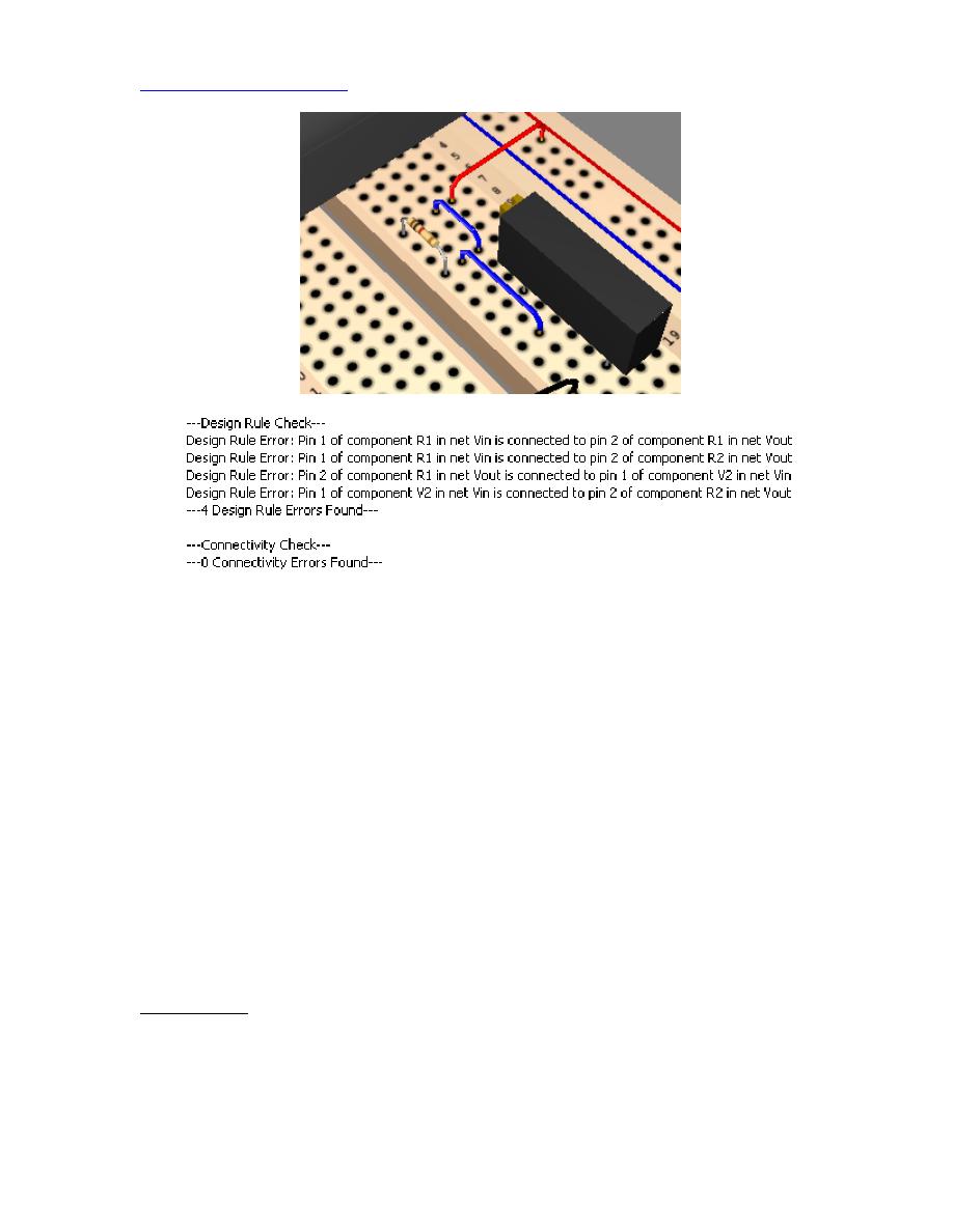
Figure 35 A Design error
If you rerun the DRC and Connectivity check, you will get a bunch of Design
errors. Delete the extra wire to remove the problem.
In this section you saw how you to use the breadboard tool to quickly wire your circuit on
a virtual breadboard. The main purpose of this tool is to give you an idea of the
component layout on the breadboard. For a simple example like this, using the tool is
overkill. But for more complicated circuits like your class project, the breadboard tool
may be invaluable in helping you plan out your component layout.
The Concept of a Ground
Nevertheless, this simple circuit does introduce a very powerful concept. Notice that we
did not place a ground on the breadboard and no error occurred. Hopefully, this rather
subtle point help clarifies the concept of a ground: it is just a symbol on your circuit that
indicates your reference node. A circuit does not need to have an explicit ground
connection to Earth (unless you are dealing with very high voltages and want to provide a
safe return path). Many circuits do not have any explicit ground connection to Earth
8. Conclusion
This document has barely scratched the surface of MultSim, and there are many more
powerful tools that are a part of this version of SPICE. Hopefully this document did give
you a strong start in circuit simulation using MultiSim. The best way to learn is to

experiment, don’t be afraid to try out complicated circuits and MultiSim’s new features.