Simple Stresses
Simple stresses are expressed as the ratio of the applied force divided by the resisting
area or
σ = Force / Area.
It is the expression of force per unit area to structural members that are subjected to
external forces and/or induced forces. Stress is the lead to accurately describe and
predict the elastic deformation of a body.
Simple stress can be classified as normal stress, shear stress, and bearing stress.
Normal stress develops when a force is applied perpendicular to the cross-sectional
area of the material. If the force is going to pull the material, the stress is said to be
tensile stress and compressive stress develops when the material is being
compressed by two opposing forces. Shear stress is developed if the applied force is
parallel to the resisting area. Example is the bolt that holds the tension rod in its
anchor. Another condition of shearing is when we twist a bar along its longitudinal axis.
This type of shearing is called torsion and covered in Chapter 3. Another type of simple
stress is the bearing stress, it is the contact pressure between two bodies.
Suspension bridges are good example of structures that carry these stresses. The
weight of the vehicle is carried by the bridge deck and passes the force to the stringers
(vertical cables), which in turn, supported by the main suspension cables. The
suspension cables then transferred the force into bridge towers.
Normal Stress
Stress
Stress is the expression of force applied to a unit area of surface. It is measured in psi
(English unit) or in MPa (SI unit). Another unit of stress which is not commonly used is
the dynes (cgs unit). Stress is the ratio of force over area.
stress = force / area
Simple Stresses
There are three types of simple stress namely; normal stress, shearing stress, and
bearing stress.
Normal Stress
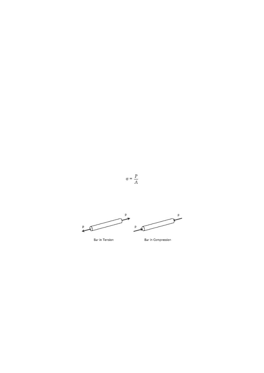
The resisting area is perpendicular to the applied force, thus normal. There are two
types of normal stresses; tensile stress and compressive stress. Tensile stress applied
to bar tends the bar to elongate while compressive stress tend to shorten the bar.
where P is the applied normal load in Newton and A is the area in mm
2
. The maximum
stress in tension or compression occurs over a section normal to the load.
SOLVED PROBLEMS IN NORMAL STRESS
Problem 104
A hollow steel tube with an inside diameter of 100
mm must carry a tensile load of 400 kN. Determine
the outside diameter of the tube if the stress is limited
to 120 MN/m
2
.
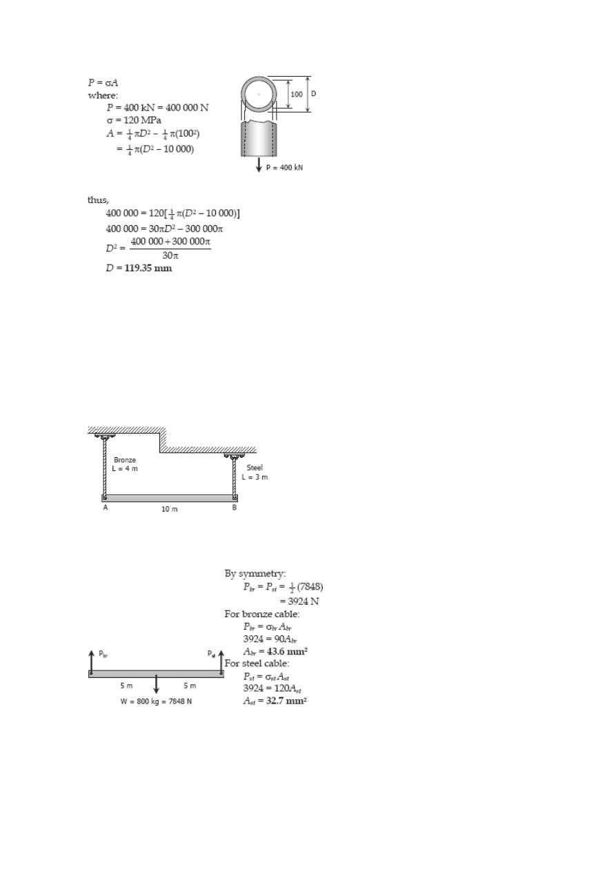
Solution 104
Problem 105
A homogeneous 800 kg bar AB is supported at either
end by a cable as shown in Fig. P-105. Calculate the
smallest area of each cable if the stress is not to exceed
90 MPa in bronze and 120 MPa in steel.
Figure P-105
Solution 105
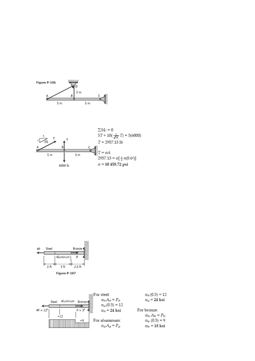
Problem 106
The homogeneous bar shown in Fig. P-106 is
supported by a smooth pin at C and a cable that runs
from A to B around the smooth peg at D. Find the
stress in the cable if its diameter is 0.6 inch and the
bar weighs 6000 lb.
Solution 106
Problem 107
A rod is composed of an aluminum section rigidly
attached between steel and bronze sections, as shown
in Fig. P-107. Axial loads are applied at the positions
indicated. If P = 3000 lb and the cross sectional area
of the rod is 0.5 in
2
, determine the stress in each
section.
Solution 107
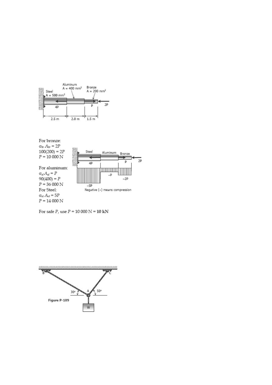
Problem 108
An aluminum rod is rigidly attached between a steel rod and a bronze rod as shown in
Fig. P-108. Axial loads are applied at the positions indicated. Find the maximum value of
P that will not exceed a stress in steel of 140 MPa, in aluminum of 90 MPa, or in bronze
of 100 MPa.
Figure P-108
Solution 108
Problem 109
Determine the largest weight W that can be supported by two wires shown in Fig. P-
109. The stress in either wire is not to exceed 30 ksi. The cross-sectional areas of wires
AB and AC are 0.4 in
2
and 0.5 in
2
, respectively.
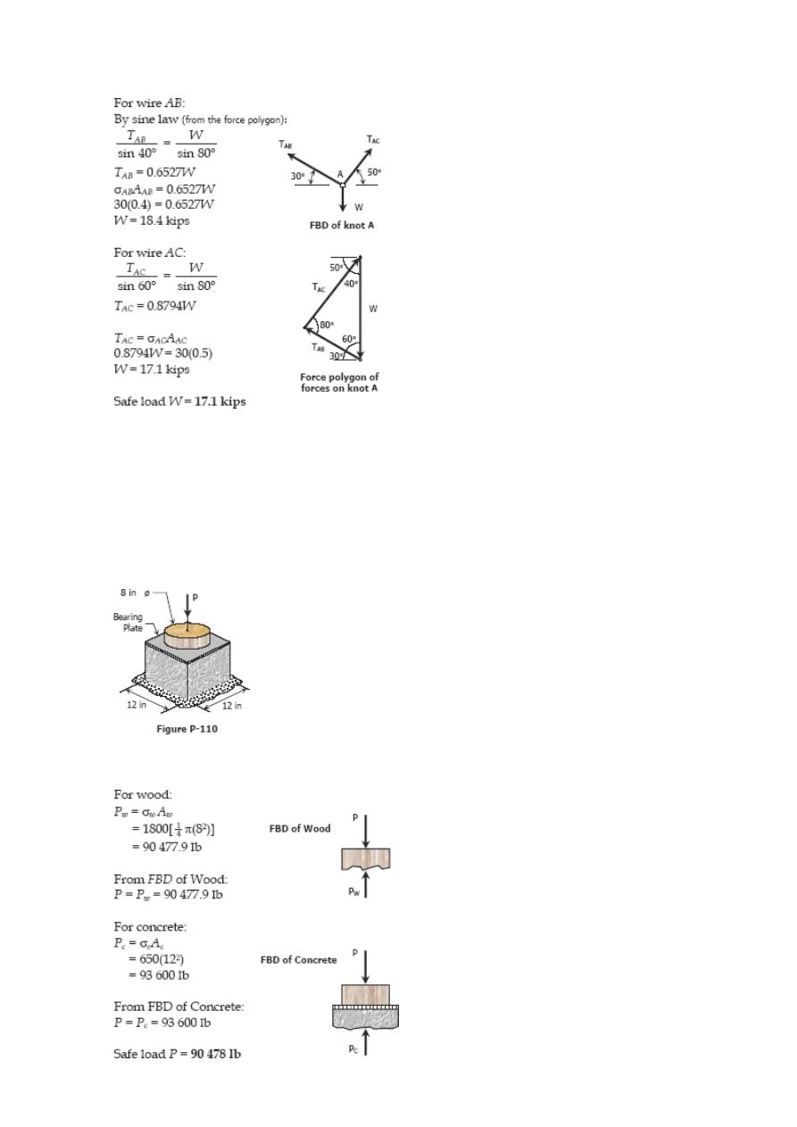
Solution 109
Problem 110
A 12-inches square steel bearing plate lies between an 8-inches diameter
wooden post and a concrete footing as shown in Fig. P-110. Determine
the maximum value of the load P if the stress in wood is limited to 1800
psi and that in concrete to 650 psi.
Solution 110
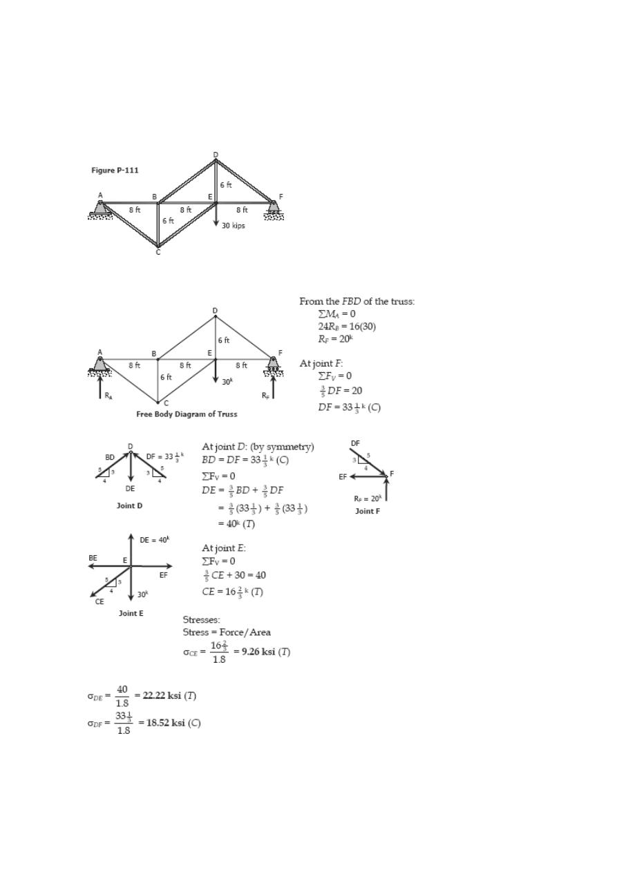
Problem 111
For the truss shown in Fig. P-111, calculate the stresses in members CE, DE, and DF.
The crosssectional area of each member is 1.8 in
2
. Indicate tension (T) or compression
(C).
Solution 111
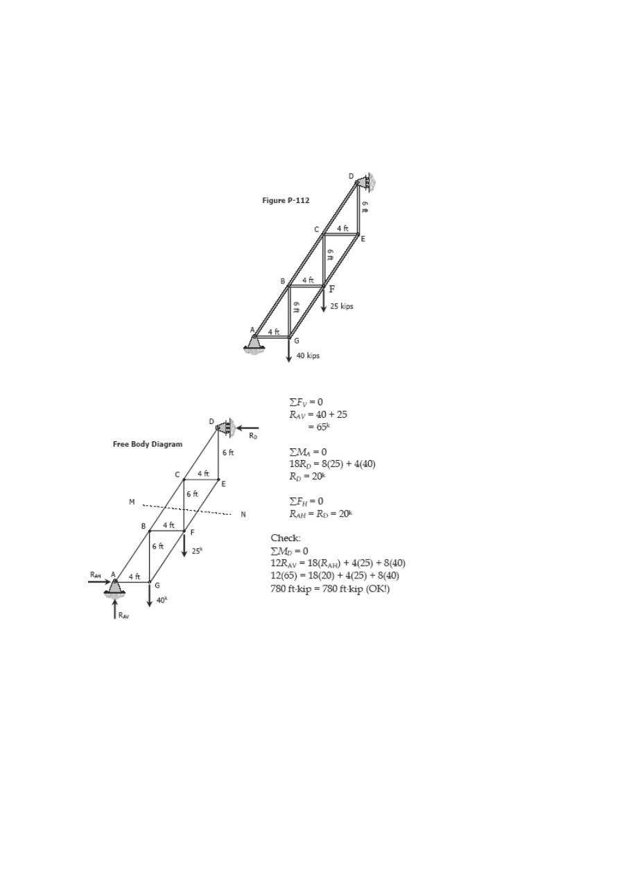
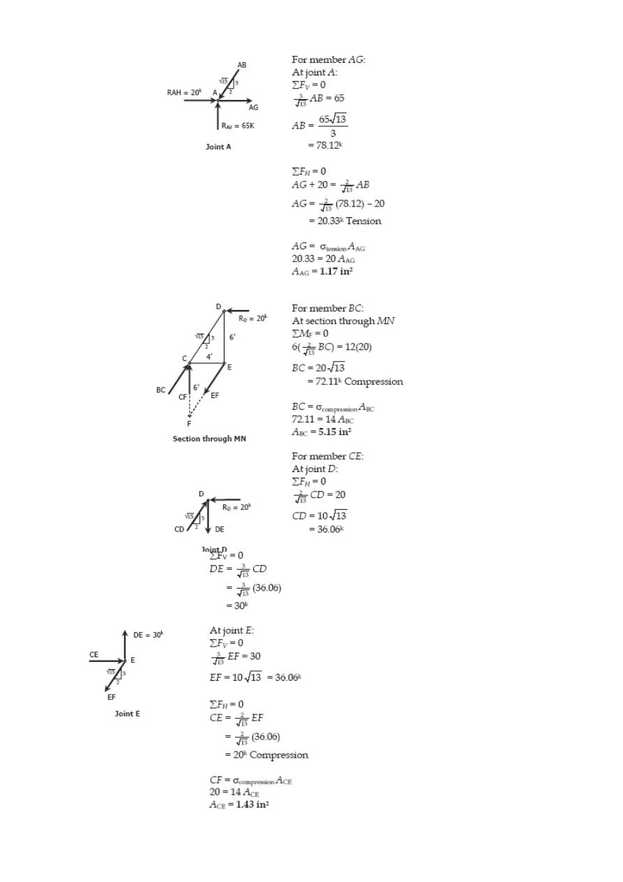
Problem 112
Determine the crosssectional areas of members AG, BC, and CE for the truss shown in
Fig. P-112 above. The stresses are not to exceed 20 ksi in tension and 14 ksi in
compression. A reduced stress in compression is specified to reduce the danger of
buckling.
Solution 112
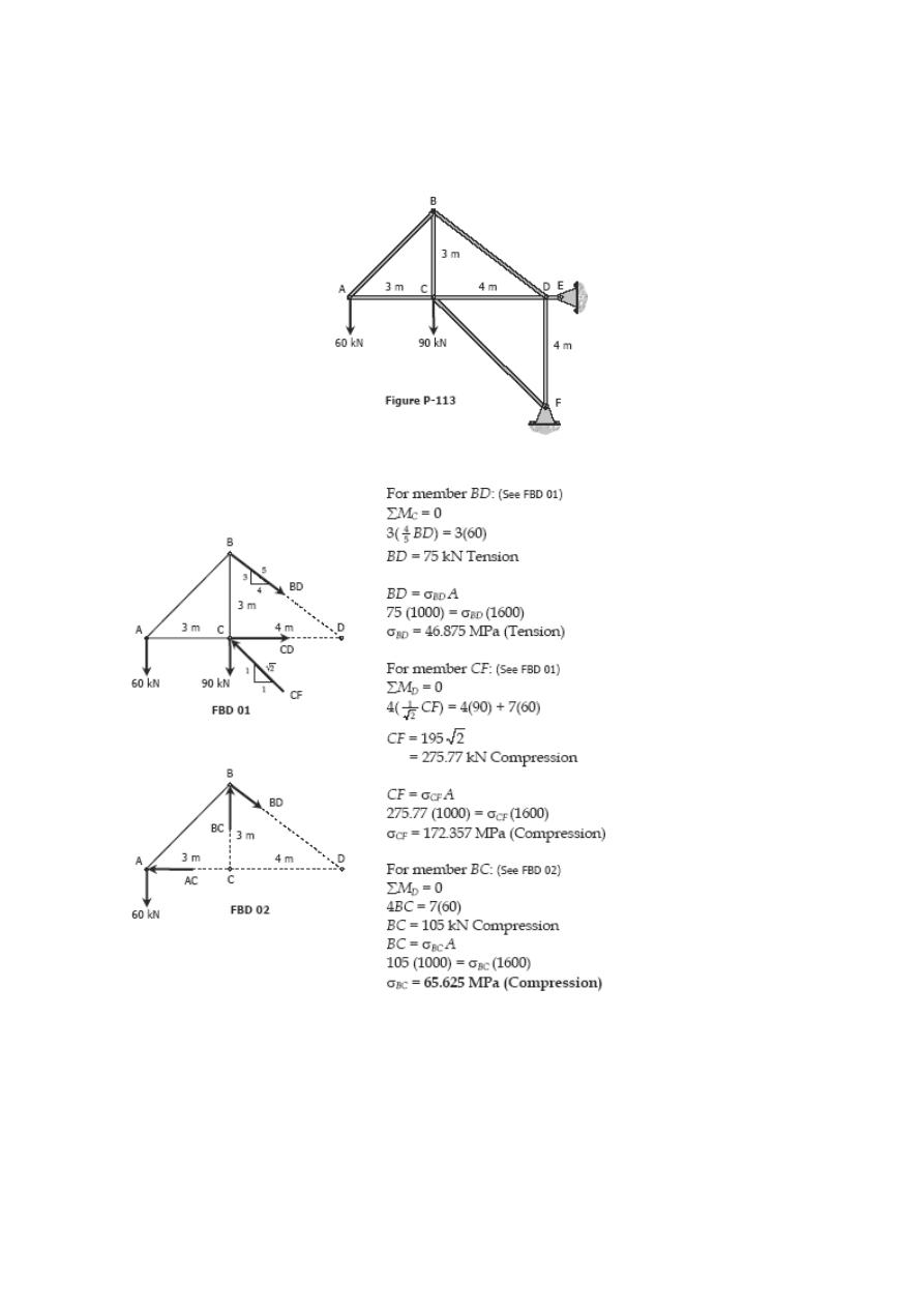
Problem 113
Find the stresses in members BC, BD, and CF for the truss shown in Fig. P-113. Indicate
the tension or compression. The cross sectional area of each member is 1600 mm
2
.
Solution 113
Problem 114
The homogeneous bar ABCD shown in Fig. P-114 is supported by a cable that runs from
A to B around the smooth peg at E, a vertical cable at C, and a smooth inclined surface
at D. Determine the mass of the heaviest bar that can be supported if the stress in each
cable is limited to 100 MPa. The area of the cable AB is 250 mm
2
and that of the cable
at C is 300 mm
2
.
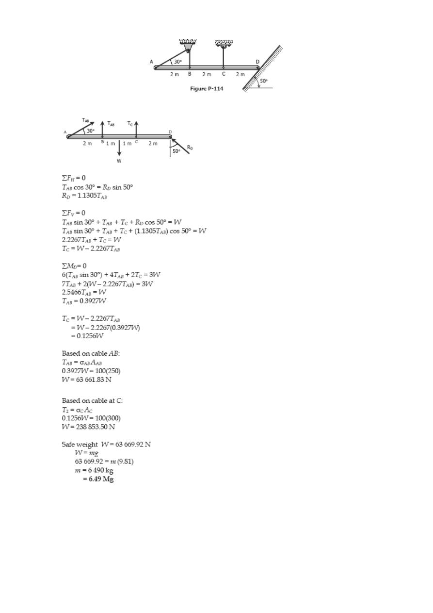
Solution 114
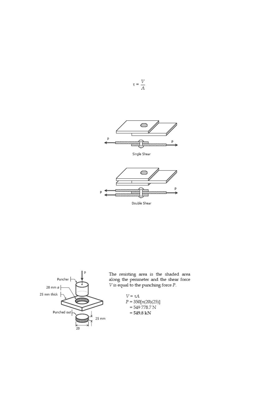
Shearing Stress
Forces parallel to the area resisting the force cause shearing stress. It differs to tensile
and compressive stresses, which are caused by forces perpendicular to the area on
which they act. Shearing stress is also known as tangential stress.
where V is the resultant shearing force which passes which passes through the centroid
of the area A being sheared.
SOLVED PROBLEMS IN SHEARING STRESS
Problem 115
What force is required to punch a 20-mm-diameter hole in a plate that is 25 mm thick?
The shear strength is 350 MN/m
2
.
Solution 115

Problem 116
As in Fig. 1-11c, a hole is to be punched out of a plate having a shearing strength of 40
ksi. The compressive stress in the punch is limited to 50 ksi. (a) Compute the maximum
thickness of plate in which a hole 2.5 inches in diameter can be punched. (b) If the
plate is 0.25 inch thick, determine the diameter of the smallest hole that can be
punched.
Solution 116
Problem 117
Find the smallest diameter bolt that can be used in the clevis shown in Fig. 1-11b if P =
400 kN. The shearing strength of the bolt is 300 MPa.
Solution 117
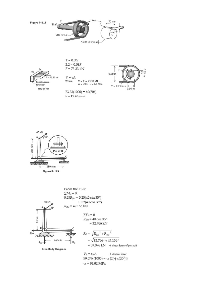
Problem 118
A 200-mm-diameter pulley is prevented from rotating relative to 60-mm-diameter shaft
by a 70-mm-long key, as shown in Fig. P-118. If a torque T = 2.2 kN·m is applied to the
shaft, determine the width b if the
allowable shearing stress in the key is 60 MPa.
Solution 118
Problem 119
Compute the shearing stress in the pin at B for the member supported as
shown in Fig. P-119. The pin diameter is 20 mm.
Solution 119
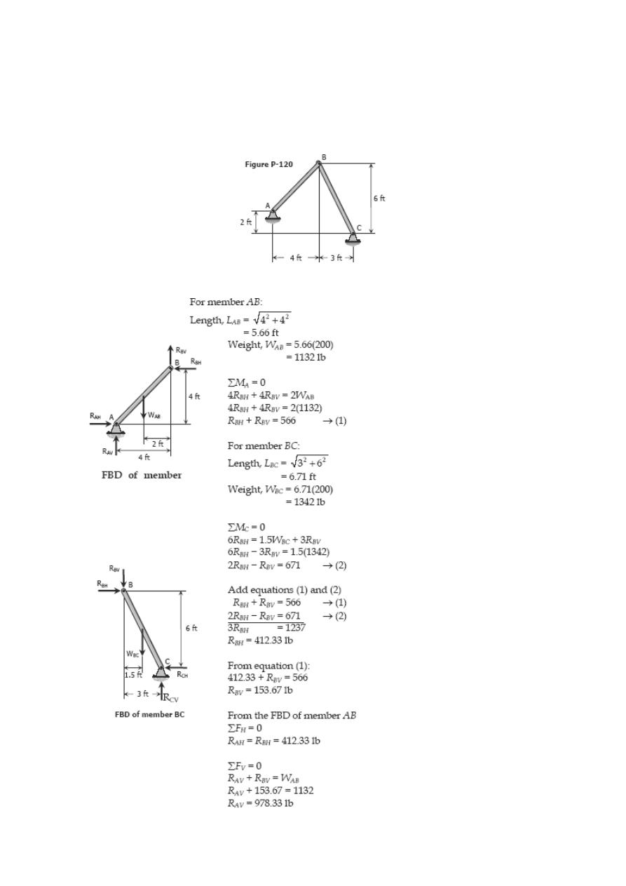
Problem 120
The members of the structure in Fig. P-120 weigh 200 lb/ft. Determine the smallest
diameter pin that can be used at A if the shearing stress is limited to 5000 psi. Assume
single shear.
Solution 120
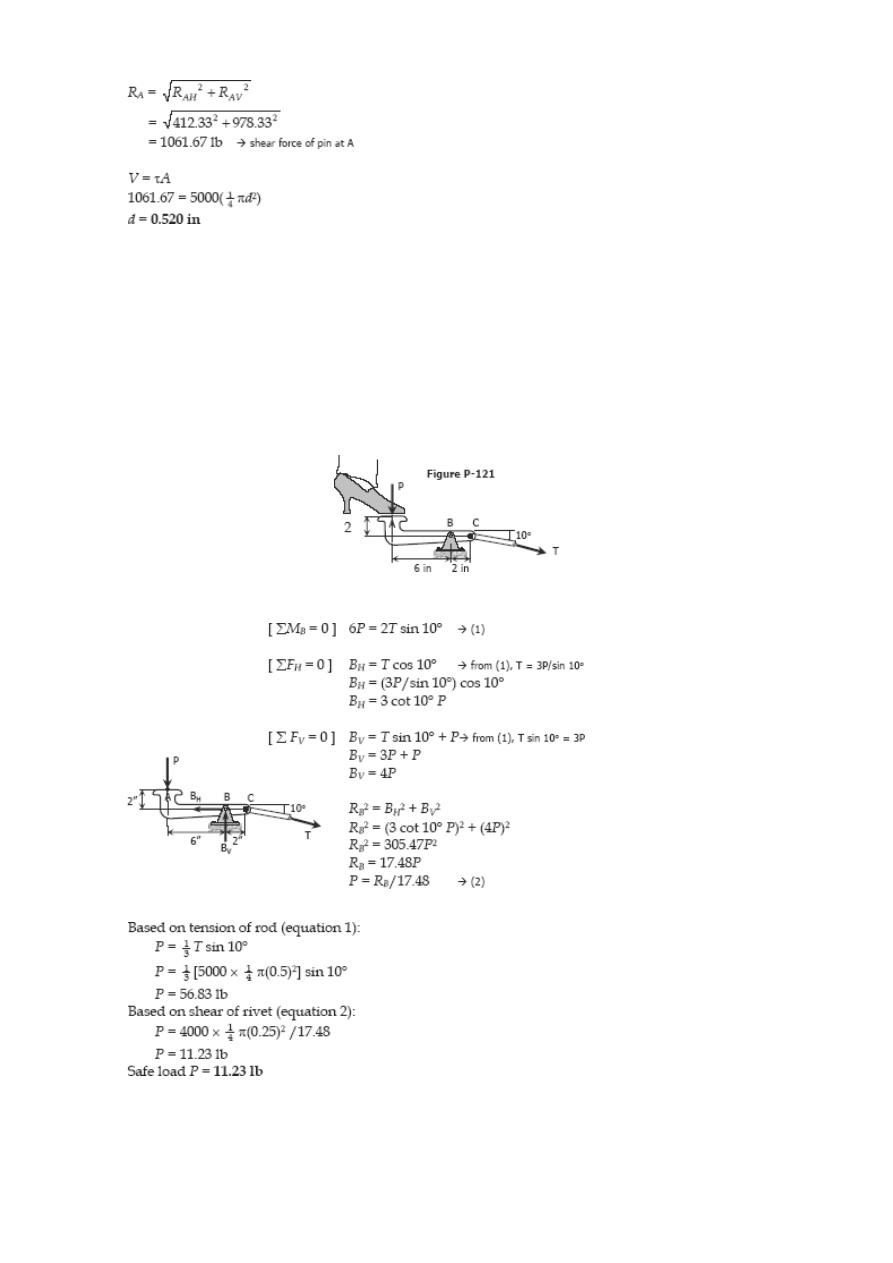
Problem 121
Referring to Fig. P-121, compute the maximum force P that can be applied by the
machine operator, if the shearing stress in the pin at B and the axial stress in the
control rod at C are limited to 4000 psi and 5000 psi, respectively. The diameters are
0.25 inch for the pin, and 0.5 inch for the control rod. Assume single shear for the pin
at B.
Solution 121
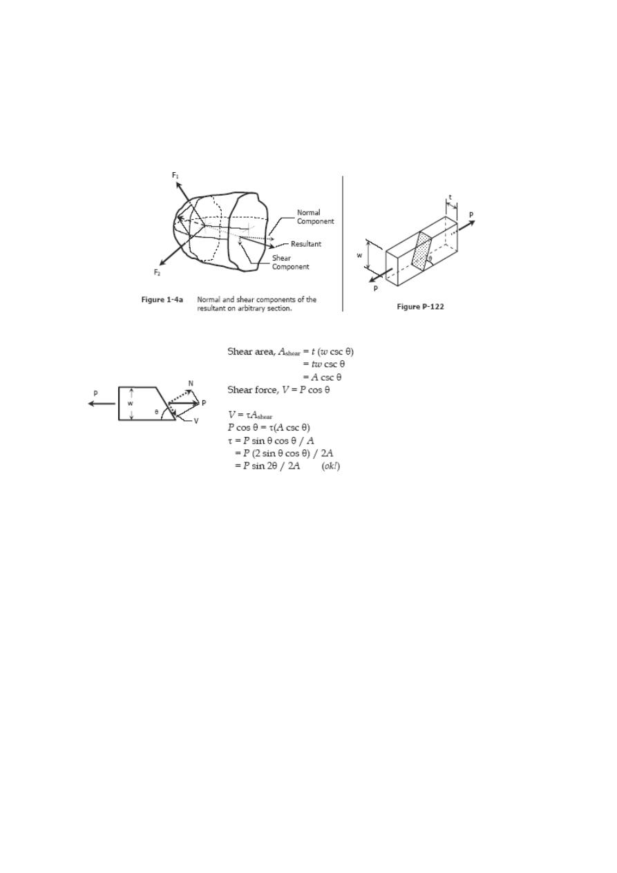
Problem 122
Two blocks of wood, width w and thickness t, are glued together along the joint inclined
at the angle θ as shown in Fig. P-122. Using the free-body diagram concept in Fig. 1-4a,
show that the shearing stress on the glued joint is τ = P sin 2θ/2A, where A is the cross-
sectional area.
Solution 122
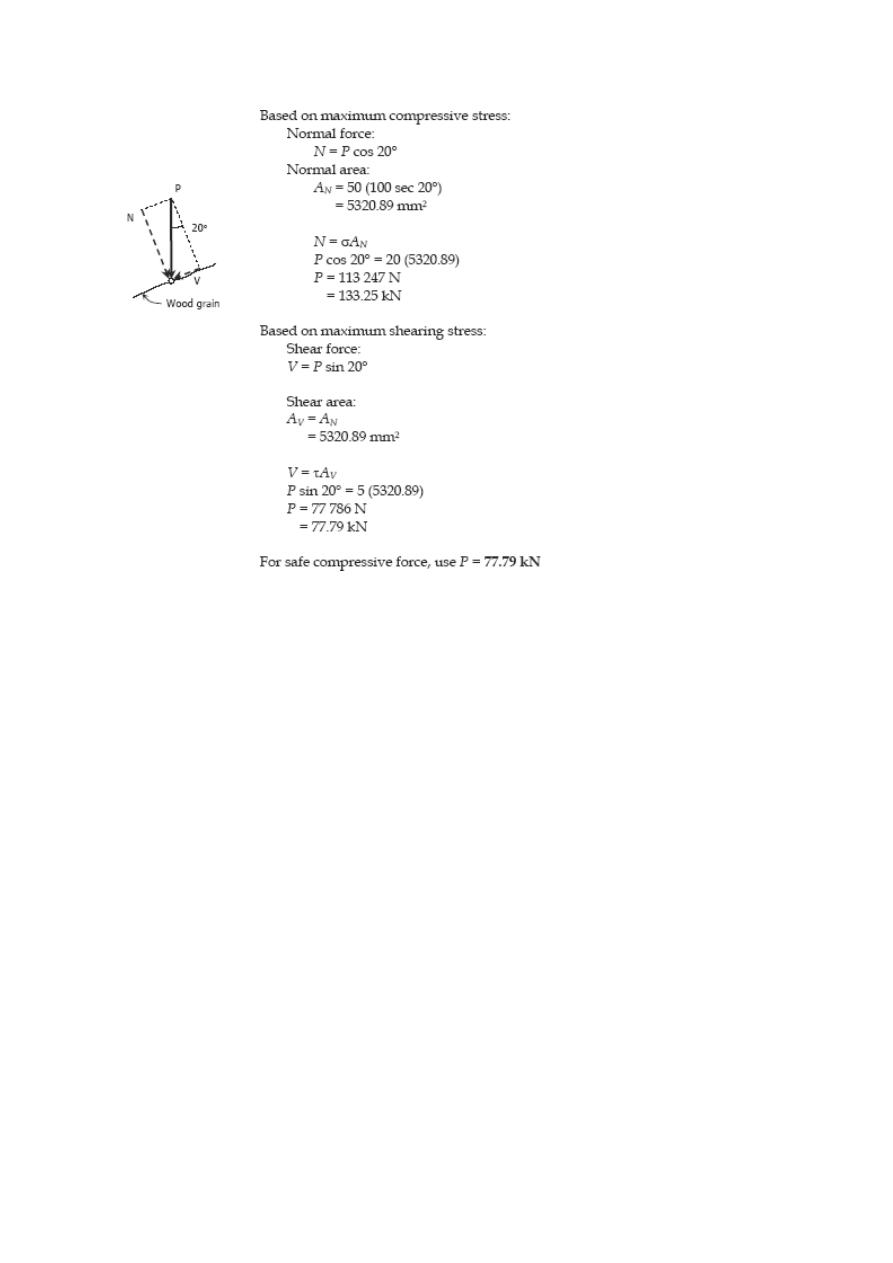
Problem 123
A rectangular piece of wood, 50 mm by 100 mm in cross section, is used as a
compression block shown in Fig. P-123. Determine the axial force P that can be safely
applied to the block if the compressive stress in wood is limited to 20 MN/m
2
and the
shearing stress parallel to the grain is limited to 5 MN/m
2
. The grain makes an angle of
20° with the horizontal, as shown. (Hint: Use the results in Problem 122.)
Solution 123
Bearing Stress
Bearing stress is the contact pressure between the separate bodies. It differs from
compressive stress, as it is an internal stress caused by compressive forces.
SOLVED PROBLEMS IN BEARING STRESS
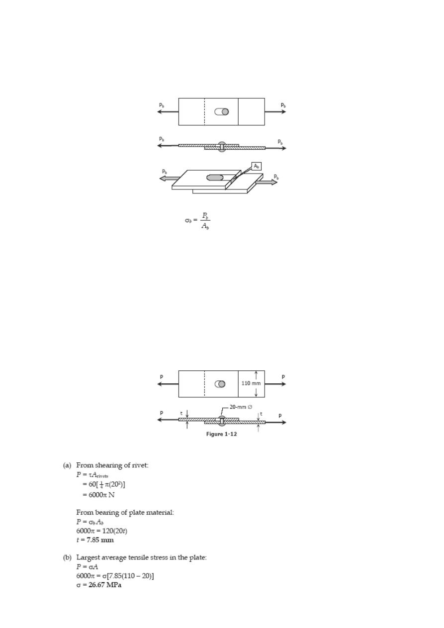
Problem 125
In Fig. 1-12, assume that a 20-mm-diameter rivet joins the plates that are each 110
mm wide. The allowable stresses are 120 MPa for bearing in the plate material and 60
MPa for shearing of rivet. Determine (a) the minimum thickness of each plate; and (b)
the largest average tensile stress in the plates.
Solution 125
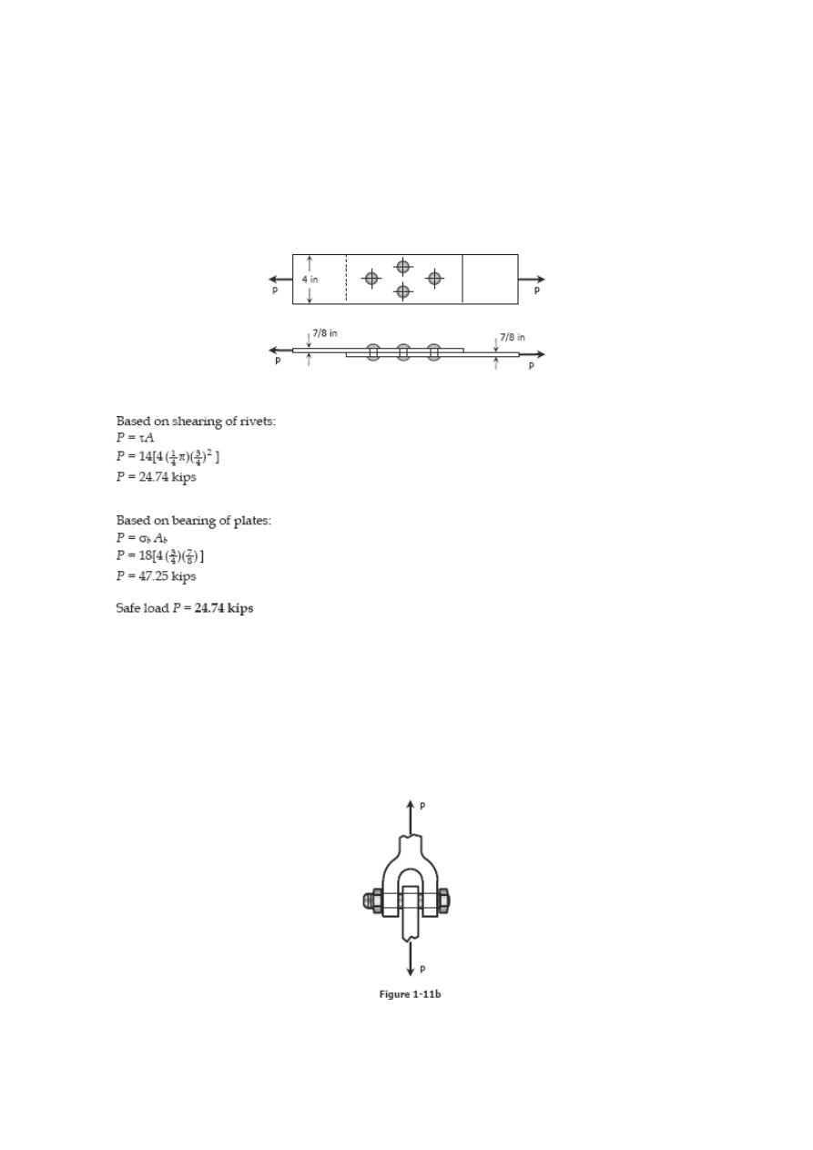
Problem 126
The lap joint shown in Fig. P-126 is fastened by four ¾-in.-diameter rivets. Calculate
the maximum safe load P that can be applied if the shearing stress in the rivets is
limited to 14 ksi and the bearing stress in the plates is limited to 18 ksi. Assume the
applied load is uniformly distributed among the four rivets.
Solution 126
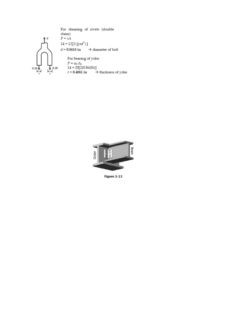
Problem 127
In the clevis shown in Fig. 1-11b, find the minimum bolt diameter and the minimum
thickness of each yoke that will support a load P = 14 kips without exceeding a shearing
stress of 12 ksi and a bearing stress of 20 ksi.
Solution 127
Problem 128
A W18 × 86 beam is riveted to a W24 × 117 girder by a connection similar to that in
Fig. 1-13. The diameter of the rivets is 7/8 in., and the angles are each 4 × 31/2 × 3/8
in. For each rivet, assume that the allowable stresses are τ = 15 ksi and σ
b
= 32 ksi.
Find the allowable
load on the connection.
Solution 128
Note: Textbook is Strength of Materials 4th edition by Pytel and Singer
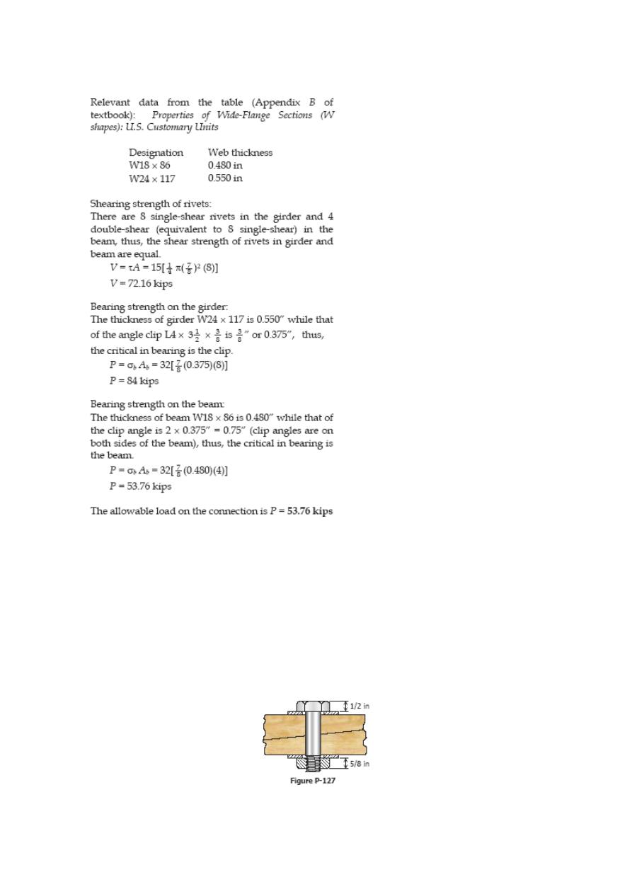
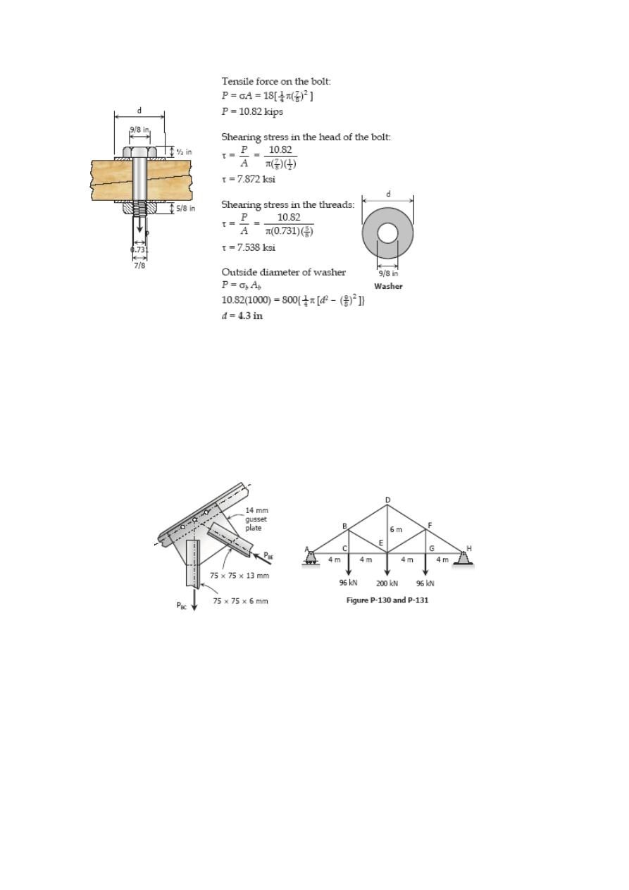
Problem 129
A 7/8-in.-diameter bolt, having a diameter at the root of the threads of 0.731 in., is
used to fasten two timbers together as shown in Fig. P-129. The nut is tightened to
cause a tensile stress of 18 ksi in the bolt. Compute the shearing stress in the head of
the bolt and in the threads. Also, determine the outside diameter of the washers if their
inside diameter is 9/8 in. and the bearing stress is limited to 800 psi.
Solution 129
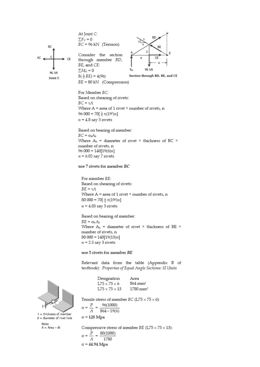
Problem 130
Figure P-130 shows a roof truss and the detail of the riveted connection at joint B. Using
allowable stresses of τ = 70 MPa and σ
b
= 140 MPa, how many 19-mm diameter rivets
are required to fasten member BC to the gusset plate? Member BE? What is the largest
average tensile or compressive stress in BC and BE?
Solution 130
Problem 131
Repeat Problem 130 if the rivet diameter is 22 mm and all other data remain
unchanged.
Solution 131
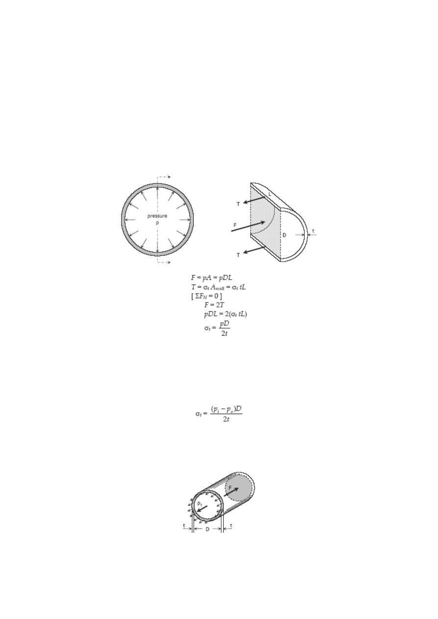
Thin-Walled Pressure Vessels
A tank or pipe carrying a fluid or gas under a pressure is subjected to tensile forces,
which resist bursting, developed across longitudinal and transverse sections.
TANGENTIAL STRESS
(Circumferential Stress)
Consider the tank shown being subjected to an internal pressure p. The length of the
tank is L and the wall thickness is t. Isolating the right half of the tank:
If there exist an external pressure p
o
and an internal pressure p
i
, the formula may be
expressed as:
LONGITUDINAL STRESS, σ
L
Consider the free body diagram in the transverse section of the tank:
The total force acting at the rear of the tank F must equal to the total longitudinal stress
on the wall P
T
= σ
L
A
wall
. Since t is so small compared to D, the area of the wall is close
to πDt
If there exist an external pressure p
o
and an internal pressure p
i
, the formula may be
expressed as:
It can be observed that the tangential stress is twice that of the longitudinal stress.
σ
t
= 2 σ
L
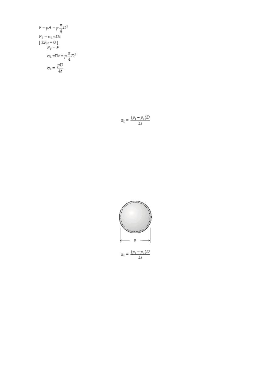
SPHERICAL SHELL
If a spherical tank of diameter D and thickness t contains gas under
a pressure of p, the stress at the wall can be expressed as:
SOLVED PROBLEMS IN THIN WALLED PREASSURE VESSELS
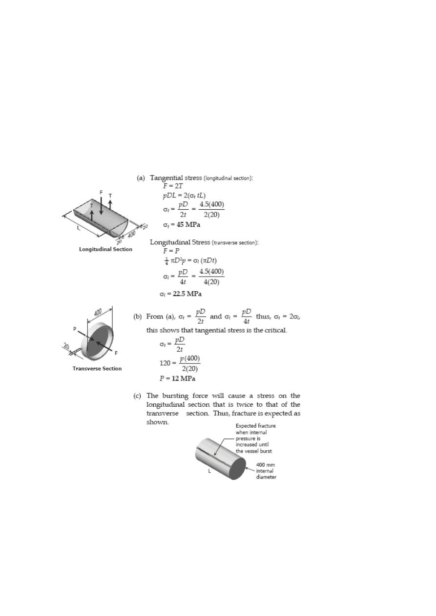
Problem 133
A cylindrical steel pressure vessel 400 mm in diameter with a wall thickness of 20 mm,
is subjected to an internal pressure of 4.5 MN/m
2
. (a) Calculate the tangential and
longitudinal stresses in the steel. (b) To what value may the internal pressure be
increased if the stress in the steel is limited to 120 MN/m
2
? (c) If the internal pressure
were increased until the vessel burst, sketch the type of fracture that would occur.
Solution 133
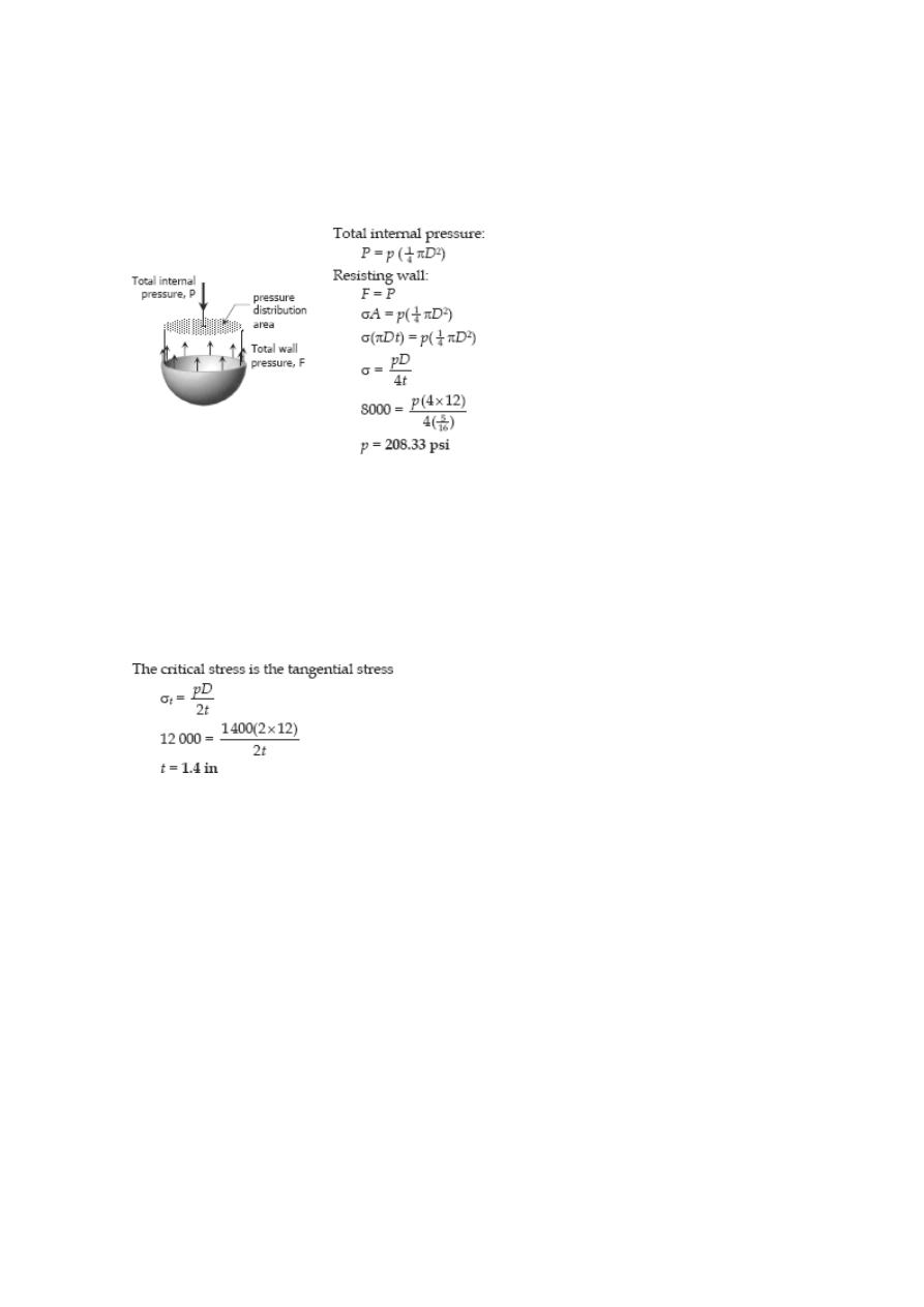
Problem 134
The wall thickness of a 4-ft-diameter spherical tank is 5/16 in. Calculate the allowable
internal pressure if the stress is limited to 8000 psi.
Solution 134
Problem 135
Calculate the minimum wall thickness for a cylindrical vessel that is to carry a gas at a
pressure of 1400 psi. The diameter of the vessel is 2 ft, and the stress is limited to 12
ksi.
Solution 135
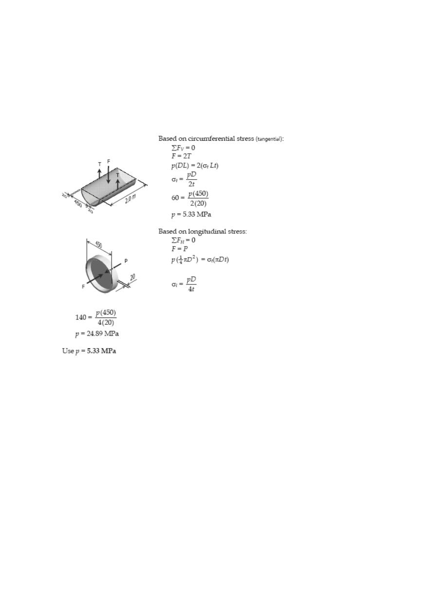
Problem 136
A cylindrical pressure vessel is fabricated from steel plating that has a thickness of 20
mm. The diameter of the pressure vessel is 450 mm and its length is 2.0 m. Determine
the maximum internal pressure that can be applied if the longitudinal stress is limited to
140 MPa, and the circumferential stress is limited to 60 MPa.
Solution 136
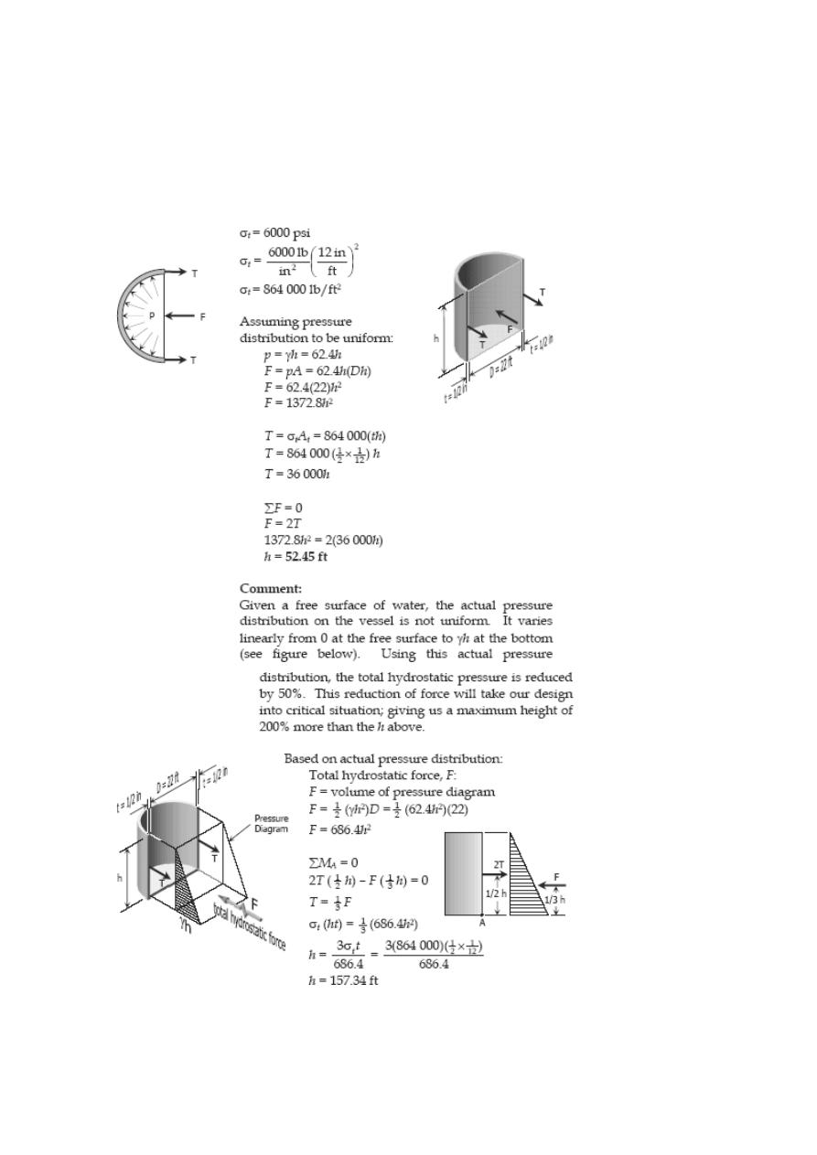
Problem 137
A water tank, 22 ft in diameter, is made from steel plates that are ½ in. thick. Find the
maximum height to which the tank may be filled if the circumferential stress is limited
to 6000 psi. The specific weight of water is 62.4 lb/ft
3
.
Solution 137
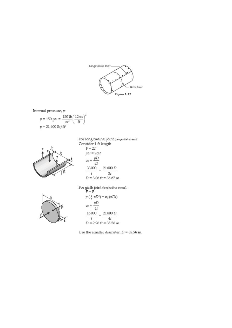
Problem 138
The strength of longitudinal joint in Fig. 1-17 is 33 kips/ft, whereas for the girth is 16
kips/ft. Calculate the maximum diameter of the cylinder tank if the internal pressure is
150 psi.
Solution 138
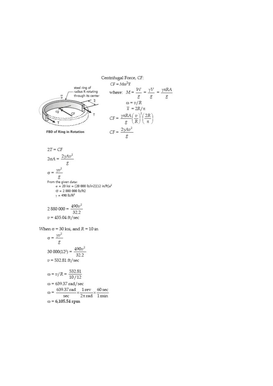
Problem 139
Find the limiting peripheral velocity of a rotating steel ring if the allowable stress is 20
ksi and steel weighs 490 lb/ft
3
. At what revolutions per minute (rpm) will the stress
reach 30 ksi if the mean radius is 10 in.?
Solution 139
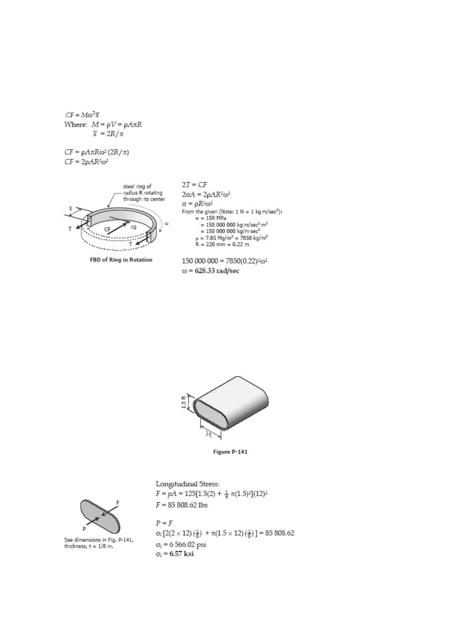
Problem 140
At what angular velocity will the stress of the rotating steel ring equal 150 MPa if its
mean radius is 220 mm? The density of steel 7.85 Mg/m
3
.
Solution 140
Problem 141
The tank shown in Fig. P-141 is fabricated from 1/8-in steel plate. Calculate the
maximum longitudinal and circumferential stress caused by an internal pressure of 125
psi.
Solution 141
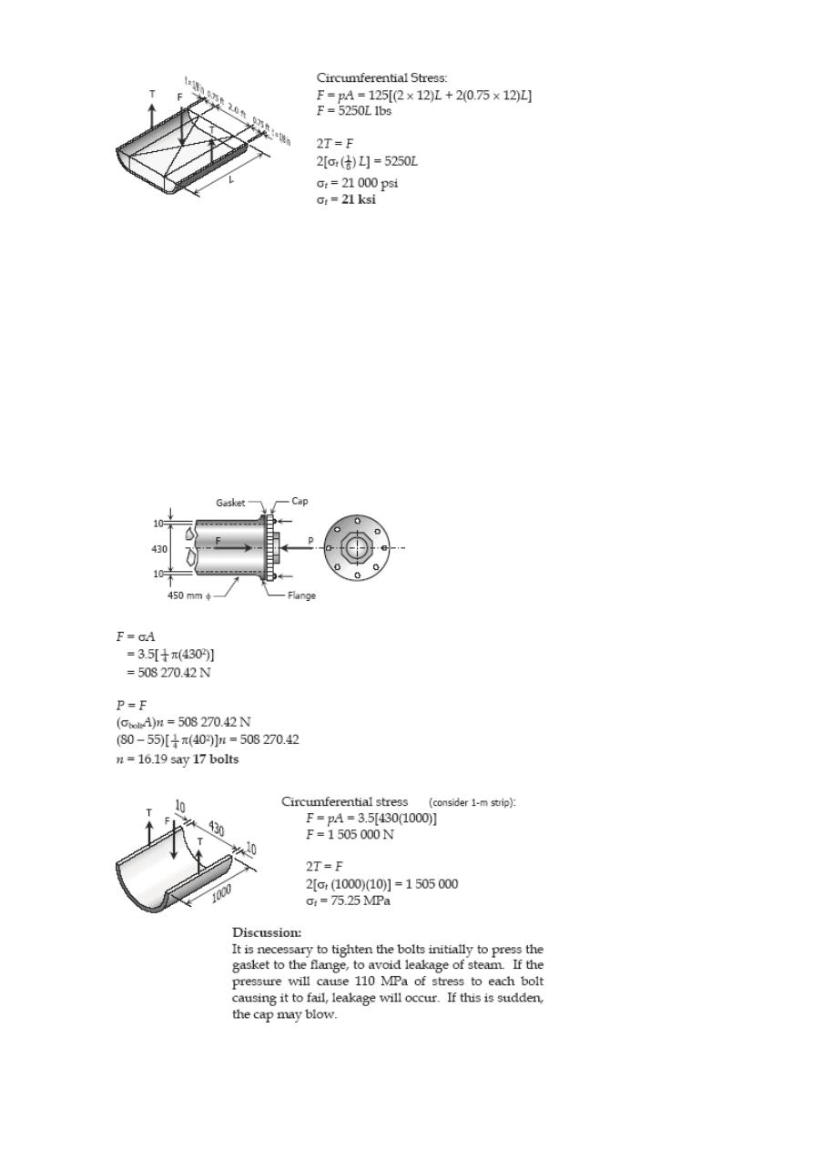
Problem 142
A pipe carrying steam at 3.5 MPa has an outside diameter of 450 mm and a wall
thickness of 10 mm. A gasket is inserted between the flange at one end of the pipe and
a flat plate used to cap the end. How many 40-mm-diameter bolts must be used to hold
the cap on if the allowable stress in the bolts is 80 MPa, of which 55 MPa is the initial
stress? What circumferential stress is developed in the pipe? Why is it necessary to
tighten the bolt initially, and what will happen if the steam pressure should cause the
stress in the bolts to be twice the value of the initial stress?
Solution 142
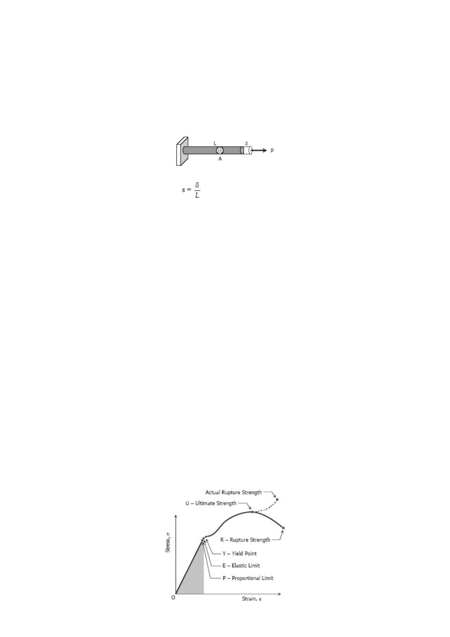
Strain
Simple Strain
Also known as unit deformation, strain is the ratio of the change in length caused by the
applied force, to the original length.
where δ is the deformation and L is the original length, thus ε is dimensionless.
Stress-Strain Diagram
Suppose that a metal specimen be placed in tension-compression testing machine. As
the axial load is gradually increased in increments, the total elongation over the gage
length is measured at each increment of the load and this is continued until failure of
the specimen takes place. Knowing the original cross-sectional area and length of the
specimen, the normal stress σ and the strain ε can be obtained. The graph of these
quantities with the stress σ along the y-axis and the strain ε along the x-axis is called
the stress-strain diagram. The stress-strain diagram differs in form for various
materials. The diagram shown below is that for a medium carbon structural steel.
Metallic engineering materials are classified as either ductile or brittle materials. A
ductile material is one having relatively large tensile strains up to the point of rupture
like structural steel and aluminum, whereas brittle materials has a relatively small strain
up to the point of rupture like cast iron and concrete. An arbitrary strain of 0.05
mm/mm is frequently taken as the dividing line between these two classes.
PROPORTIONAL LIMIT (HOOKE'S LAW)
From the origin O to the point called proportional limit, the stress-strain
curve is a straight line. This linear relation between elongation and the
axial force causing was first noticed by Sir Robert Hooke in 1678 and is
called Hooke's Law that within the proportional limit, the stress is directly
proportional to strain or
The constant of proportionality k is called the Modulus of Elasticity E or Young's Modulus
and is equal to the slope of the stress-strain diagram from O to P. Then
ELASTIC LIMIT
The elastic limit is the limit beyond which the material will no longer go back to its
original shape when the load is removed, or it is the maximum stress that may e
developed such that there is no permanent or residual deformation when the load is
entirely removed.
ELASTIC AND PLASTIC RANGES
The region in stress-strain diagram from O to P is called the elastic range. The region
from P to R is called the plastic range.
YIELD POINT
Yield point is the point at which the material will have an appreciable elongation or
yielding without any increase in load.
ULTIMATE STRENGTH
The maximum ordinate in the stress-strain diagram is the ultimate strength or tensile
strength.
RAPTURE STRENGTH
Rapture strength is the strength of the material at rupture. This is also known as the
breaking strength.
MODULUS OF RESILIENCE
Modulus of resilience is the work done on a unit volume of material as the force is
gradually increased from O to P, in Nm/m
3
. This may be calculated as the area under
the stress-strain curve from the origin O to up to the elastic limit E (the shaded area in
the figure). The resilience of the material is its ability to absorb energy without creating
a permanent distortion.
MODULUS OF TOUGHNESS
Modulus of toughness is the work done on a unit volume of material as the force is
gradually increased from O to R, in Nm/m
3
. This may be calculated as the area under
the entire stress-strain curve (from O to R). The toughness of a material is its ability to
absorb energy without causing it to break.
WORKING STRESS, ALLOWABLE STRESS, AND FACTOR OF SAFETY
Working stress is defined as the actual stress of a material under a given loading. The
maximum safe stress that a material can carry is termed as the allowable stress. The
allowable stress should be limited to values not exceeding the proportional limit.
However, since proportional limit is difficult to determine accurately, the allowable tress
is taken as either the yield point or ultimate strength divided by a factor of safety. The
ratio of this strength (ultimate or yield strength) to allowable strength is called the
factor of safety.
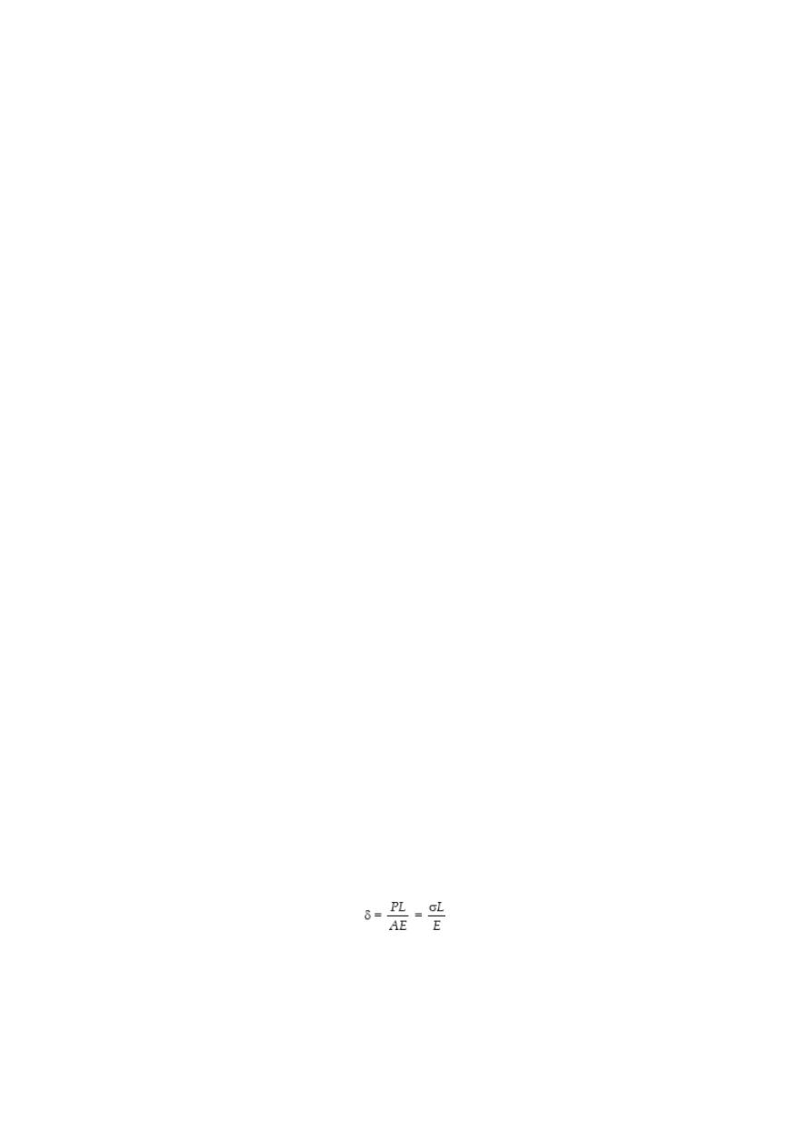
AXIAL DEFORMATION
In the linear portion of the stress-strain diagram, the tress is proportional to strain and
is given by
σ = Eε
since σ = P / A and εe = δ / L, then P / A = E δ / L. Solving for δ,
To use this formula, the load must be axial, the bar must have a uniform cross-sectional
area, and the stress must not exceed the proportional limit. If however, the cross-
sectional area is not uniform, the axial deformation can be determined by considering a
differential length and applying integration.
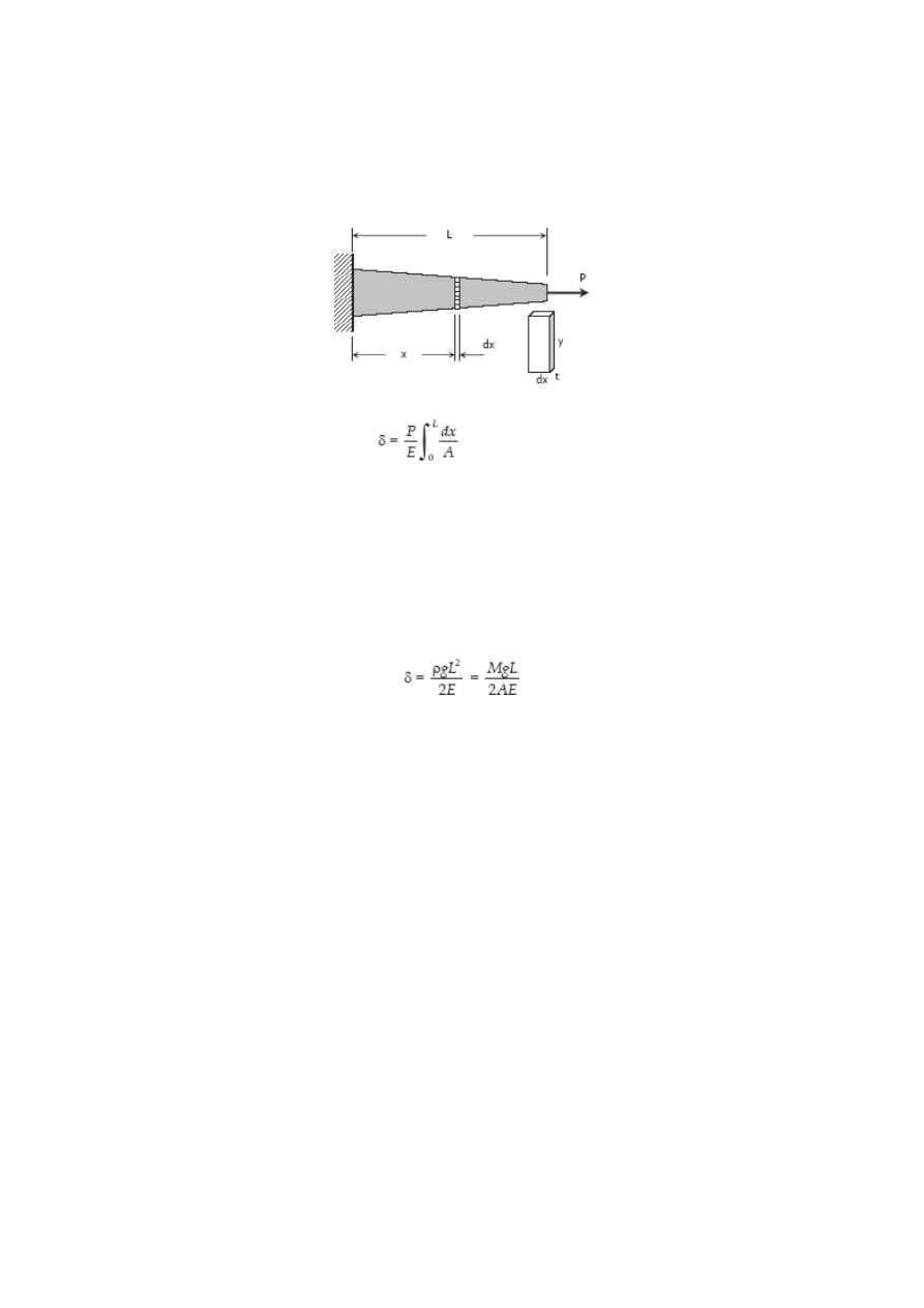
If however, the cross-sectional area is not uniform, the axial deformation can be
determined by considering a differential length and applying
integration.
where A = ty and y and t, if variable, must be expressed in terms of x.
For a rod of unit mass ρ suspended vertically from one end, the total elongation due to
its own weight is
where ρ is in kg/m
3
, L is the length of the rod in mm, M is the total mass of the rod in
kg, A is the cross-sectional area of the rod in mm
2
, and g = 9.81 m/s
2
.
STIFFNESS, k
Stiffness is the ratio of the steady force acting on an elastic body to the resulting
displacement. It has the unit of N/mm.
k = P / δ
SOLVED PROBLEMS IN AXIAL DEFORMATION
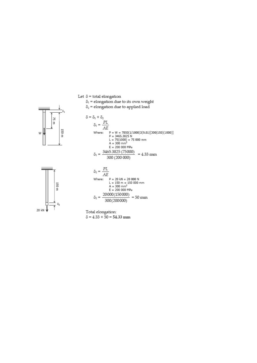
Problem 206
A steel rod having a cross-sectional area of 300 mm
2
and a length of 150 m is
suspended vertically from one end. It supports a tensile load of 20 kN at the lower end.
If the unit mass of steel is 7850 kg/m
3
and E = 200 × 10
3
MN/m
2
, find the total
elongation of the rod.
Solution 206
Problem 207
A steel wire 30 ft long, hanging vertically, supports a load of 500 lb. Neglecting the
weight of the wire, determine the required diameter if the stress is not to exceed 20 ksi
and the total elongation is not to exceed 0.20 in. Assume E = 29 × 10
6
psi.
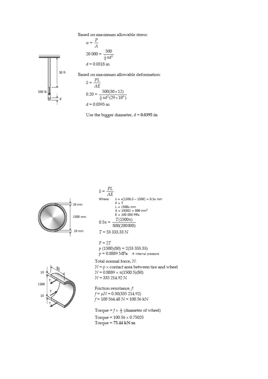
Solution 207
Problem 208
A steel tire, 10 mm thick, 80 mm wide, and 1500.0 mm inside diameter, is heated and
shrunk onto a steel wheel 1500.5 mm in diameter. If the coefficient of static friction is
0.30, what torque is required to twist the tire relative to the wheel? Neglect the
deformation of the wheel. Use E = 200 GPa.
Solution 208
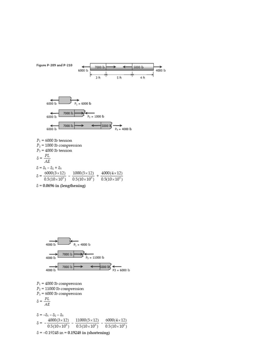
Problem 209
An aluminum bar having a cross-sectional area of 0.5 in
2
carries the axial loads applied
at the positions shown in Fig. P-209. Compute the total change in length of the bar if E
= 10 × 10
6
psi. Assume the bar is suitably braced to prevent lateral buckling.
Solution 209
Problem 210
Solve Prob. 209 if the points of application of the 6000-lb and the 4000-lb forces are
interchanged.
Solution 210
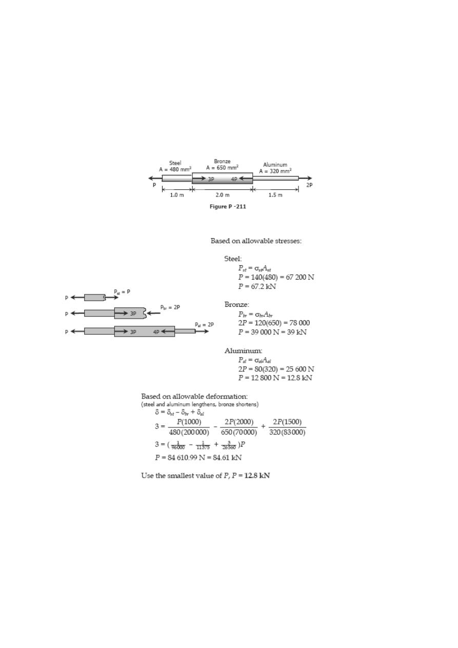
Problem 211
A bronze bar is fastened between a steel bar and an aluminum bar as shown in Fig. P-
211. Axial loads are applied at the positions indicated. Find the largest value of P that
will not exceed an overall deformation of 3.0 mm, or the following stresses: 140 MPa in
the steel, 120 MPa in the bronze, and 80 MPa in the aluminum. Assume that the
assembly is suitably braced to prevent buckling. Use E
st
= 200 GPa, E
al
= 70 GPa, and
E
br
= 83 GPa.
Solution 211
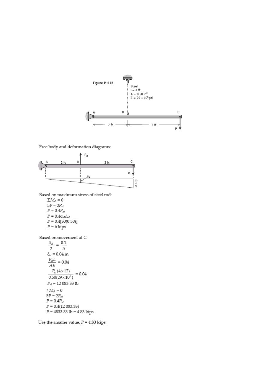
Problem 212
The rigid bar ABC shown in Fig. P-212 is hinged at A and supported by a steel rod at B.
Determine the largest load P that can be applied at C if the stress in the steel rod is
limited to 30 ksi and the vertical movement of end C must not exceed 0.10 in.
Solution 212
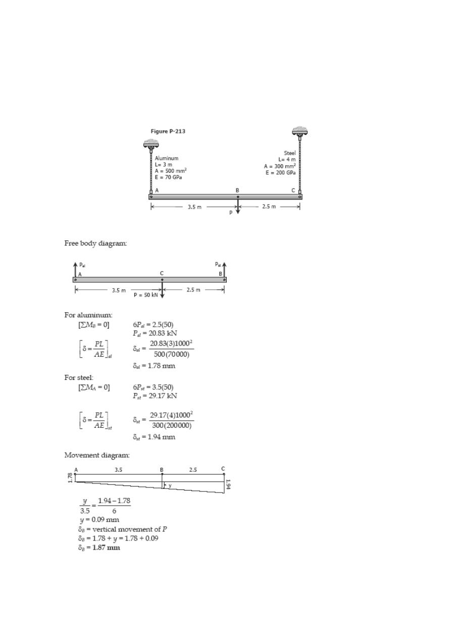
Problem 213
The rigid bar AB, attached to two vertical rods as shown in Fig. P-213, is horizontal
before the load P is applied. Determine the vertical movement of P if its magnitude is 50
kN.
Solution 213
Problem 214
The rigid bars AB and CD shown in Fig. P-214 are supported by pins at A and C and the
two rods. Determine the maximum force P that can be applied as shown if its vertical
movement is limited to 5 mm. Neglect the weights of all members.
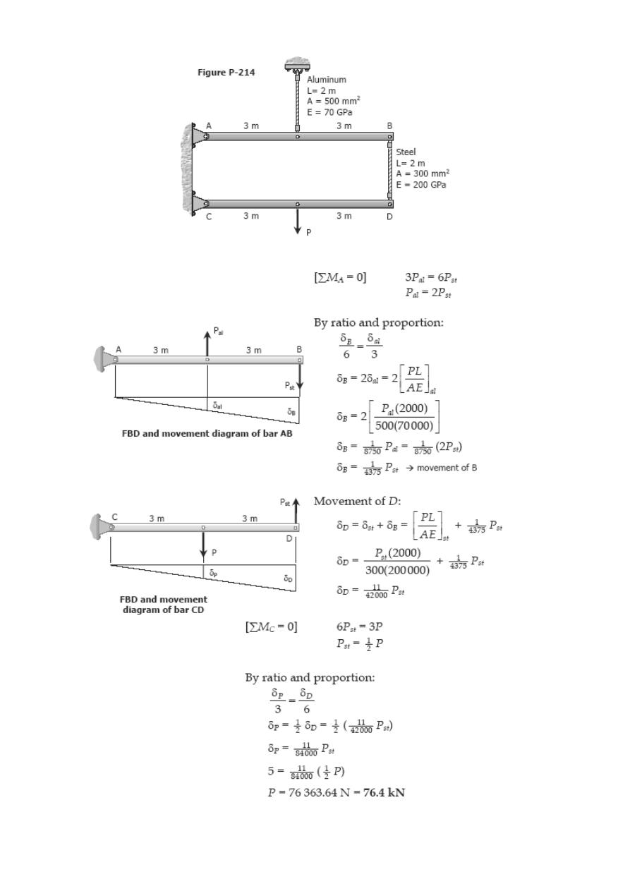
Solution 214
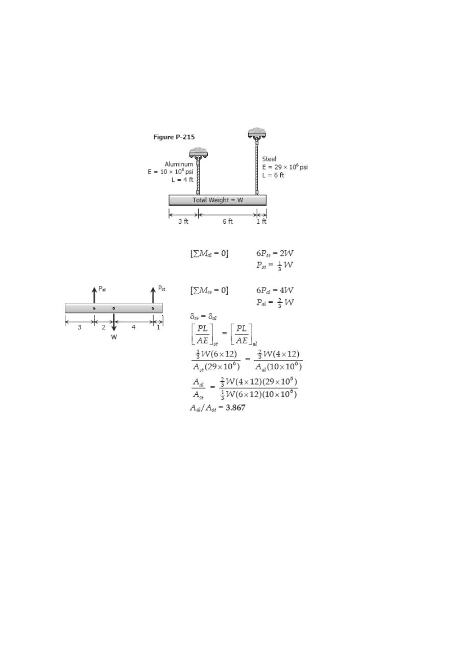
Problem 215
A uniform concrete slab of total weight W is to be attached, as shown in Fig. P-215, to
two rods whose lower ends are on the same level. Determine the ratio of the areas of
the rods so that the slab will remain level.
Solution 215
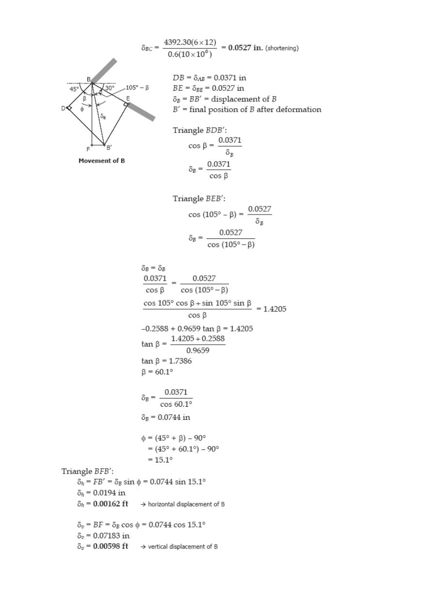
Problem 216
As shown in Fig. P-216, two aluminum rods AB and BC, hinged to rigid supports, are
pinned together at B to carry a vertical load P = 6000 lb. If each rod has a
crosssectional area of 0.60 in
2
and E = 10 × 10
6
psi, compute the elongation of each
rod and the horizontal and vertical displacements of point B. Assume α = 30° and θ =
30°.
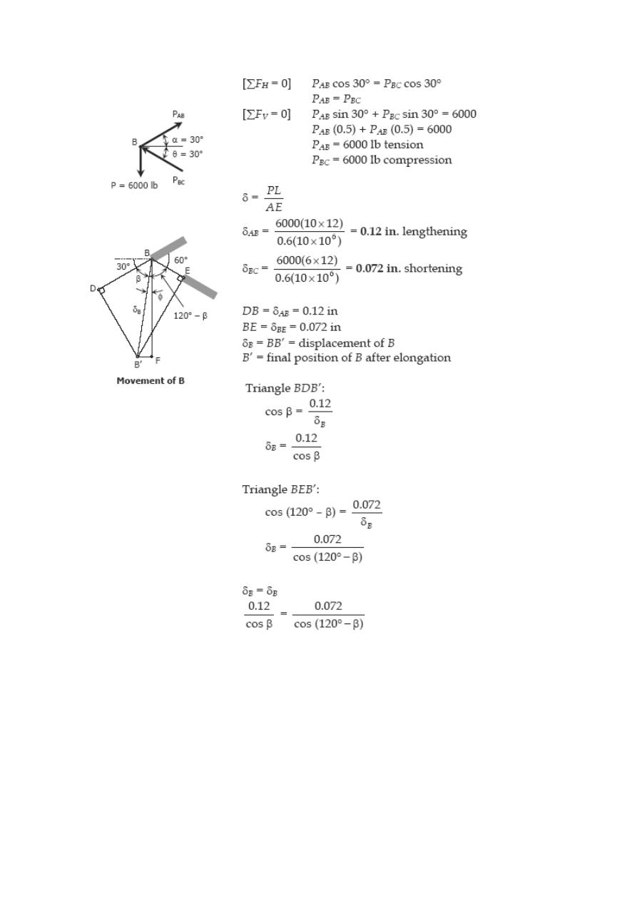
Solution 216
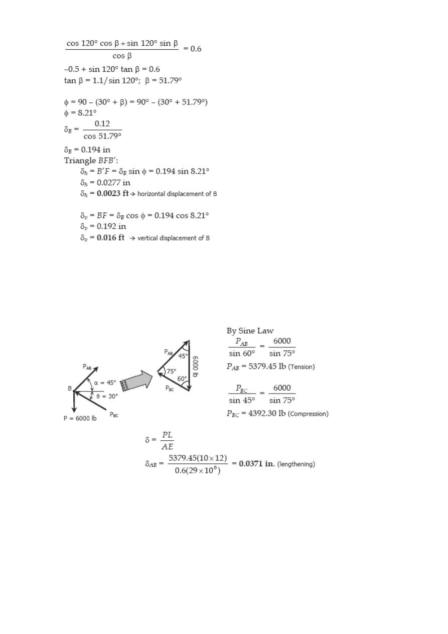
Problem 217
Solve Prob. 216 if rod AB is of steel, with E = 29 × 10
6
psi. Assume α = 45° and θ =
30°; all other data remain unchanged.
Solution 217
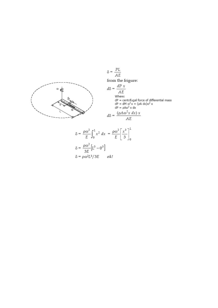
Problem 218
A uniform slender rod of length L and cross sectional area A is rotating in a horizontal
ertical axis through one end. If the unit mass of the
al
plane about a v
rod is ρ, and it is rotating at a constant angular velocity of ω rad/sec, show that the tot
elongation of the rod is ρω
2
L
3
/3E.
Solution 218
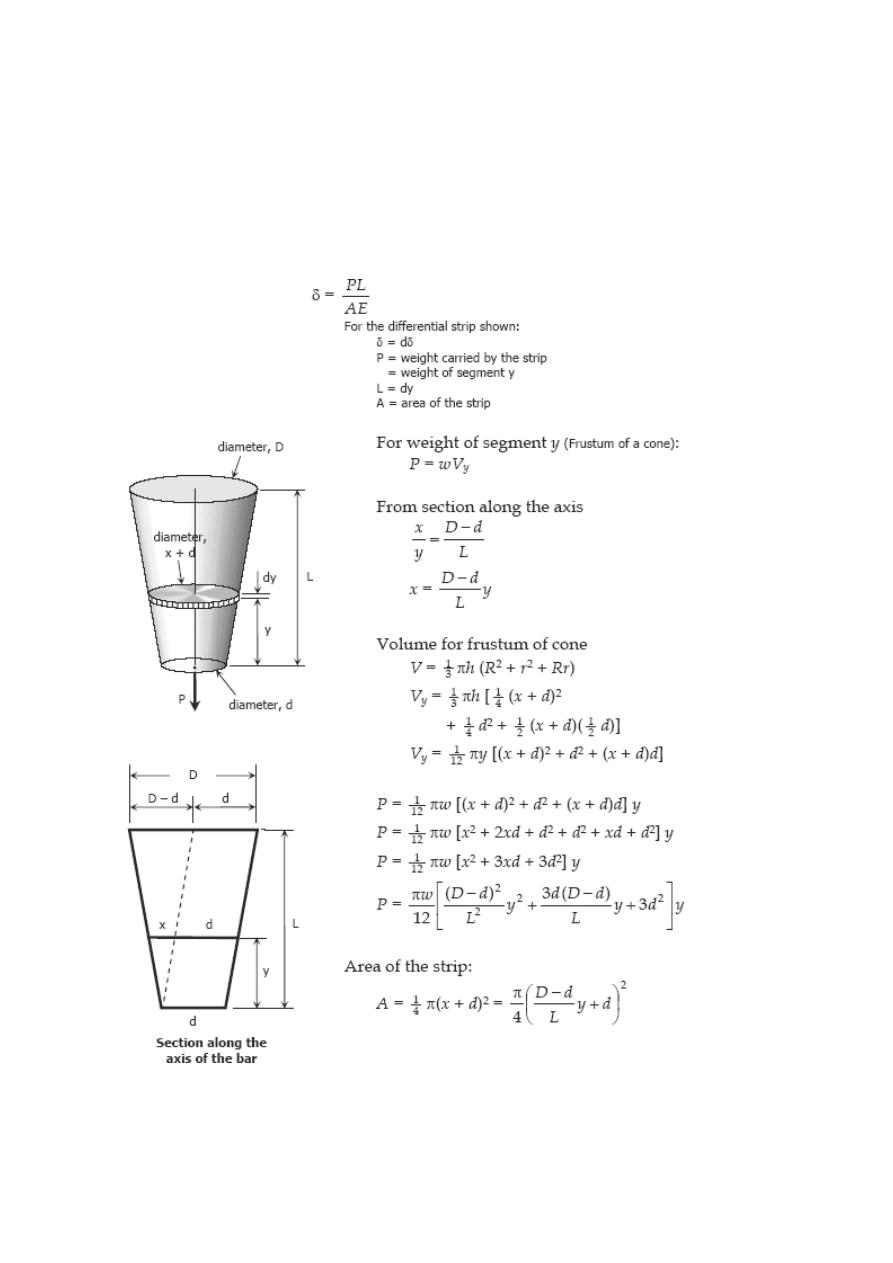
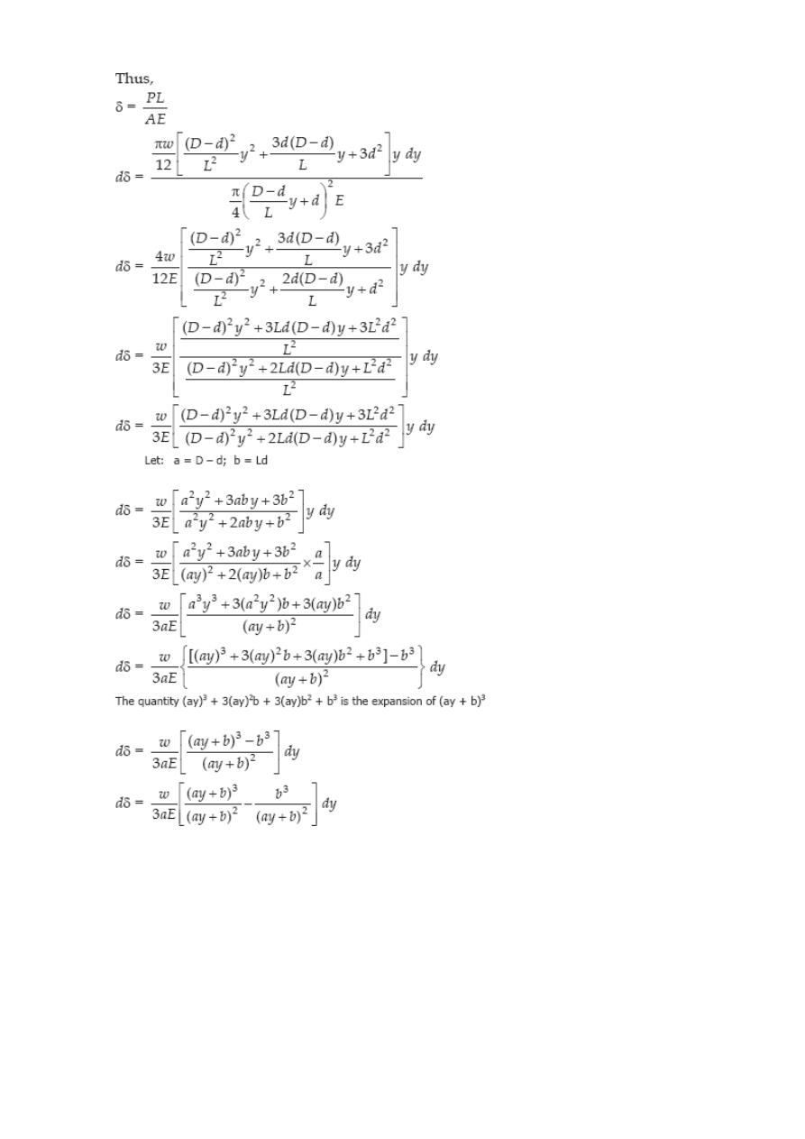
Problem 219
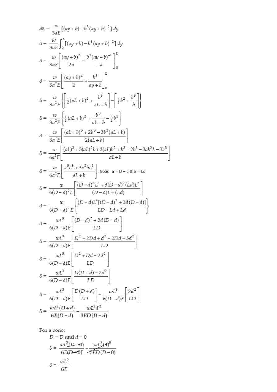
A round bar of length L, which tapers uniformly from a diameter D at one end to a
r d at the other, is suspended vertically from the large end. If w is the
e
smaller diamete
weight per unit volume, find the elongation of the rod caused by its own weight. Us
this result to determine the elongation of a cone suspended from its base.
Solution 219
SOLVED PROBLEMS IN STRAIN AND AXIAL DEFORMATION
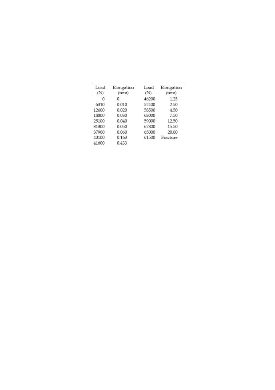
Problem 203
The following data were recorded during the tensile test of a 14-mm-diameter mild steel
rod. The gage length was 50 mm.
Plot the stress-strain diagram and determine the following mechanical properties: (a)
proportional limits; (b) modulus of elasticity; (c) yield point; (d) ultimate strength; and
(e) rupture strength.
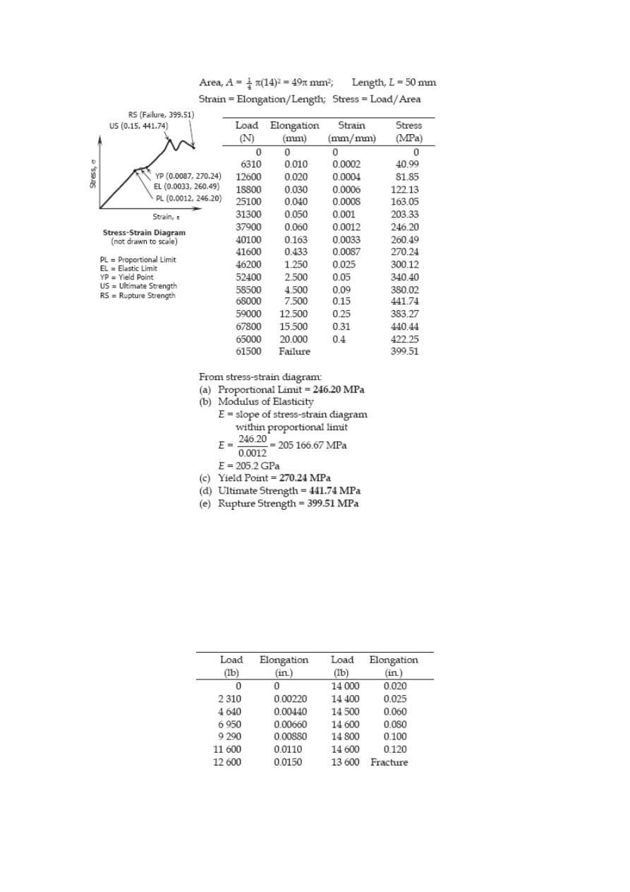
Solution 203
Problem 204
The following data were obtained during a tension test of an aluminum alloy. The initial
diameter of the test specimen was 0.505 in. and the gage length was
2.0 in.
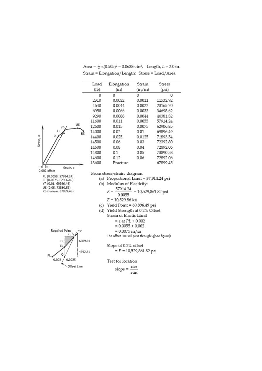
Plot the stress-strain diagram and determine the following mechanical properties: (a)
proportional limit; (b) modulus of elasticity; (c) yield point; (d) yield strength at 0.2%
offset; (e) ultimate strength; and (f) rupture strength.
Solution 204
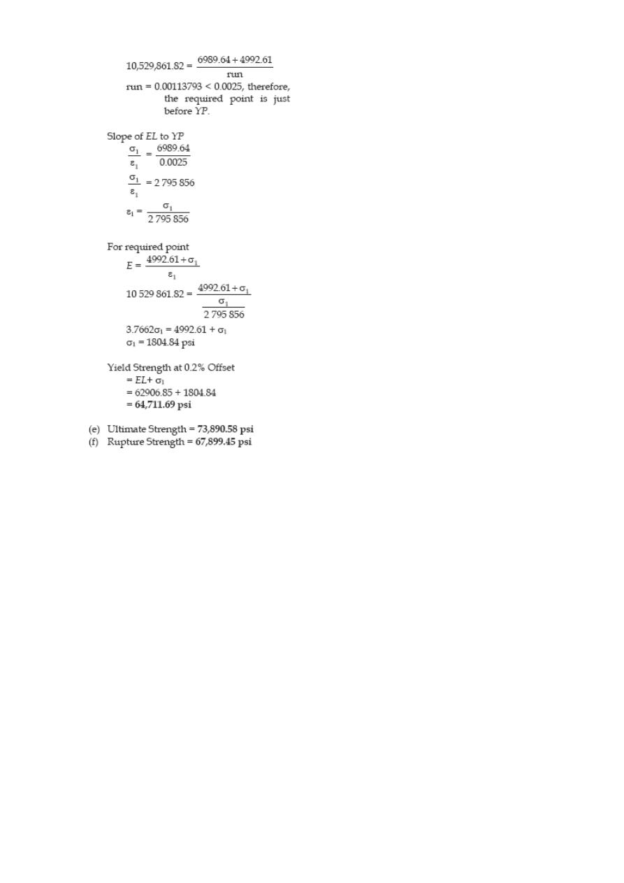
Problem 205
A uniform bar of length L, cross-sectional area A, and unit mass ρ is suspended
vertically from one end. Show that its total elongation is δ = ρgL
2
/ 2E. If the total mass
of the bar is M, show also that δ = MgL/2AE.
Solution 205
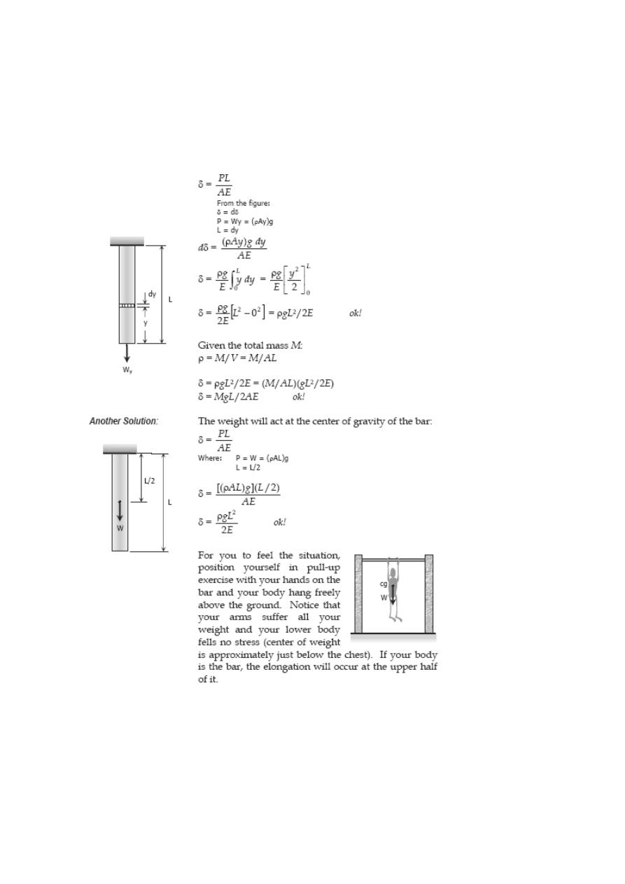
Shearing Deformation
Shearing forces cause shearing deformation. An element subject to shear does not
change in length but undergoes a change in shape.
The change in angle at the corner of an original rectangular element is called the shear
strain and is expressed as
The ratio of the shear stress τ and the shear strain γ is called the modulus of elasticity
in shear or modulus of rigidity and is denoted as G, in MPa.
The relationship between the shearing deformation and the applied shearing force is
where V is the shearing force acting over an area A
s
.
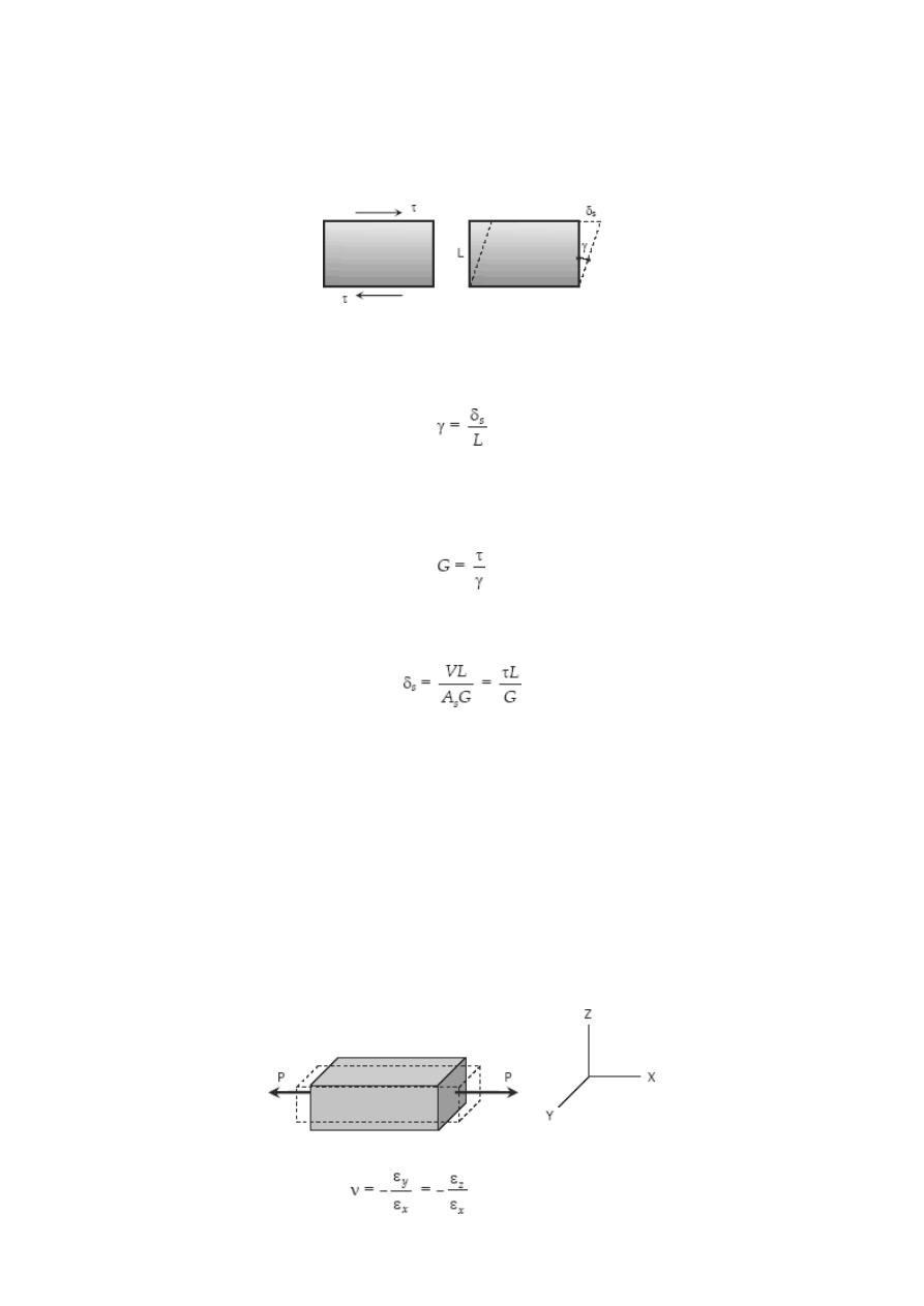
Poisson's Ratio
When a bar is subjected to a tensile loading there is an increase in length of the bar in
the direction of the applied load, but there is also a decrease in a lateral dimension
perpendicular to the load. The ratio of the sidewise deformation (or strain) to the
longitudinal deformation (or strain) is called the Poisson's ratio and is denoted by ν. For
most steel, it lies in the range of 0.25 to 0.3, and 0.20 for concrete.
where ε
x
is strain in the x-direction and ε
y
and ε
z
are the strains in the perpendicular
direction. The negative sign indicates a decrease in the transverse dimension when ε
x
is
positive.
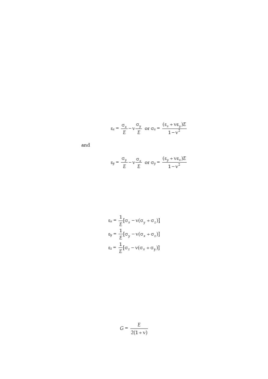
BIAXIAL DEFORMATION
If an element is subjected simultaneously by ensile stresses, σ
x
and σ
y
, in the x and y
directions, the strain in the x-direction is σ
x
/ E and the strain in the y direction is σ
y
/ E.
Simultaneously, the stress in the y direction will produce a lateral contraction on the x
x
direction of the amount -ν ε
y
or -ν σ
y
/E. The resulting strain in the x direction will be
TRIAXIAL DEFORMATION
If an element is subjected simultaneously by three mutually perpendicular normal
stresses σ
x
, σ
y
, and σ
z
, which are accompanied by strains ε
x
, ε
y
, and ε
z
, respectively,
Tensile stresses and elongation are taken as positive. Compressive stresses and
contraction are taken as negative.
Relationship Between E, G, and
ν
The relationship between modulus of elasticity E, shear modulus G and Poisson's ratio ν
is:
Bulk Modulus of Elasticity or Modulus of Volume Expansion, K
The bulk modulus of elasticity K is a measure of a resistance of a material to change in
volume without change in shape or form. It is given as
where V is the volume and ΔV is change in volume. The ratio ΔV / V is called volumetric
strain and can be expressed as
Solved Problems in Shearing Deformation
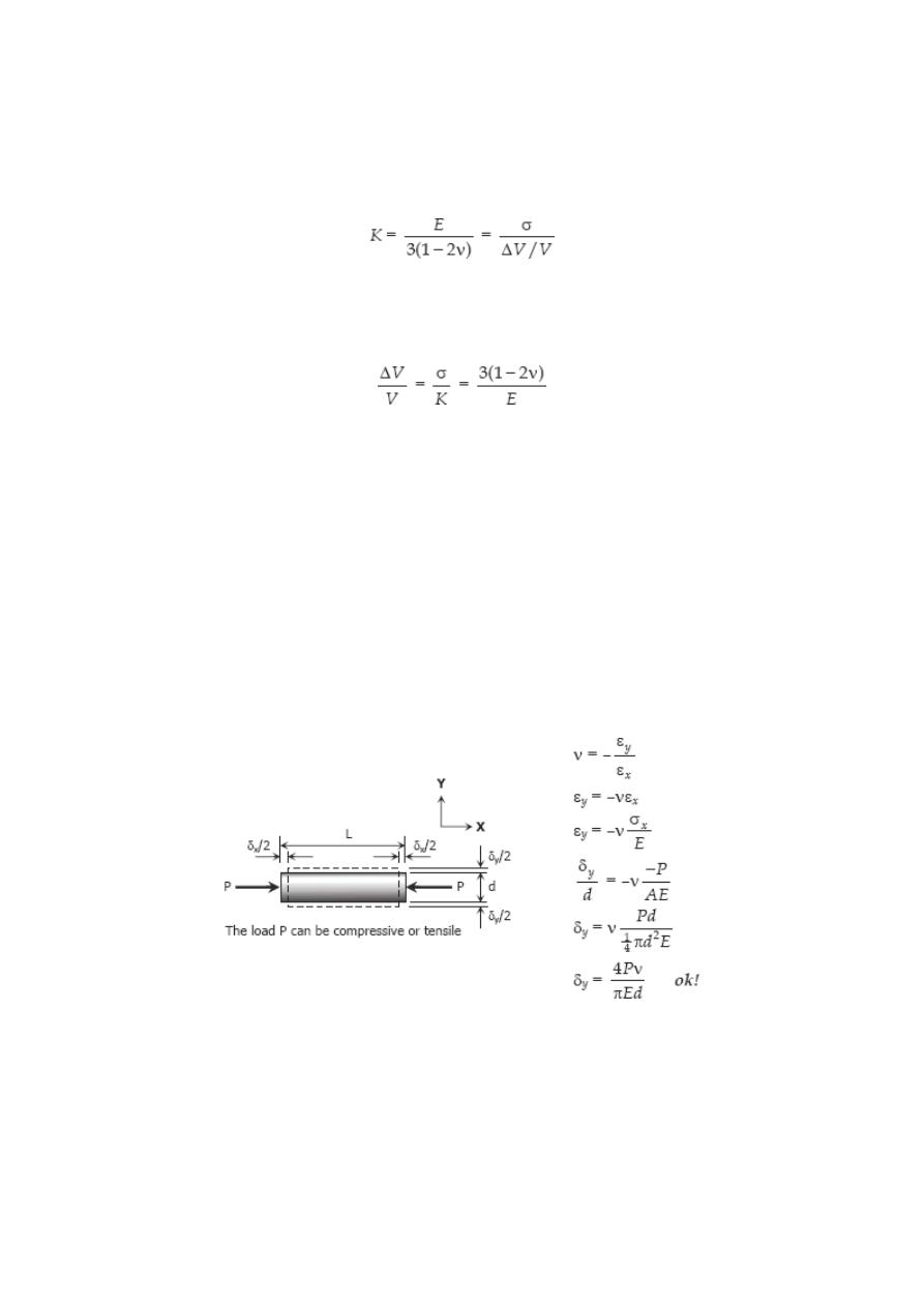
Problem 222
A solid cylinder of diameter d carries an axial load P. Show that its change in diameter is
4Pν / πEd.
Solution 222
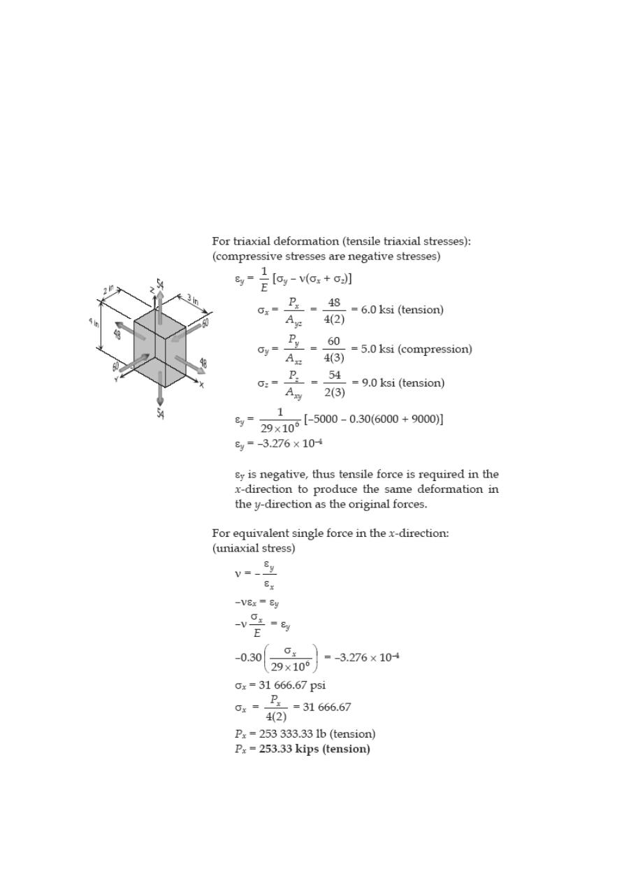
Problem 223
A rectangular steel block is 3 inches long in the x direction, 2 inches long in the y
direction, and 4 inches long in the z direction. The block is subjected to a triaxial loading
of three uniformly distributed forces as follows: 48 kips tension in the x direction, 60
kips compression in the y direction, and 54 kips tension in the z direction. If ν = 0.30
and E = 29 × 10
6
psi, determine the single uniformly distributed load in the x direction
that would produce the same deformation in the y direction as the original loading.
Solution 223
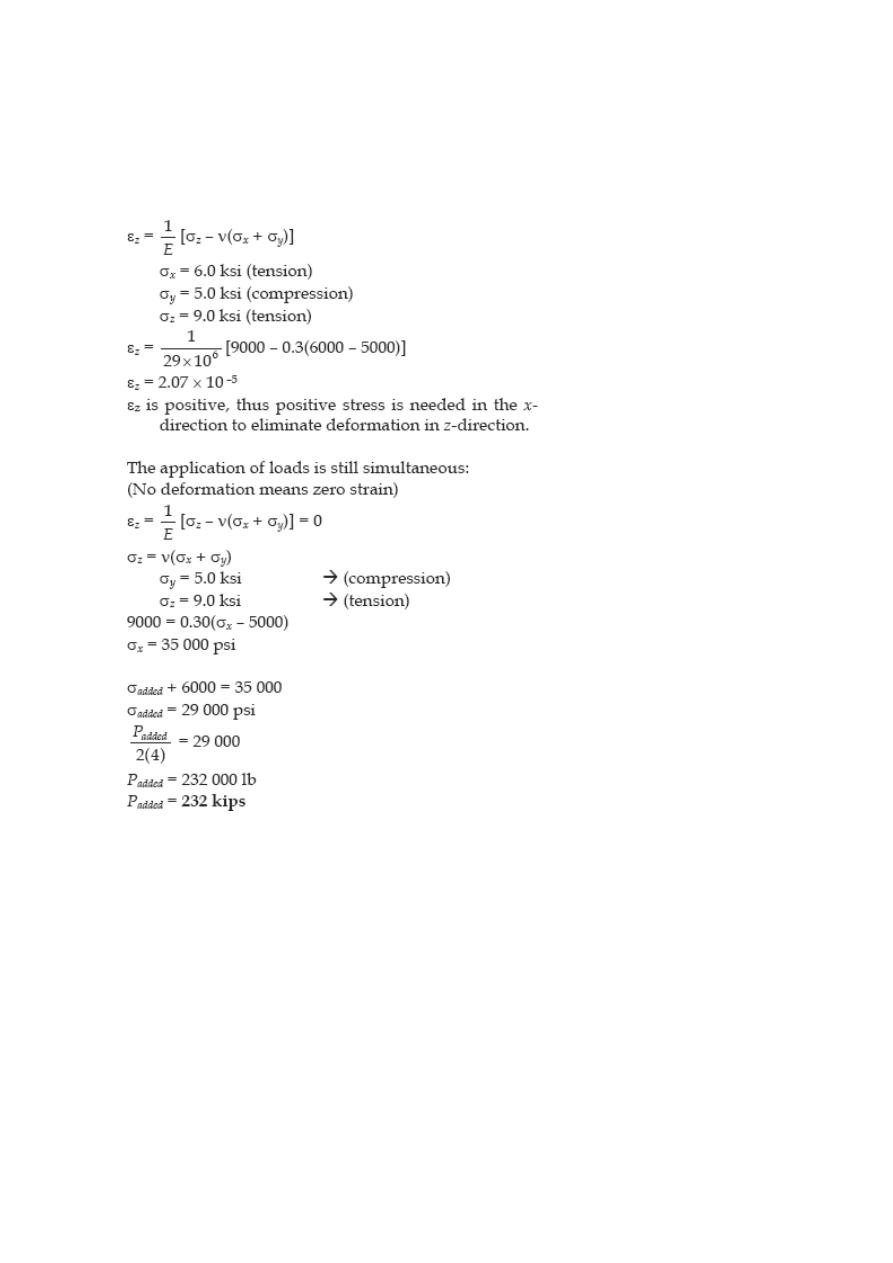
Problem 224
For the block loaded triaxially as described in Prob. 223, find the uniformly distributed
load that must be added in the x direction to produce no deformation in the z direction.
Solution 224
Problem 225
A welded steel cylindrical drum made of a 10-mm plate has an internal diameter of 1.20
m. Compute the change in diameter that would be caused by an internal pressure of 1.5
MPa. Assume that Poisson's ratio is 0.30 and E = 200 GPa.
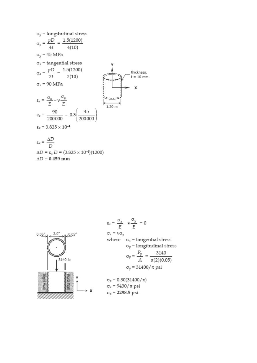
Solution 225
Problem 226
A 2-in.-diameter steel tube with a wall thickness of 0.05 inch just fits in a rigid hole.
Find the tangential stress if an axial compressive load of 3140 lb is applied. Assume ν =
0.30 and neglect the possibility of buckling.
Solution 226
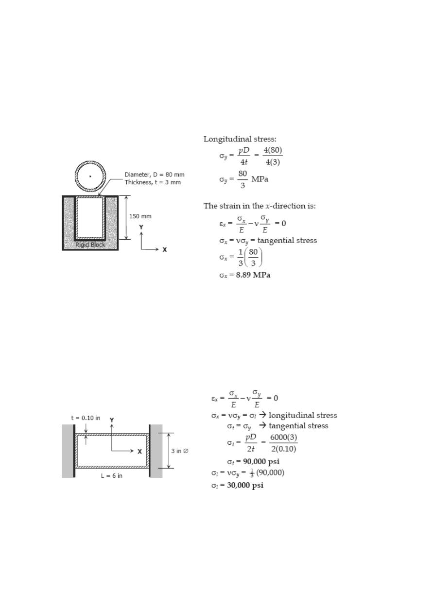
Problem 227
A 150-mm-long bronze tube, closed at its ends, is 80 mm in diameter and has a wall
thickness of 3 mm. It fits without clearance in an 80-mm hole in a rigid
block. The tube is then subjected to an internal pressure of 4.00 MPa. Assuming ν = 1/3
and E = 83 GPa, determine the tangential stress in the tube.
Solution 227
Problem 228
A 6-in.-long bronze tube, with closed ends, is 3 in. in diameter with a wall thickness of
0.10 in. With no internal pressure, the tube just fits between two rigid end walls.
Calculate the longitudinal and tangential stresses for an internal pressure of 6000 psi.
Assume ν = 1/3 and E = 12 × 10
6
psi.
Solution 228
Statically Indeterminate Members
When the reactive forces or the internal resisting forces over a cross section exceed the
number of independent equations of equilibrium, the structure is called statically
indeterminate. These cases require the use of additional relations that depend on the
elastic deformations in the members.
Solved Problems in Statically Indeterminate Members
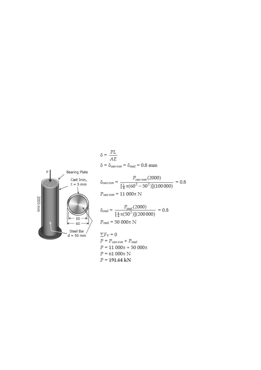
Problem 233
A steel bar 50 mm in diameter and 2 m long is surrounded by a shell of a cast iron 5
mm thick. Compute the load that will compress the combined bar a total of 0.8 mm in
the length of 2 m. For steel, E = 200 GPa, and for cast iron, E = 100 GPa.
Solution 233
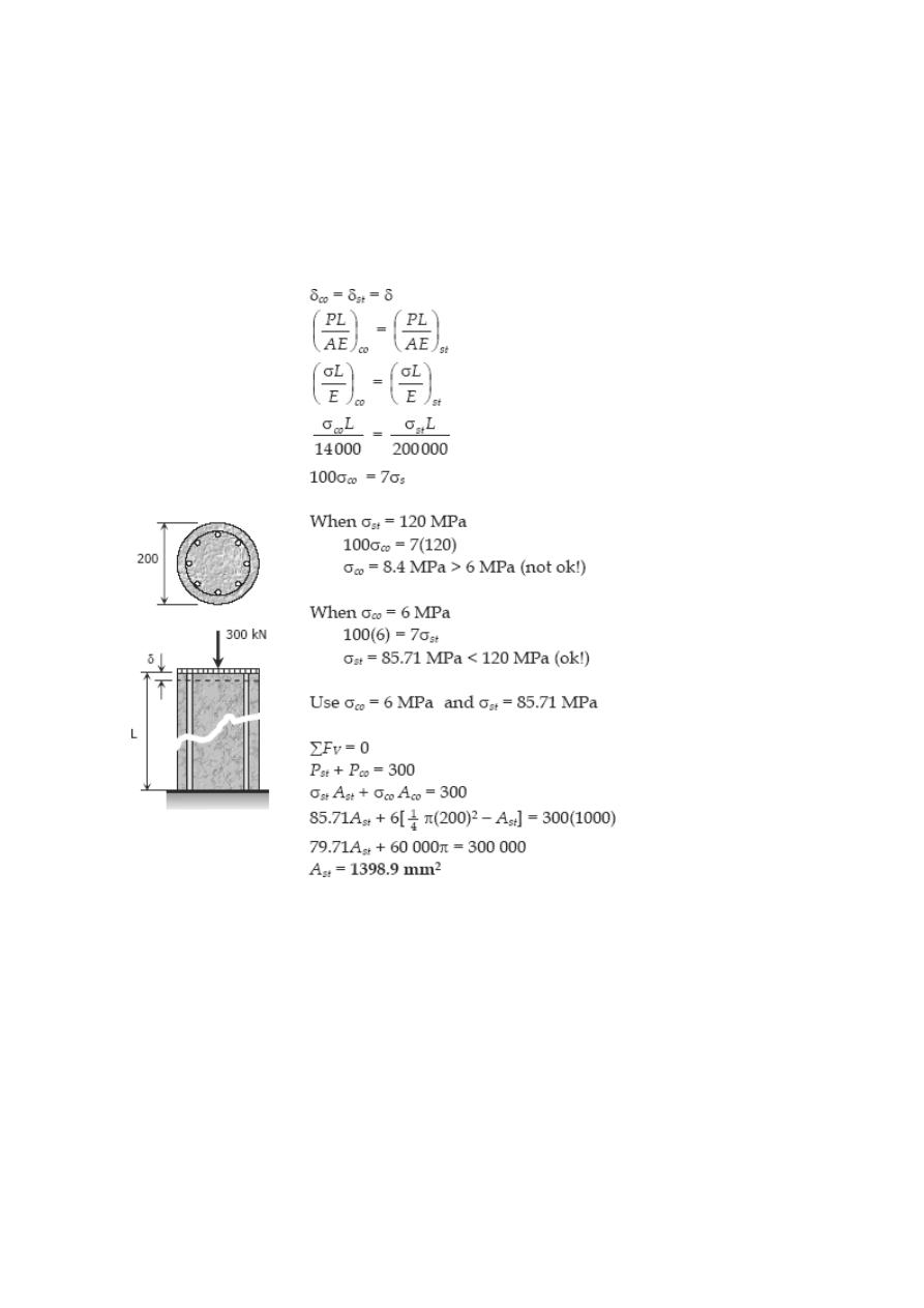
Problem 234
A reinforced concrete column 200 mm in diameter is designed to carry an axial
compressive load of 300 kN. Determine the required area of the reinforcing steel if the
allowable stresses are 6 MPa and 120 MPa for the concrete and steel, respectively. Use
E
co
= 14 GPa and E
st
= 200 GPa.
Solution 234
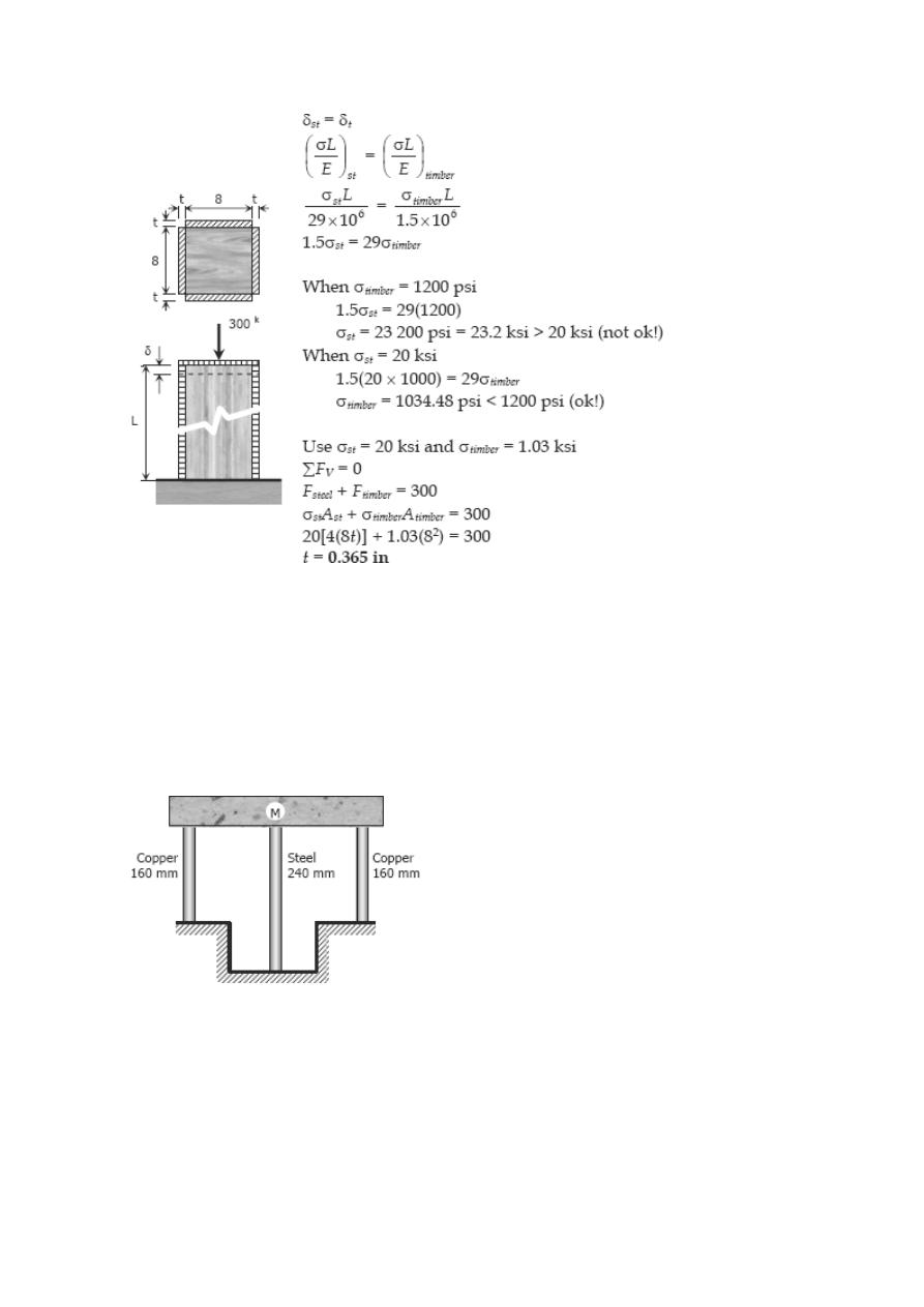
Problem 235
A timber column, 8 in. × 8 in. in cross section, is reinforced on each side by a steel
plate 8 in. wide and t in. thick. Determine the thickness t so that the column will
support an axial load of 300 kips without exceeding a maximum timber stress of 1200
psi or a maximum steel stress of 20 ksi. The moduli of elasticity are 1.5 × 10
6
psi for
timber, and 29 × 10
6
psi for steel.
Solution 235
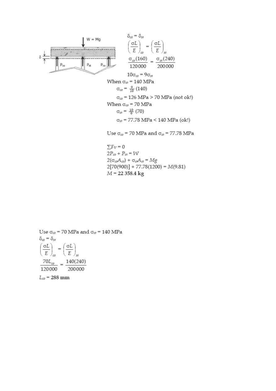
Problem 236
A rigid block of mass M is supported by three symmetrically spaced rods as shown in fig
P-236. Each copper rod has an area of 900 mm
2
; E = 120 GPa; and the allowable stress
is 70 MPa. The steel rod has an area of 1200 mm
2
; E = 200 GPa; and the allowable
stress is 140 MPa. Determine the largest mass M which can be supported.
Figure P-236 and P-237
Solution 236
Problem 237
In Prob. 236, how should the lengths of the two identical copper rods be changed so
that each material will be stressed to its allowable limit?
Solution 237
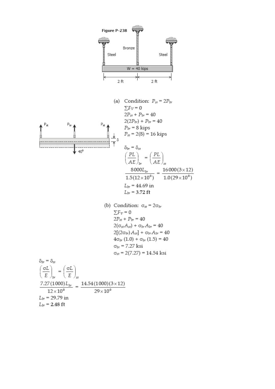
Problem 238
The lower ends of the three bars in Fig. P-238 are at the same level before the uniform
rigid block weighing 40 kips is attached. Each steel bar has a length of 3 ft, and area of
1.0 in.
2
, and E = 29 × 10
6
psi. For the bronze bar, the area is 1.5 in.
2
and E = 12 × 10
6
psi. Determine (a) the length of the bronze bar so that the load on each steel bar is
twice the load on the bronze bar, and (b) the length of the bronze that will make the
steel stress twice the bronze stress.
Solution 238
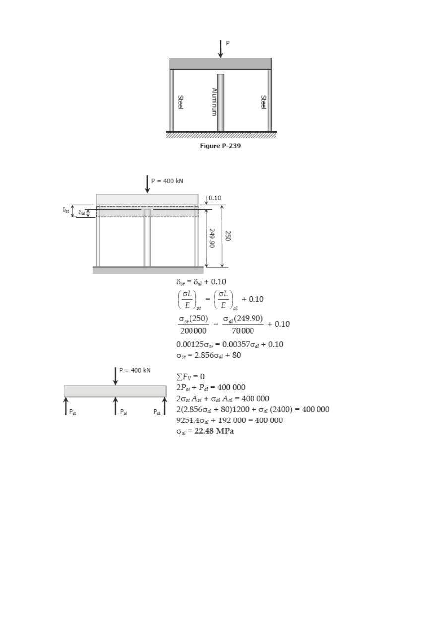
Problem 239
The rigid platform in Fig. P-239 has negligible mass and rests on two steel bars, each
250.00 mm long. The center bar is aluminum and 249.90 mm long. Compute the stress
in the aluminum bar after the center load P = 400 kN has been applied. For each steel
bar, the area is 1200 mm
2
and E = 200 GPa. For the aluminum bar, the area is 2400
mm
2
and E = 70 GPa.
Solution 239
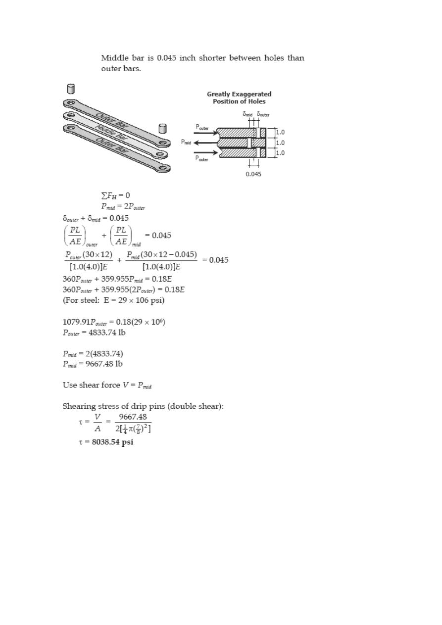
Problem 240
Three steel eye-bars, each 4 in. by 1 in. in section, are to be assembled by driving rigid
7/8-in.-diameter drift pins through holes drilled in the ends of the bars. The center-line
spacing between the holes is 30 ft in the two outer bars, but 0.045 in. shorter in the
middle bar. Find the shearing stress developed in the drip pins. Neglect local
deformation at the holes.
Solution 240
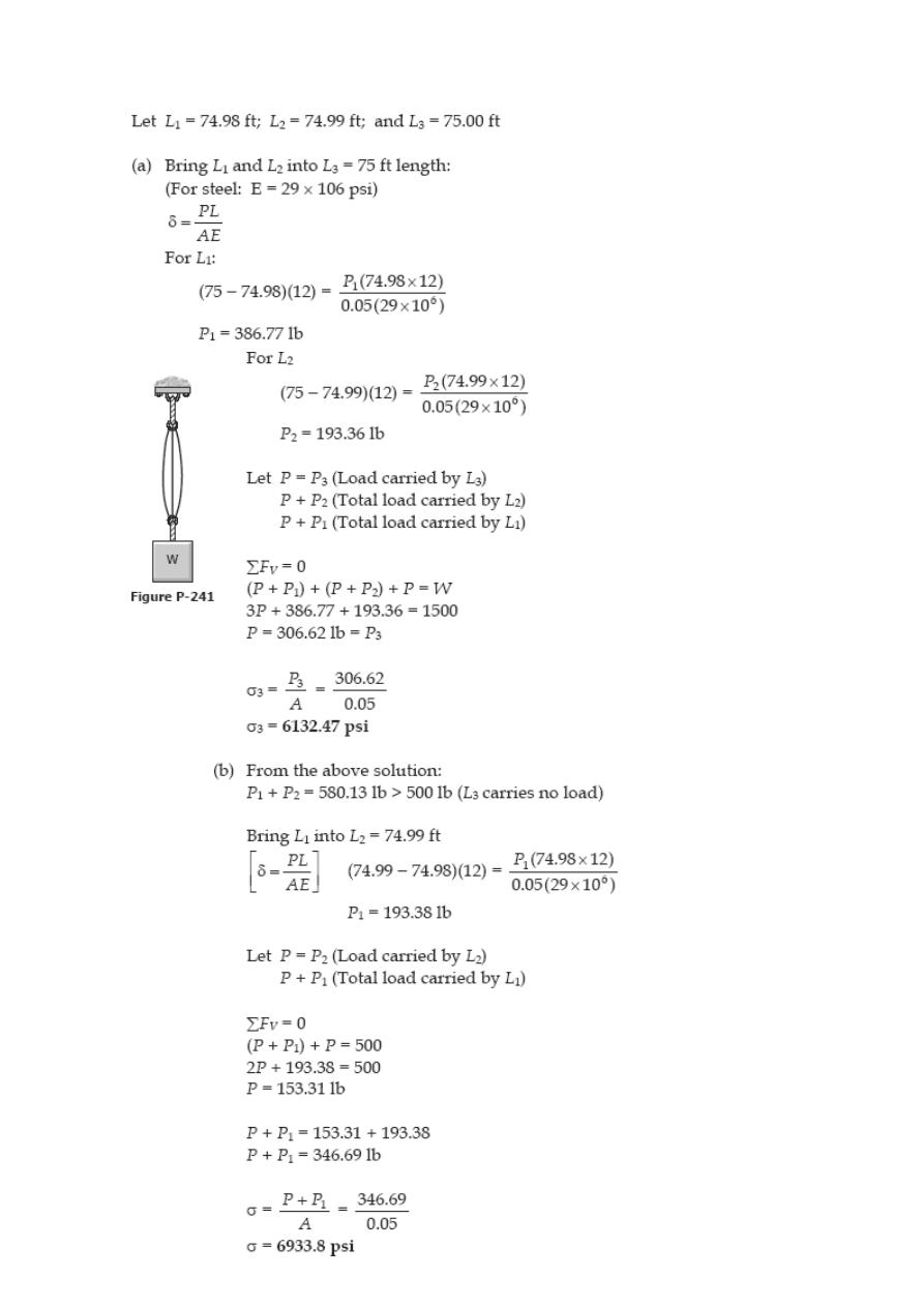
Problem 241
As shown in Fig. P-241, three steel wires, each 0.05 in.
2
in area, are used to lift a load
W = 1500 lb. Their unstressed lengths are 74.98 ft, 74.99 ft, and 75.00 ft. (a) What
stress exists in the longest wire? (b) Determine the stress in the shortest wire if W =
500 lb.
Solution 241
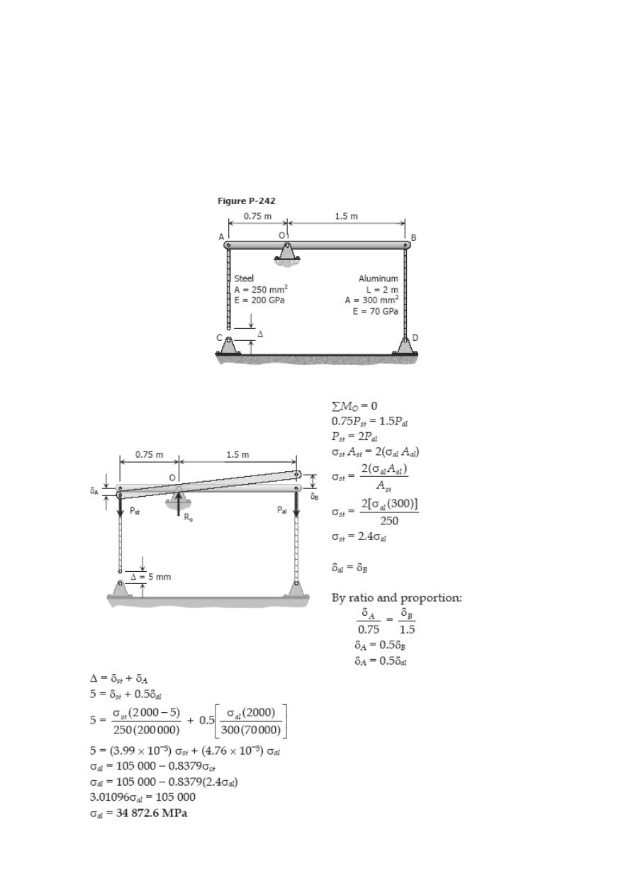
Problem 242
The assembly in Fig. P-242 consists of a light rigid bar AB, pinned at O, that is attached
to the steel and aluminum rods. In the position shown, bar AB is horizontal and there is
a gap, Δ = 5 mm, between the lower end of the steel rod and its pin support at C.
Compute the stress in the aluminum rod when the lower end of the steel rod is attached
to its support.
Solution 242
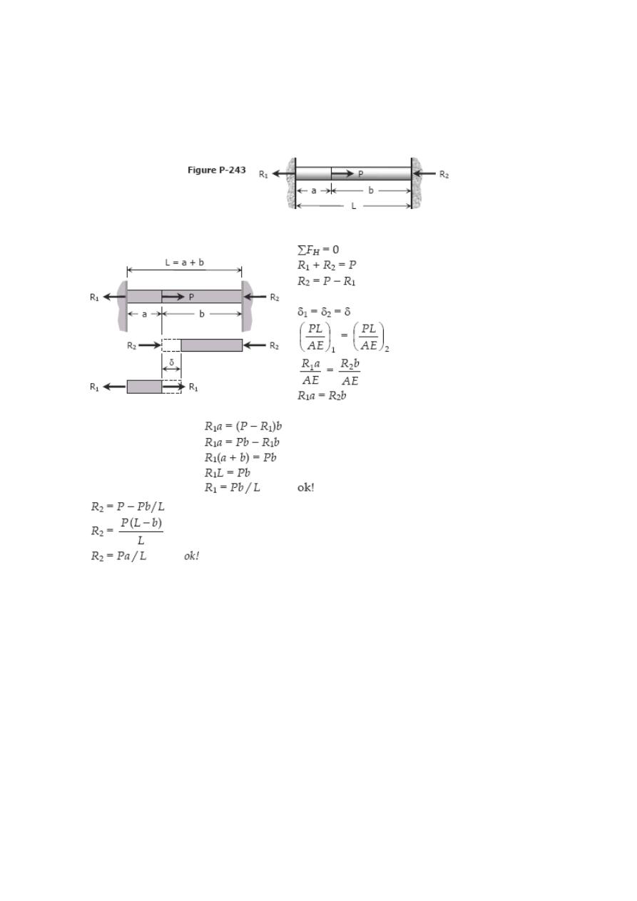
Problem 243
A homogeneous rod of constant cross section is attached to unyielding supports. It
carries an axial load P applied as shown in Fig. P-243. Prove that the reactions are given
by R
1
= Pb/L and R
2
= Pa/L.
Solution 243
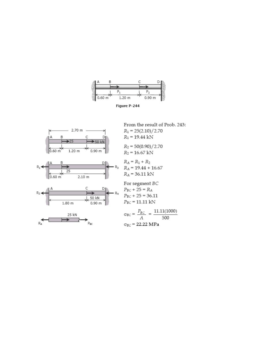
Problem 244
A homogeneous bar with a cross sectional area of 500 mm
2
is attached to rigid
supports. It carries the axial loads P1 = 25 kN and P2 = 50 kN, applied as shown in Fig.
P-244. Determine the stress in segment BC. (Hint: Use the results of Prob. 243, and
compute the reactions caused by P
1
and P
2
acting separately. Then use the principle of
superposition to compute the reactions when both loads are applied.)
Solution 244
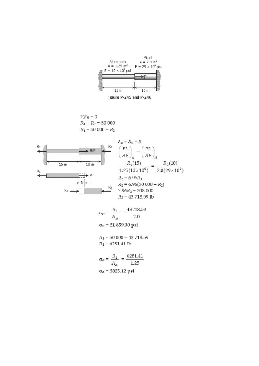
Problem 245
The composite bar in Fig. P-245 is firmly attached to unyielding supports. Compute the
stress in each material caused by the application of the axial load P = 50 kips.
Solution 245
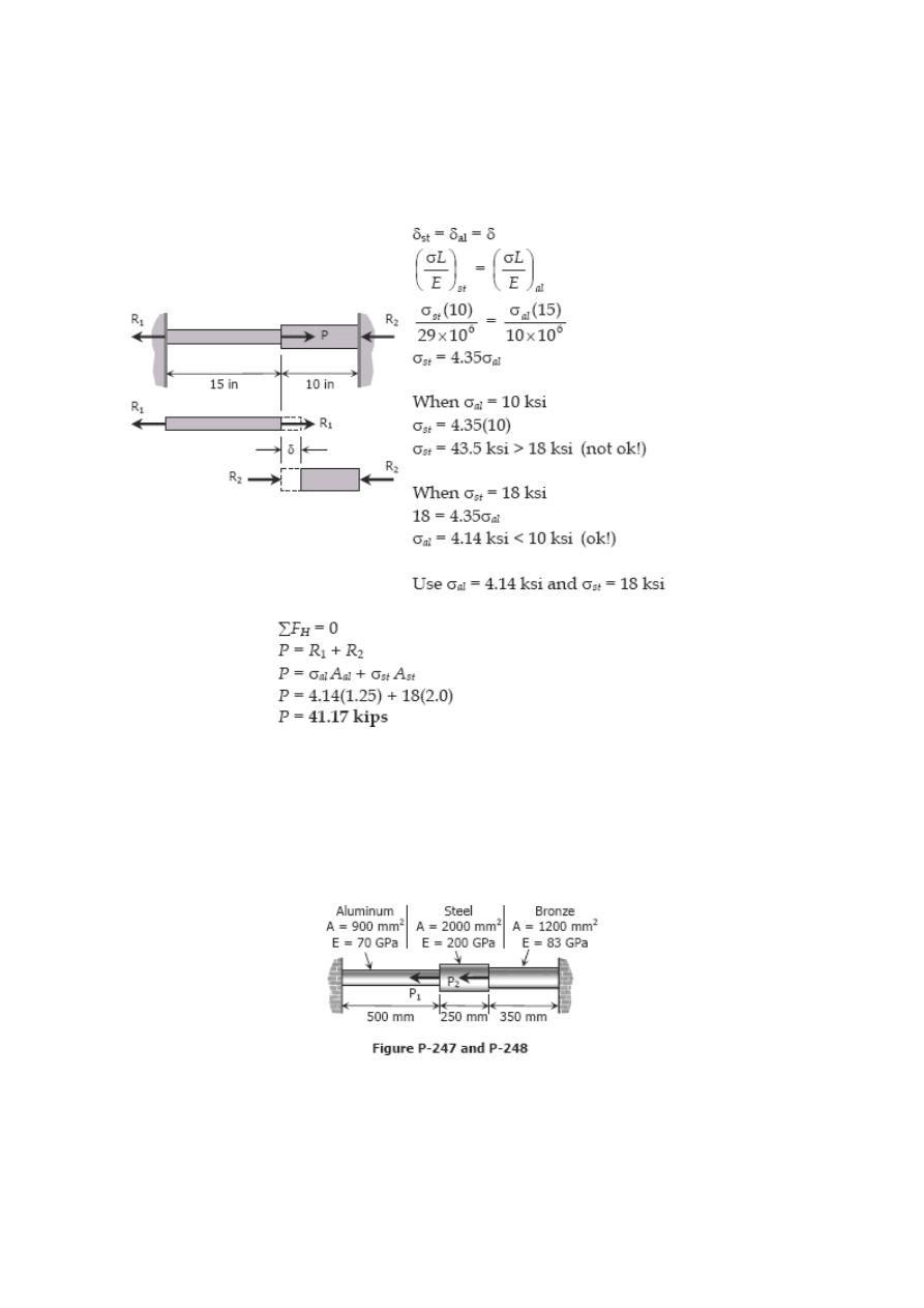
Problem 246
Referring to the composite bar in Prob. 245, what maximum axial load P can be applied
if the allowable stresses are 10 ksi for aluminum and 18 ksi for steel.
Solution 246
Problem 247
The composite bar in Fig. P-247 is stress-free before the axial loads P1 and P2 are
applied. Assuming that the walls are rigid, calculate the stress in each material if P
1
=
150 kN and P
2
= 90 kN.
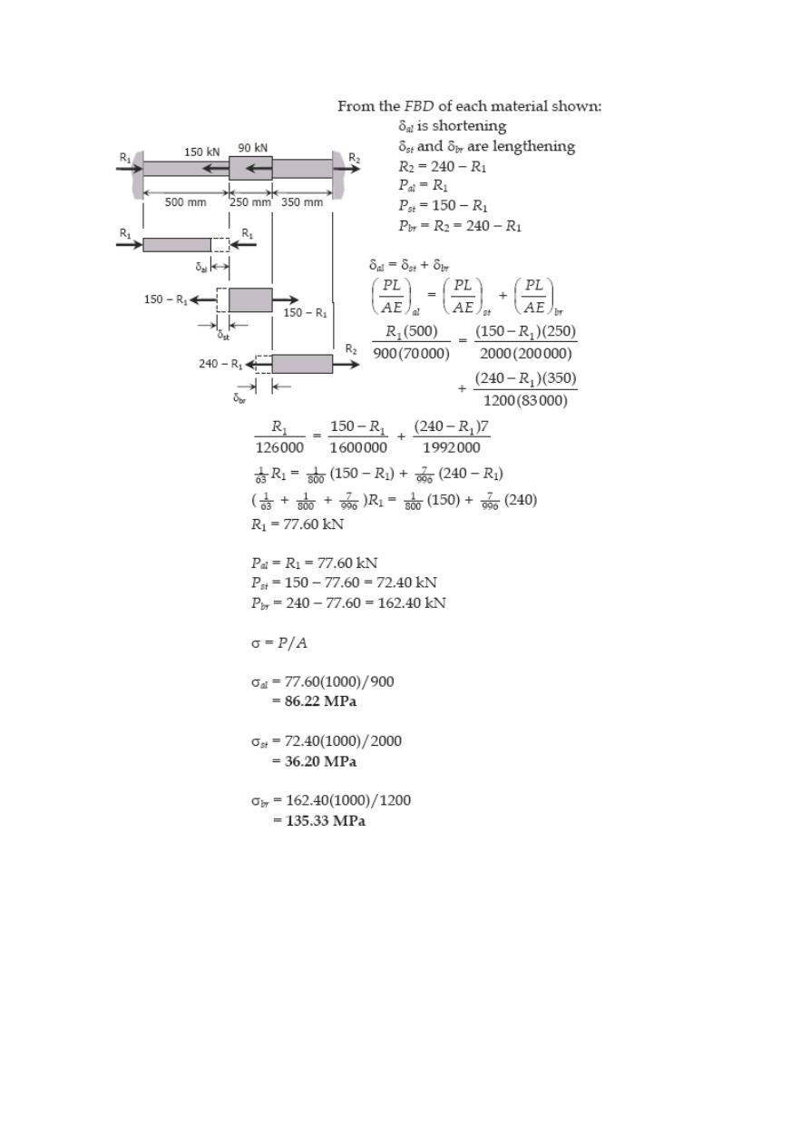
Solution 247
Problem 248
Solve Prob. 247 if the right wall yields 0.80 mm.
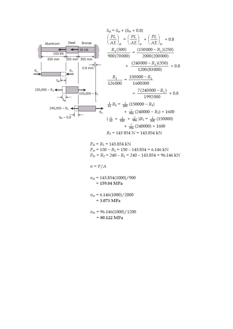
Solution 248
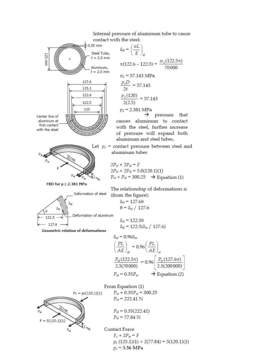
Problem 249
There is a radial clearance of 0.05 mm when a steel tube is placed over an aluminum
tube. The inside diameter of the aluminum tube is 120 mm, and the wall thickness of
each tube is 2.5 mm. Compute the contact pressure and tangential stress in each tube
when the aluminum tube is subjected to an internal pressure of 5.0 MPa.
Solution 249
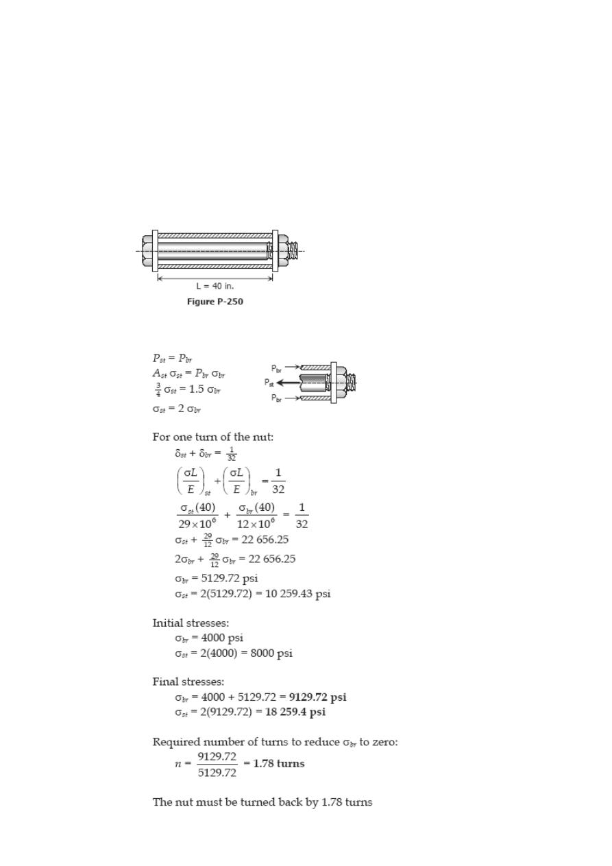
Problem 250
In the assembly of the bronze tube and steel bolt shown in Fig. P-250, the pitch of the
bolt thread is p = 1/32 in.; the cross-sectional area of the bronze tube is 1.5 in.
2
and of
steel bolt is ¾ in.
2
The nut is turned until there is a compressive stress of 4000 psi in
the bronze tube. Find the stresses if the nut is given one additional turn. How many
turns of the nut will reduce these stresses to zero? Use Ebr = 12 × 10
6
psi and Est = 29
× 10
6
psi.
Solution 250
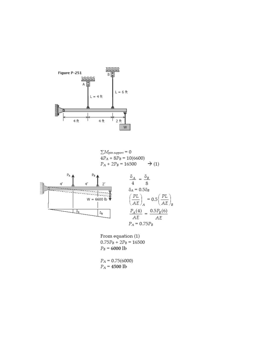
Problem 251
The two vertical rods attached to the light rigid bar in Fig. P-251 are identical except for
length. Before the load W was attached, the bar was horizontal and the rods were
stress-free. Determine the load in each rod if W = 6600 lb.
Solution 251
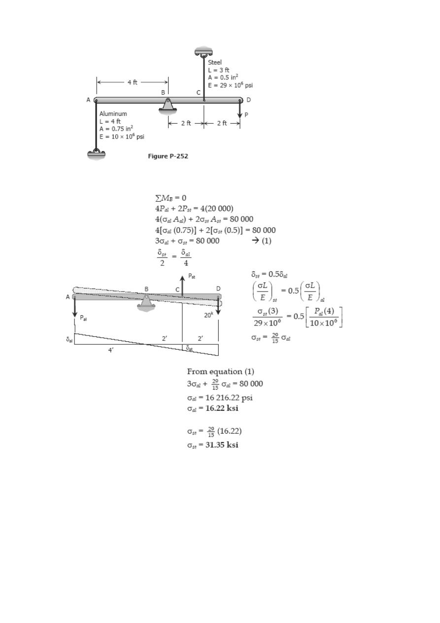
Problem 252
The light rigid bar ABCD shown in Fig. P-252 is pinned at B and connected to two
vertical rods. Assuming that the bar was initially horizontal and the rods stress-free,
determine the stress in each rod after the load after the load P = 20 kips is applied.
Solution 252
Problem 253
As shown in Fig. P-253, a rigid beam with negligible weight is pinned at one end and
attached to two vertical rods. The beam was initially horizontal before the load W = 50
kips was applied. Find the vertical movement of W.
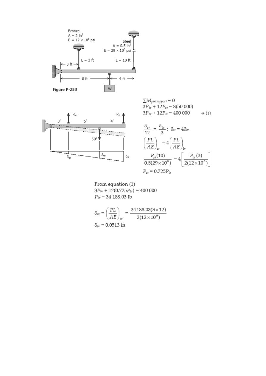
Solution 253
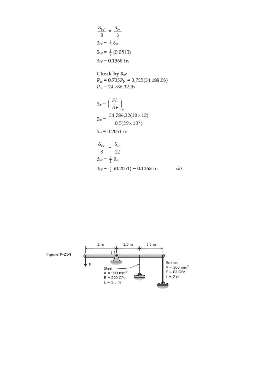
Problem 254
As shown in Fig. P-254, a rigid bar with negligible mass is pinned at O and attached to
two vertical rods. Assuming that the rods were initially tress-free, what maximum load P
can be applied without exceeding stresses of 150 MPa in the steel rod and 70 MPa in the
bronze rod.
Solution 254
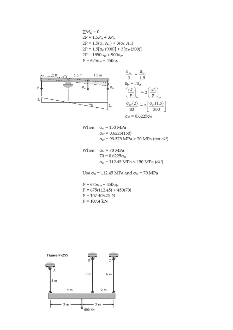
Problem 255
Shown in Fig. P-255 is a section through a balcony. The total uniform load of 600 kN is
supported by three rods of the same area and material. Compute the load in each rod.
Assume the floor to be rigid, but note that it does not necessarily remain horizontal.
Solution 255
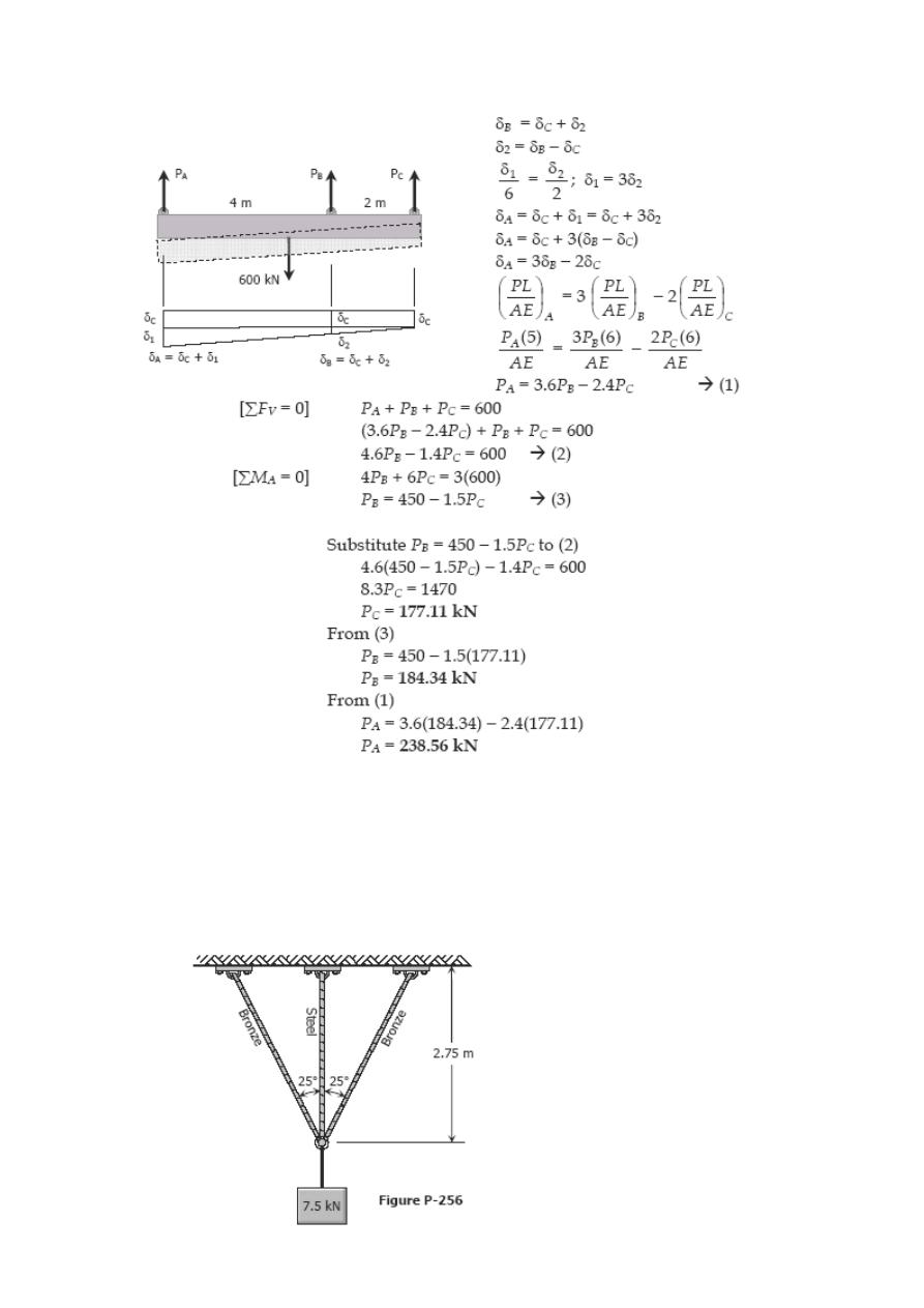
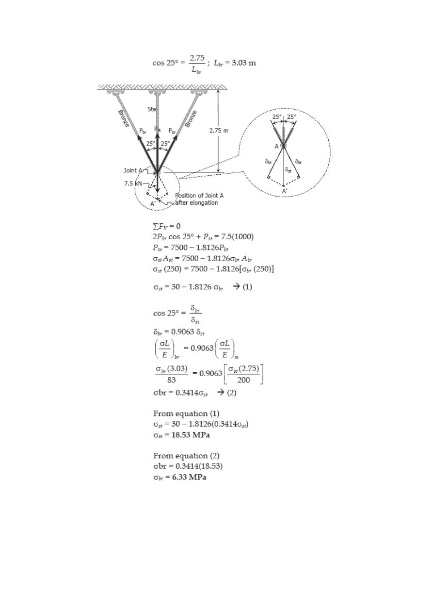
Problem 256
Three rods, each of area 250 mm2, jointly support a 7.5 kN load, as shown in Fig. P-
256. Assuming that there was no slack or stress in the rods before the load was applied,
find the stress in each rod. Use E
st
= 200 GPa and E
br
= 83 GPa.
Solution 256
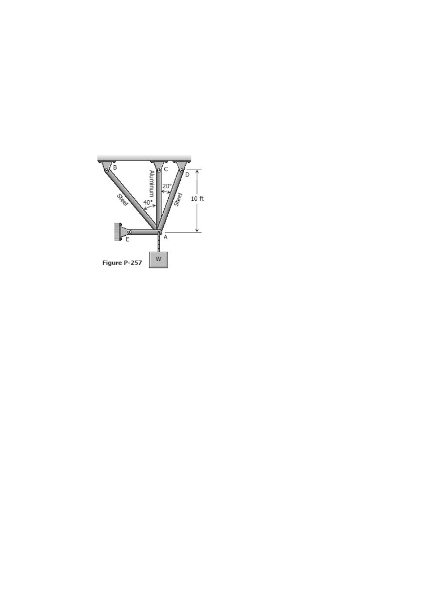
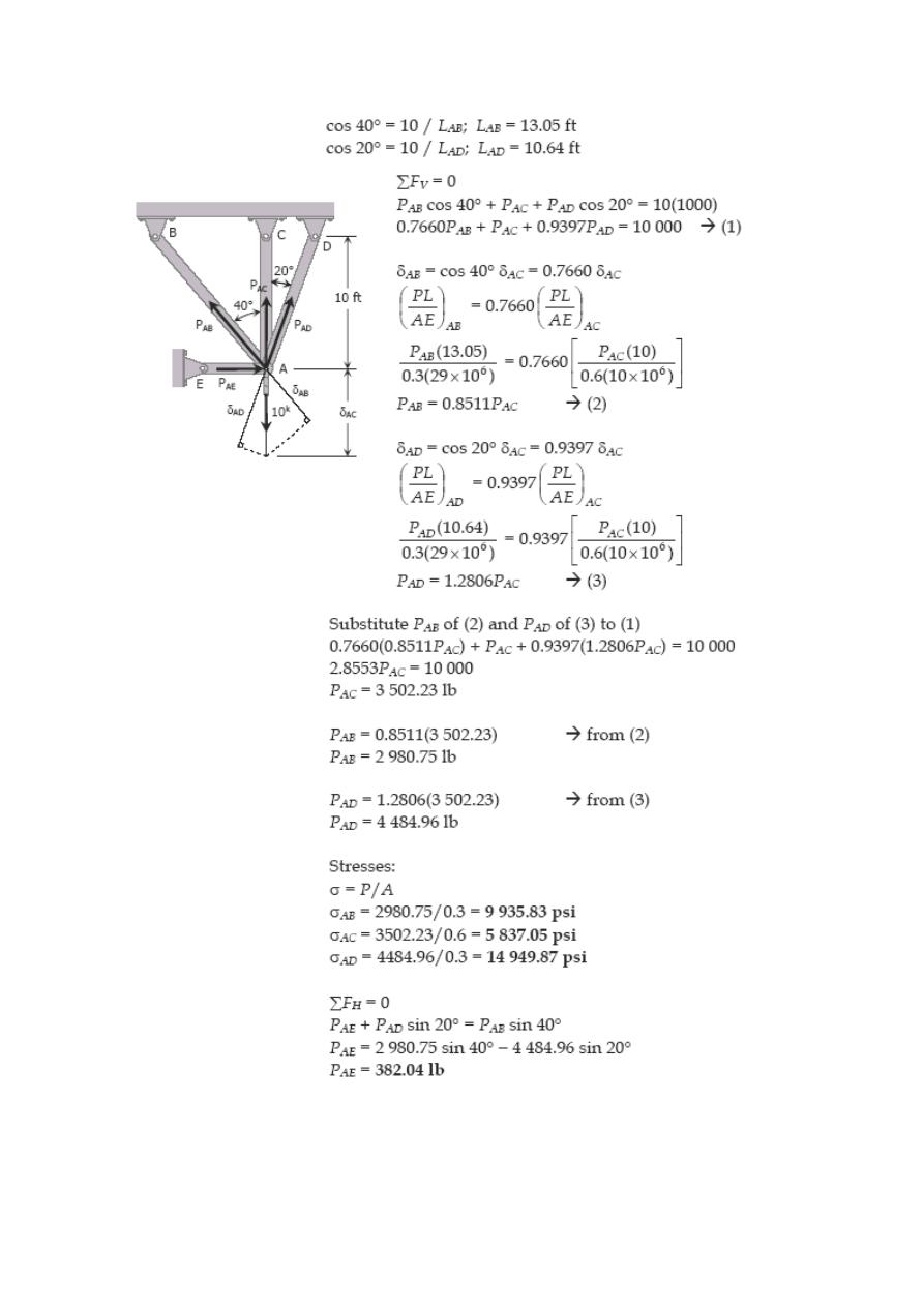
Problem 257
Three bars AB, AC, and AD are pinned together as shown in Fig. P-257. Initially, the
assembly is stressfree. Horizontal movement of the joint at A is prevented by a short
horizontal strut AE. Calculate the stress in each bar and the force in the strut AE when
the assembly is used to support the load W = 10 kips. For each steel bar, A = 0.3 in.
2
and E = 29 × 10
6
psi. For the aluminum bar, A = 0.6 in.
2
and E = 10 × 10
6
psi.
Solution 257
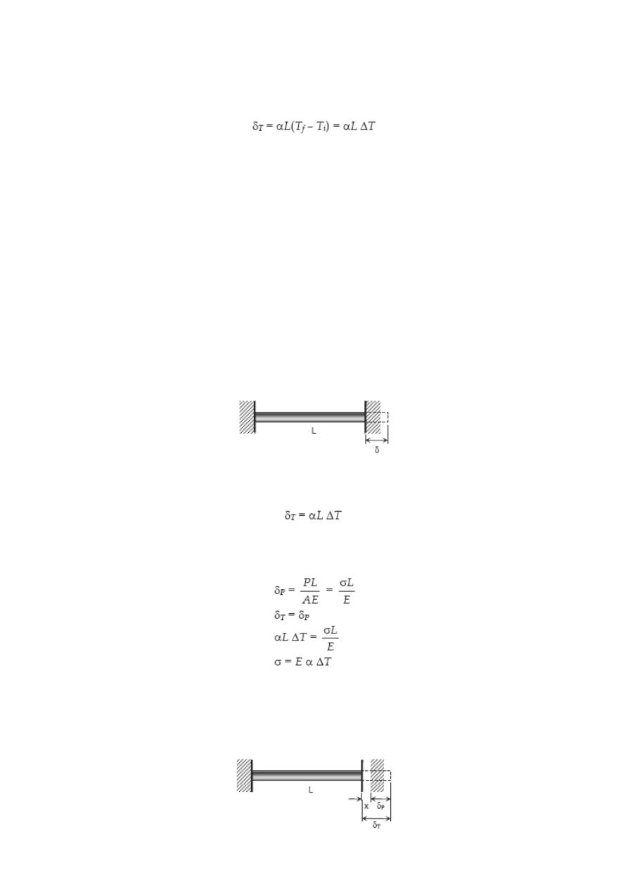
Thermal Stress
Temperature changes cause the body to expand or contract. The amount δ
T
, is given by
where α is the coefficient of thermal expansion in m/m°C, L is the length in meter, and
T
i
and T
f
are the initial and final temperatures, respectively in °C.
For steel, α = 11.25 × 10
–6
/ °C.
If temperature deformation is permitted to occur freely, no load or stress will be
induced in the structure. In some cases where temperature deformation is not
permitted, an internal stress is created. The internal stress created is termed as thermal
stress.
For a homogeneous rod mounted between unyielding supports as shown, the thermal
stress is computed as:
deformation due to temperature changes;
deformation due to equivalent axial stress;
where σ is the thermal stress in MPa and E is the modulus of elasticity of the rod in MPa.
If the wall yields a distance of x as shown, the following calculations will be made:
where σ represents the thermal stress.
Take note that as the temperature rises above the normal, the rod will be in
compression, and if the temperature drops below the normal, the rod is in tension.
Solved Problems in Thermal Stress
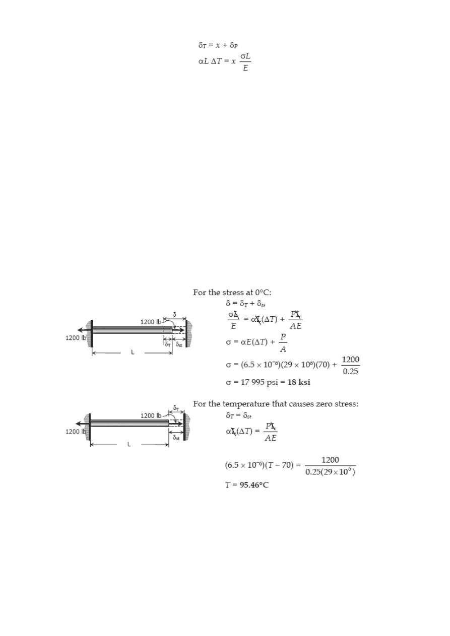
Problem 261
A steel rod with a cross-sectional area of 0.25 in
2
is stretched between two fixed points.
The tensile load at 70°F is 1200 lb. What will be the stress at 0°F? At what temperature
will the stress be zero? Assume α = 6.5 × 10
-6
in / (in·°F) and E = 29 × 10
6
psi.
Solution 261
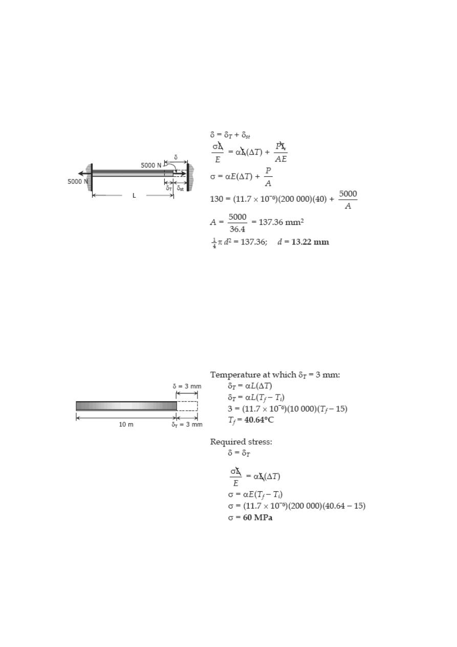
Problem 262
A steel rod is stretched between two rigid walls and carries a tensile load of 5000 N at
20°C. If the allowable stress is not to exceed 130 MPa at -20°C, what is the minimum
diameter of the rod? Assume α = 11.7 µm/(m·°C) and E = 200 GPa.
Solution 262
Problem 263
Steel railroad reels 10 m long are laid with a clearance of 3 mm at a temperature of
15°C. At what temperature will the rails just touch? What stress would be induced in the
rails at that temperature if there were no initial clearance? Assume α = 11.7 µm/(m·°C)
and E = 200 GPa.
Solution 263
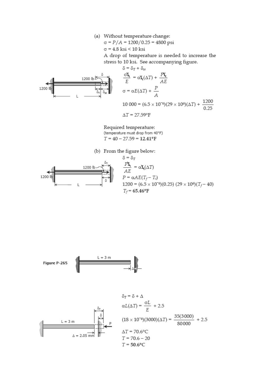
Problem 264
A steel rod 3 feet long with a cross-sectional area of 0.25 in.
2
is stretched between two
fixed points. The tensile force is 1200 lb at 40°F. Using E = 29 × 10
6
psi and α = 6.5 ×
10
-6
in./(in.·°F), calculate (a) the temperature at which the stress in the bar will be 10
ksi; and (b) the temperature at which the stress will be
zero.
Solution 264
Problem 265
A bronze bar 3 m long with a cross sectional area of 320 mm
2
is placed between two
rigid walls as shown in Fig. P-265. At a temperature of -20°C, the gap Δ = 25 mm. Find
the temperature at which the compressive stress in the bar will be 35 MPa. Use α =
18.0 × 10
-6
m/(m·°C) and E = 80 GPa.
Solution 265
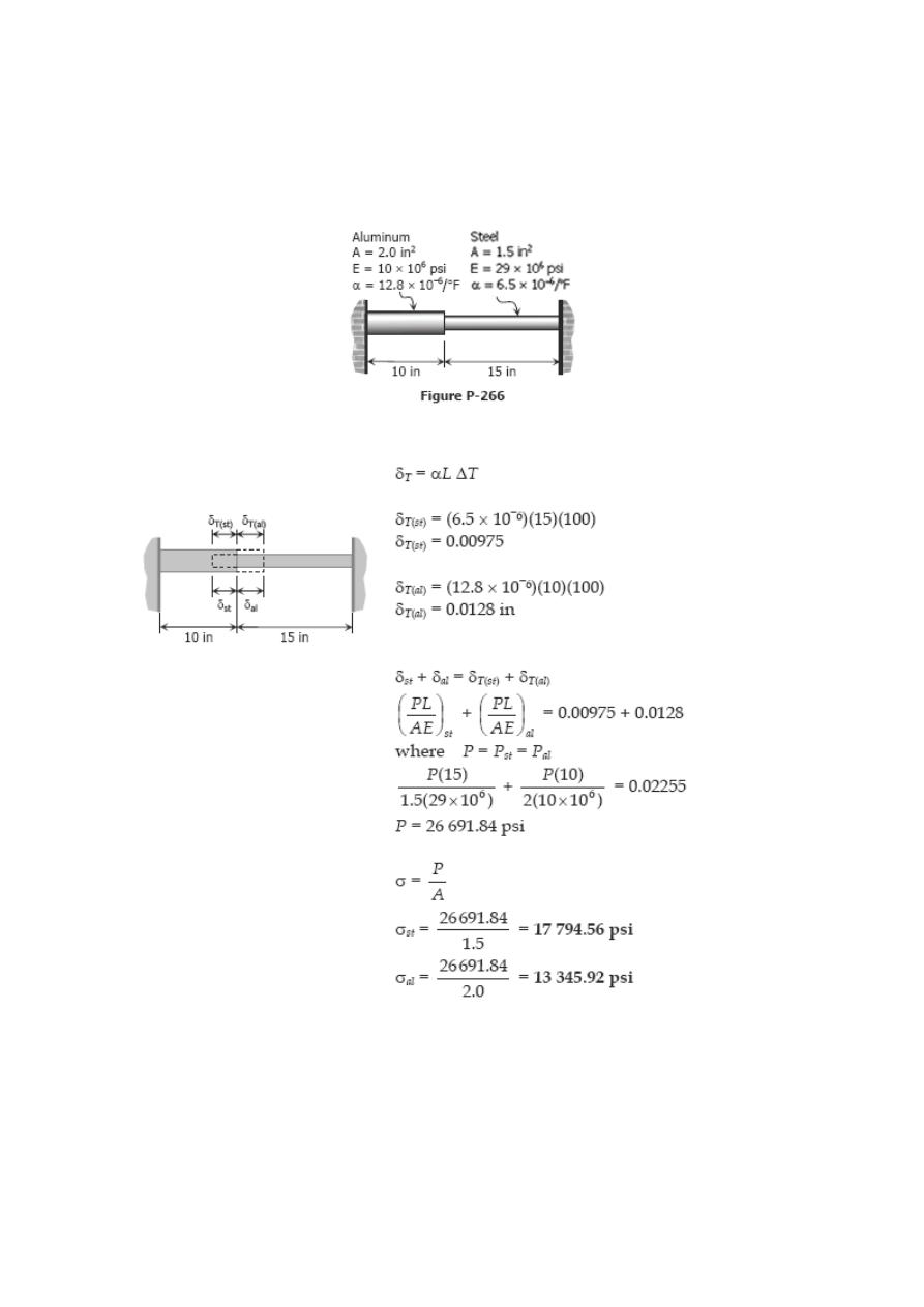
Problem 266
Calculate the increase in stress for each segment of the compound bar shown in Fig. P-
266 if the temperature increases by 100°F. Assume that the supports are unyielding
and that the bar is suitably braced against buckling.
Solution 266
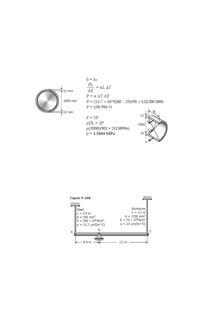
Problem 267
At a temperature of 80°C, a steel tire 12 mm thick and 90 mm wide that is to be shrunk
onto a locomotive driving wheel 2 m in diameter just fits over the wheel, which is at a
temperature of 25°C. Determine the contact pressure between the tire and wheel after
the assembly cools to 25°C. Neglect the deformation of the wheel caused by the
pressure of the tire. Assume α = 11.7 µm/(m·°C) and E = 200 GPa.
Solution 267
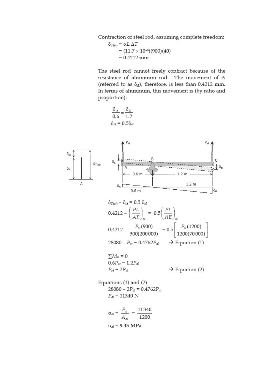
Problem 268
The rigid bar ABC in Fig. P-268 is pinned at B and attached to the two vertical rods.
Initially, the bar is horizontal and the vertical rods are stress-free. Determine the stress
in the aluminum rod if the temperature of the steel rod is decreased by 40°C. Neglect
the weight of bar ABC.
Solution 268
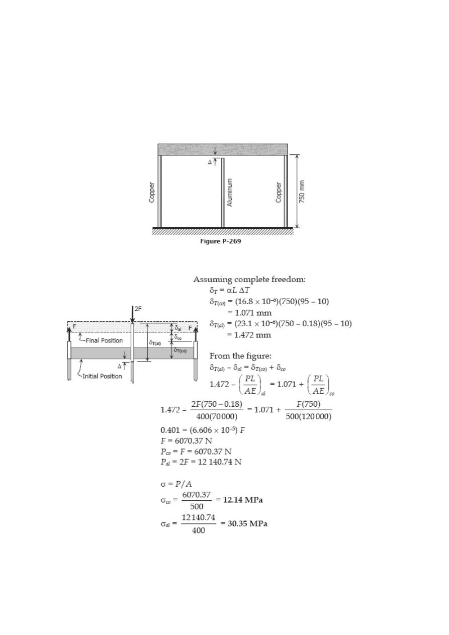
Problem 269
As shown in Fig. P-269, there is a gap between the aluminum bar and the rigid slab that
is supported by two copper bars. At 10°C, Δ = 0.18 mm. Neglecting the mass of the
slab, calculate the stress in each rod when the temperature in the assembly is increased
to 95°C. For each copper bar, A= 500 mm
2
, E = 120 GPa, and α = 16.8 µm/(m·°C). For
the aluminum bar, A = 400 mm
2
, E = 70 GPa, and α = 23.1 µm/(m·°C).
Solution 269
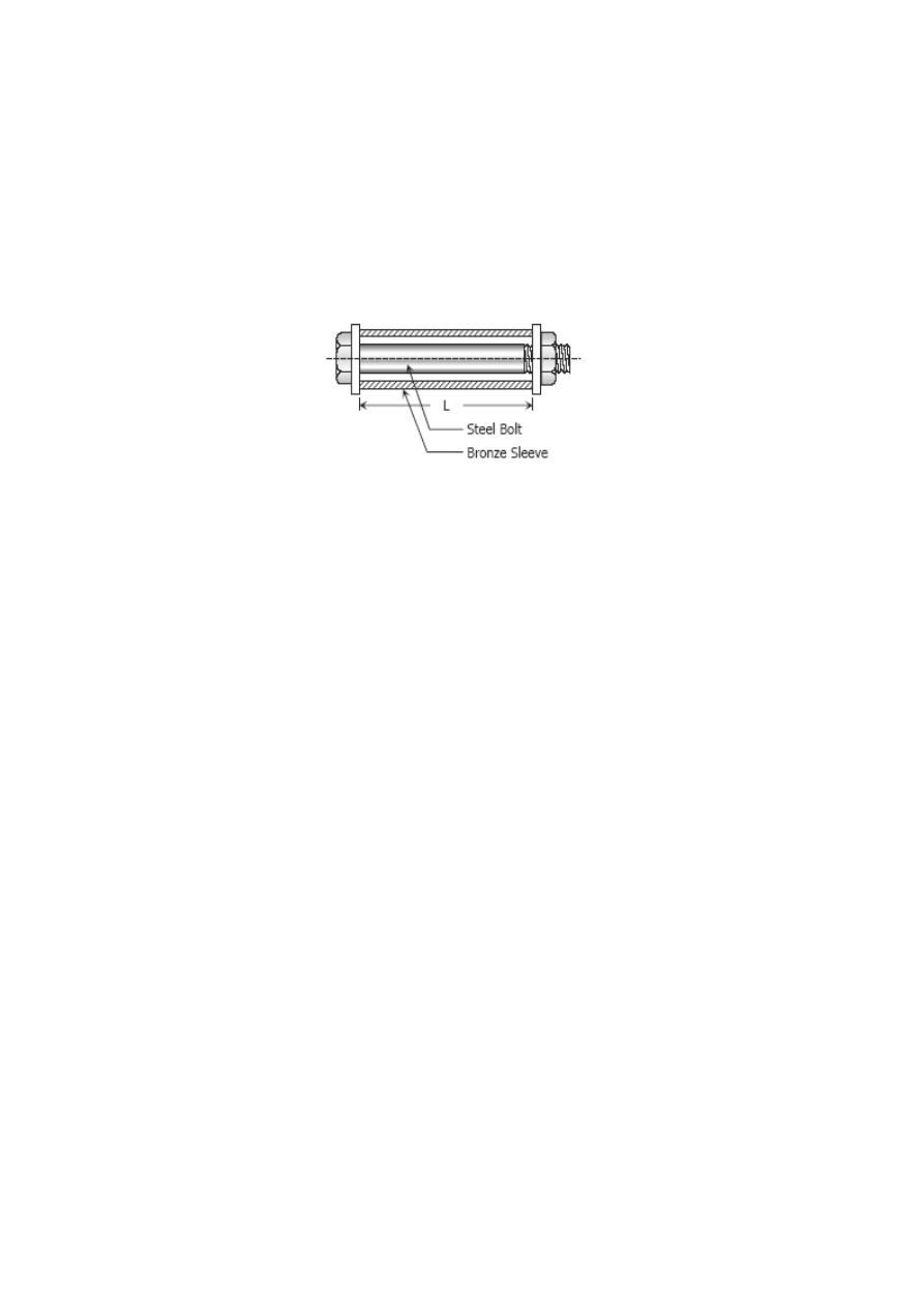
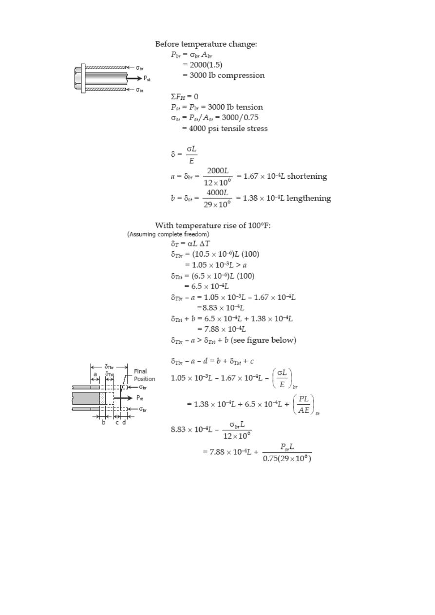
Problem 270
A bronze sleeve is slipped over a steel bolt and held in place by a nut that is turned to
produce an initial stress of 2000 psi in the bronze. For the steel bolt, A = 0.75 in
2
, E =
29 × 10
6
psi, and α = 6.5 × 10
–6
in/(in·°F). For the bronze sleeve, A = 1.5 in
2
, E = 12 ×
10
6
psi and α = 10.5 × 10
–6
in/(in·°F). After a temperature rise of 100°F, find the final
stress in each material.
Solution 270
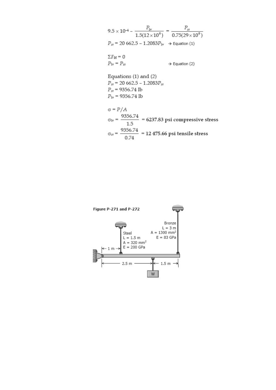
Problem 271
A rigid bar of negligible weight is supported as shown in Fig. P-271. If W = 80 kN,
compute the temperature change that will cause the stress in the steel rod to be 55
MPa. Assume the coefficients of linear expansion are 11.7 µm/(m·°C) for steel and 18.9
µm / (m·°C) for bronze.
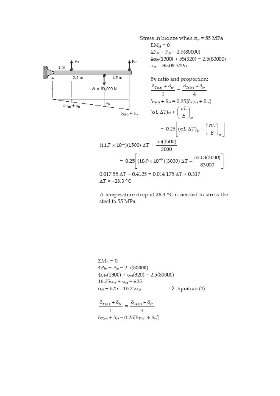
Solution 271
Problem 272
For the assembly in Fig. 271, find the stress in each rod if the temperature rises 30°C
after a load W = 120 kN is applied.
Solution 272
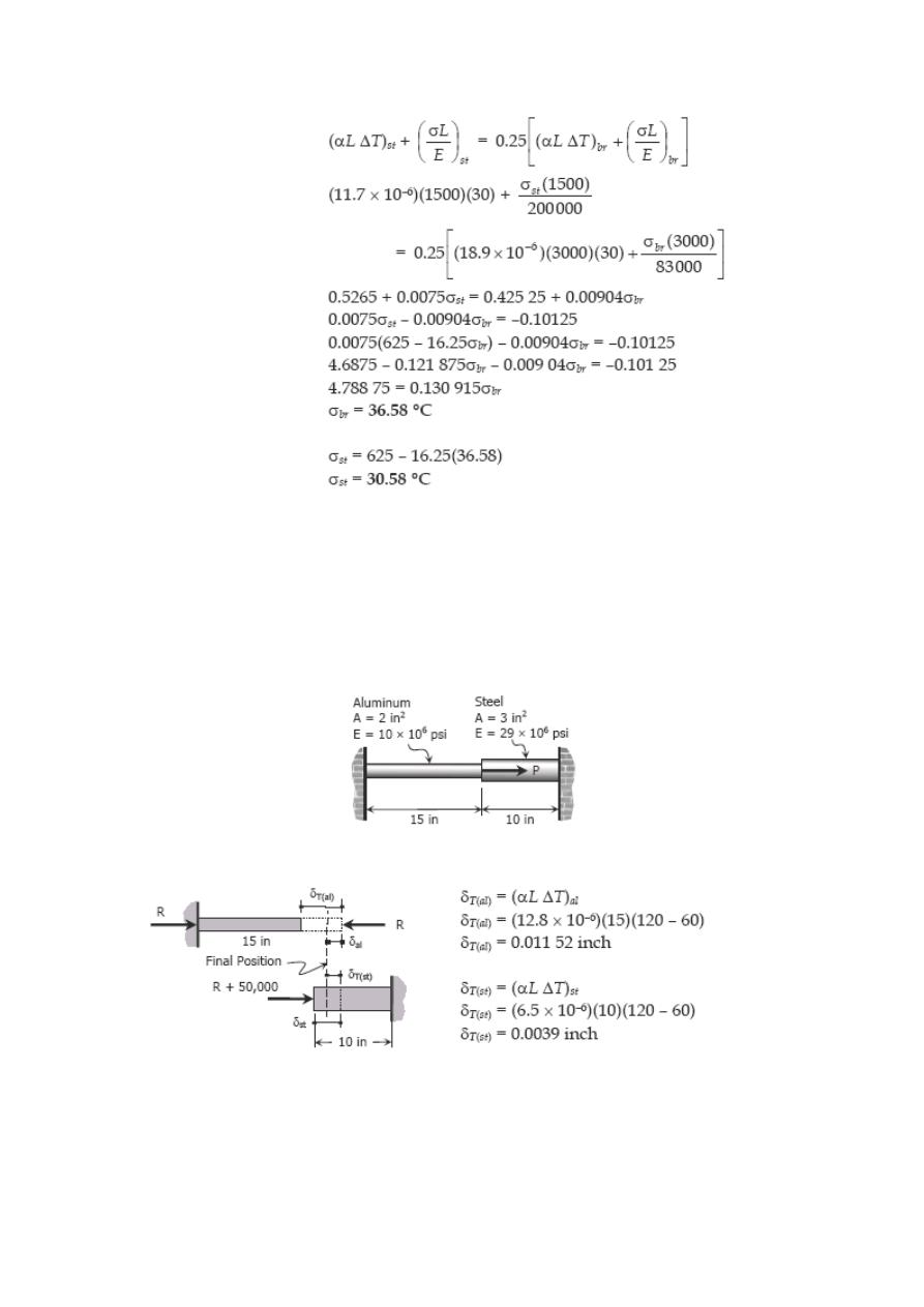
Problem 273
The composite bar shown in Fig. P-273 is firmly attached to unyielding supports. An
axial force P = 50 kips is applied at 60°F. Compute the stress in each material at 120°F.
Assume α = 6.5 × 10
–6
in/(in·°F) for steel and 12.8 × 10
–6
in/(in·°F) for aluminum.
Figure P-273 and P-274
Solution 273
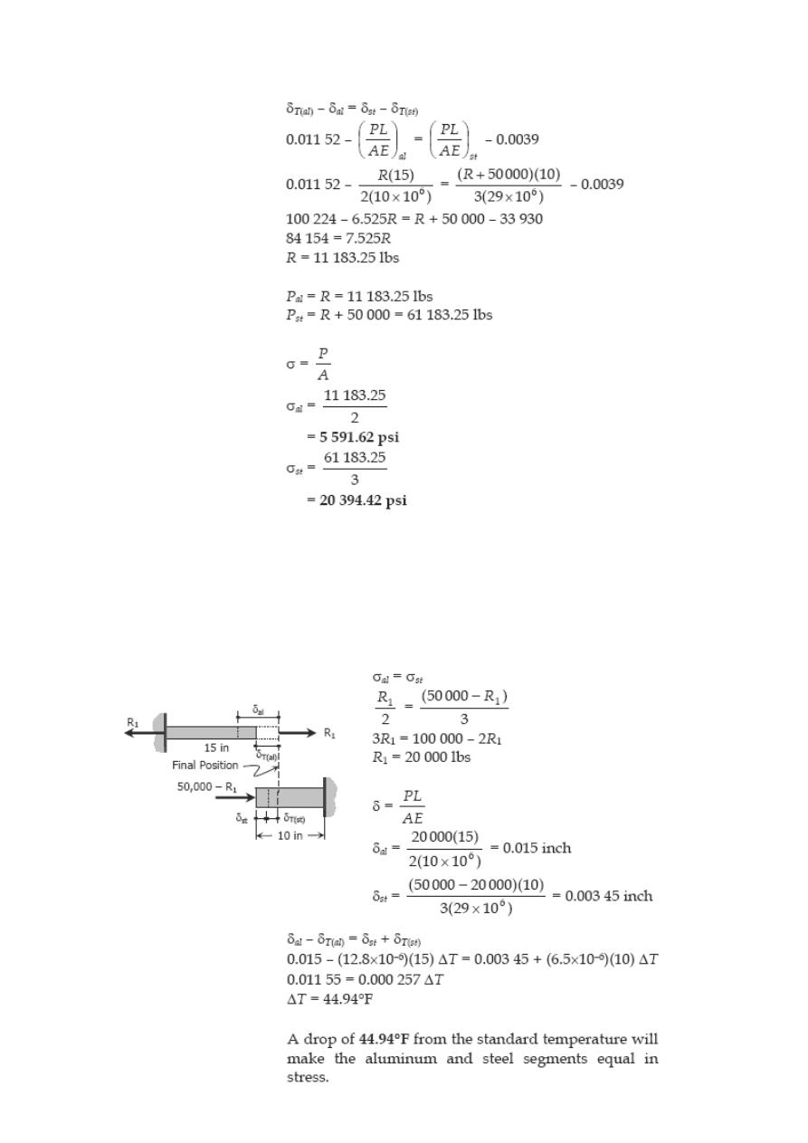
Problem 274
At what temperature will the aluminum and steel segments in Prob. 273 have
numerically equal stress?
Solution 274
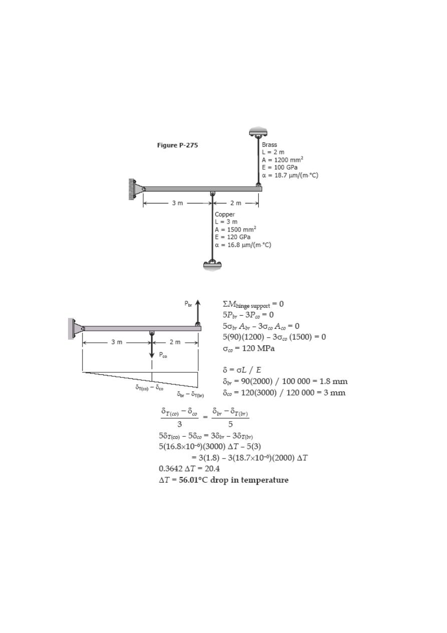
Problem 275
A rigid horizontal bar of negligible mass is connected to two rods as shown in Fig. P-
275. If the system is initially stress-free. Calculate the temperature change that will
cause a tensile stress of 90 MPa in the brass rod. Assume that both rods are subjected
to the change in temperature.
Solution 275
Problem 276
Four steel bars jointly support a mass of 15 Mg as shown in Fig. P-276. Each bar has a
cross-sectional area of 600 mm2. Find the load carried by each bar after a temperature
rise of 50°C. Assume α = 11.7 µm/(m·°C) and E = 200 GPa.
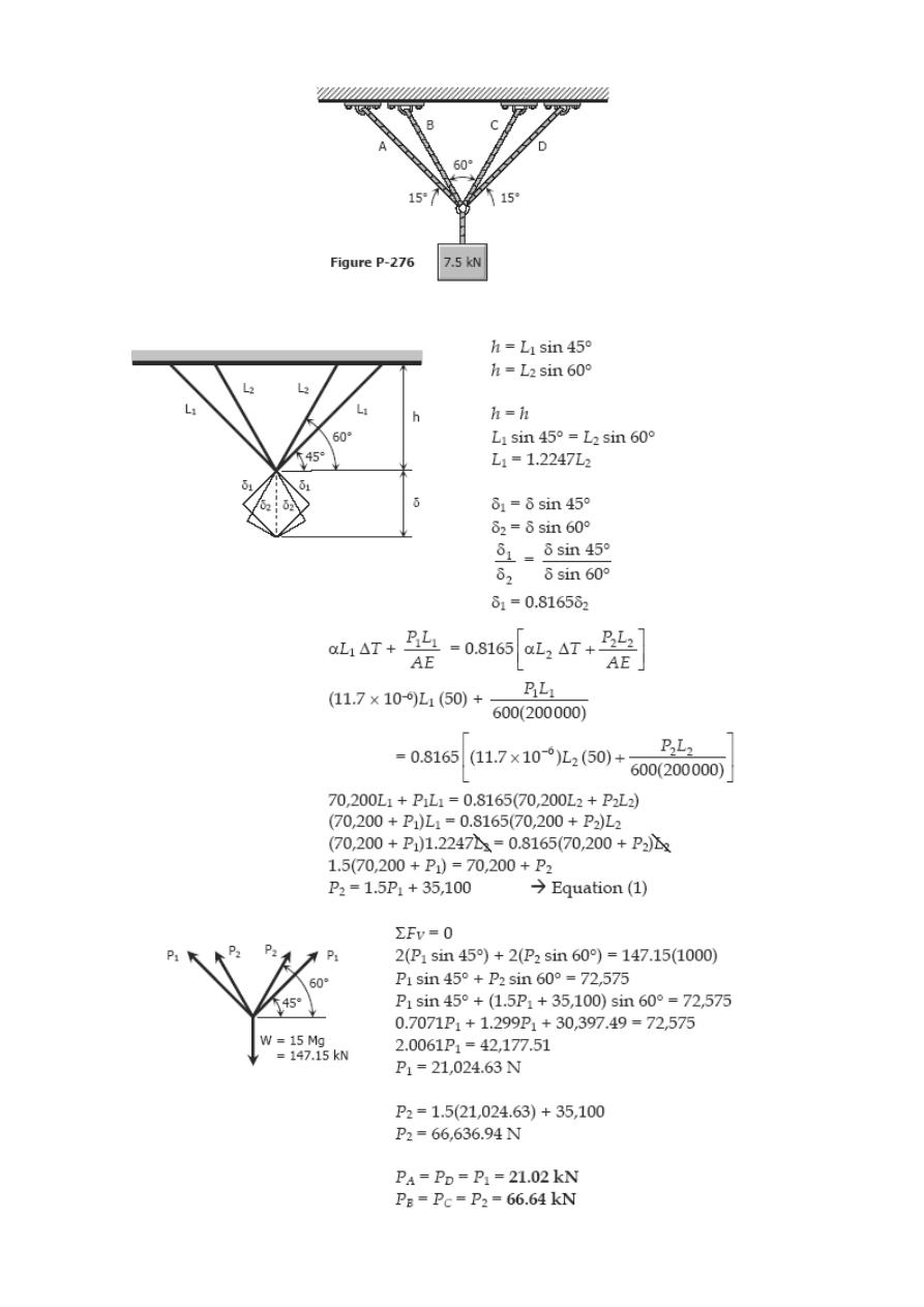
Solution 276
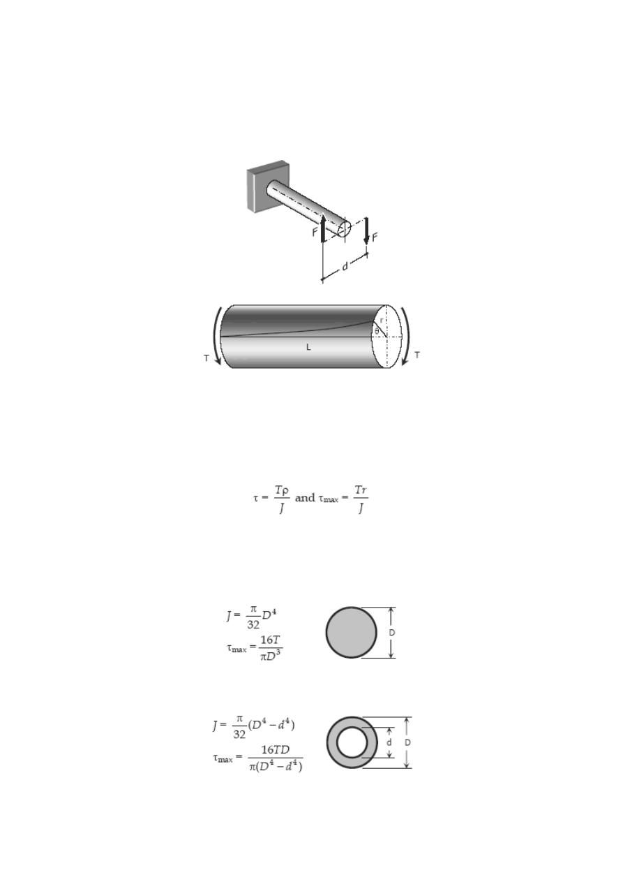
Torsion
Consider a bar to be rigidly attached at one end and twisted at the other end by a
torque or twisting moment T equivalent to F × d, which is applied perpendicular to the
axis of the bar, as shown in the figure. Such a bar is said to be in torsion.
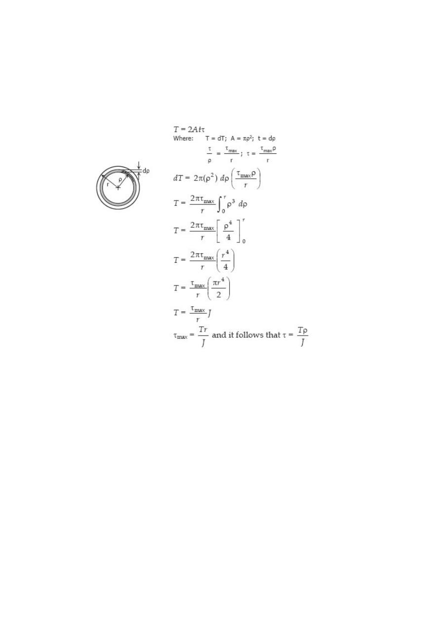
TORSIONAL SHEARING STRESS, τ
For a solid or hollow circular shaft subject to a twisting moment T, the torsional
shearing stress τ at a distance ρ from the center of the shaft is
where J is the polar moment of inertia of the section and r is the outer radius.
For solid cylindrical shaft:
For hollow cylindrical shaft:
ANGLE OF TWIST
The angle θ through which the bar length L will twist is
where T is the torque in N·mm, L is the length of shaft in mm, G is shear modulus in
MPa, J is the polar moment of inertia in mm
4
, D and d are diameter in mm, and r is the
radius in mm.
POWER TRANSMITTED BY THE SHAFT
A shaft rotating with a constant angular velocity ω (in radians per second) is being acted
by a twisting moment T. The power transmitted by the shaft is
where T is the torque in N·m, f is the number of revolutions per second, and P is the
power in watts.
Solved Problems in Torsion
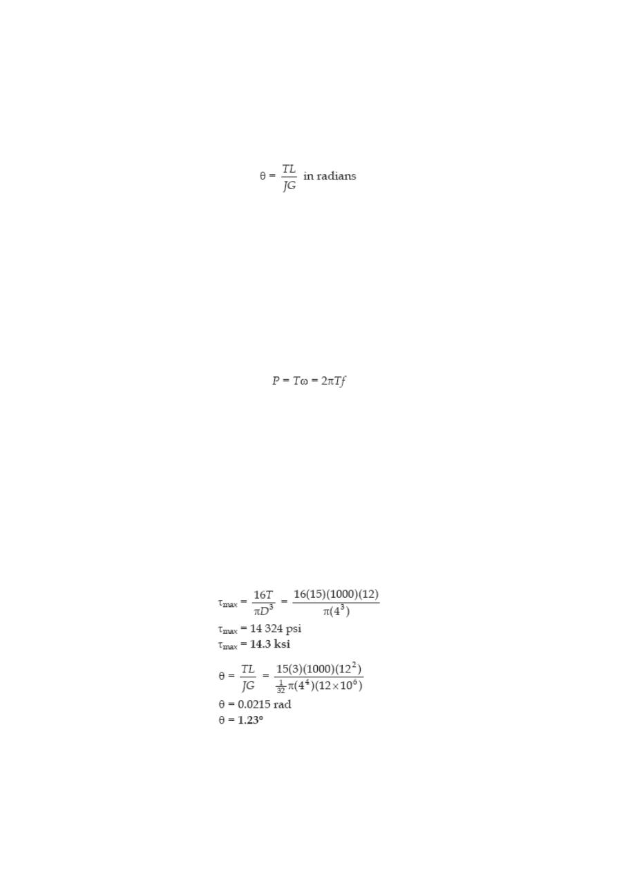
Problem 304
A steel shaft 3 ft long that has a diameter of 4 in. is subjected to a torque of 15 kip·ft.
Determine the maximum shearing stress and the angle of twist. Use G = 12 × 10
6
psi.
Solution 304
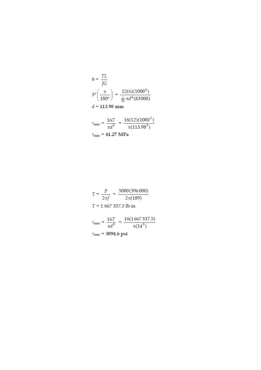
Problem 305
What is the minimum diameter of a solid steel shaft that will not twist through more
than 3° in a 6-m length when subjected to a torque of 12 kN·m? What maximum
shearing stress is developed? Use G = 83 GPa.
Solution 305
Problem 306
A steel marine propeller shaft 14 in. in diameter and 18 ft long is used to transmit 5000
hp at 189 rpm. If G = 12 × 10
6
psi, determine the maximum shearing stress.
Solution 306
Problem 307
A solid steel shaft 5 m long is stressed at 80 MPa when twisted through 4°. Using G =
83 GPa, compute the shaft diameter. What power can be transmitted by the shaft at 20
Hz?
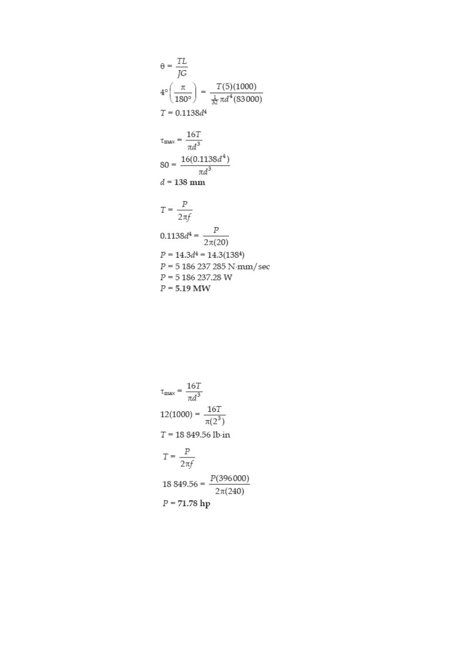
Solution 307
Problem 308
A 2-in-diameter steel shaft rotates at 240 rpm. If the shearing stress is limited to 12
ksi, determine the maximum horsepower that can be transmitted.
Solution 308
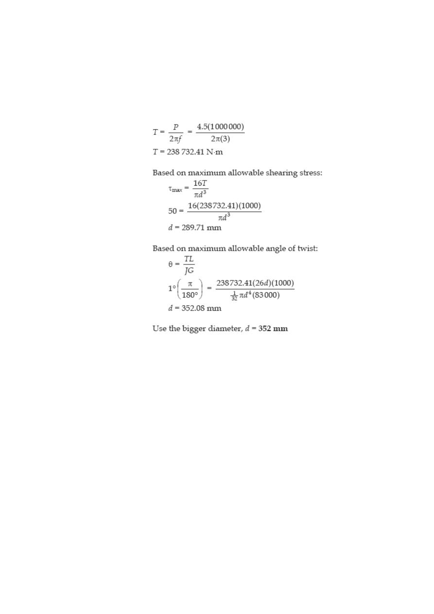
Problem 309
A steel propeller shaft is to transmit 4.5 MW at 3 Hz without exceeding a shearing stress
of 50 MPa or twisting through more than 1° in a length of 26 diameters. Compute the
proper diameter if G = 83 GPa.
Solution 309
Problem 310
Show that the hollow circular shaft whose inner diameter is half the outer diameter has
a torsional strength equal to 15/16 of that of a solid shaft of the same outside diameter.
Solution 310
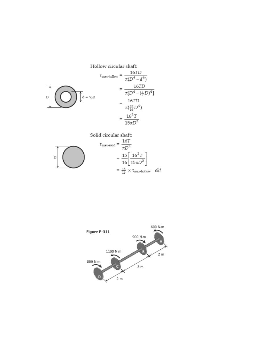
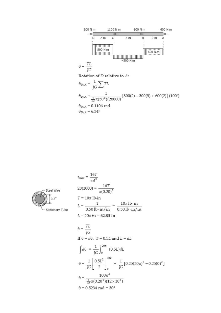
Problem 311
An aluminum shaft with a constant diameter of 50 mm is loaded by torques applied to
gears attached to it as shown in Fig. P-311. Using G = 28 GPa, determine the relative
angle of twist of gear D relative to gear A.
Solution 311
Problem 312
A flexible shaft consists of a 0.20-in-diameter steel wire encased in a stationary tube
that fits closely enough to impose a frictional torque of 0.50 lb·in/in. Determine the
maximum length of the shaft if the shearing stress is not to exceed 20 ksi. What will be
the angular deformation of one end relative to the other end? G = 12 × 10
6
psi.
Solution 312
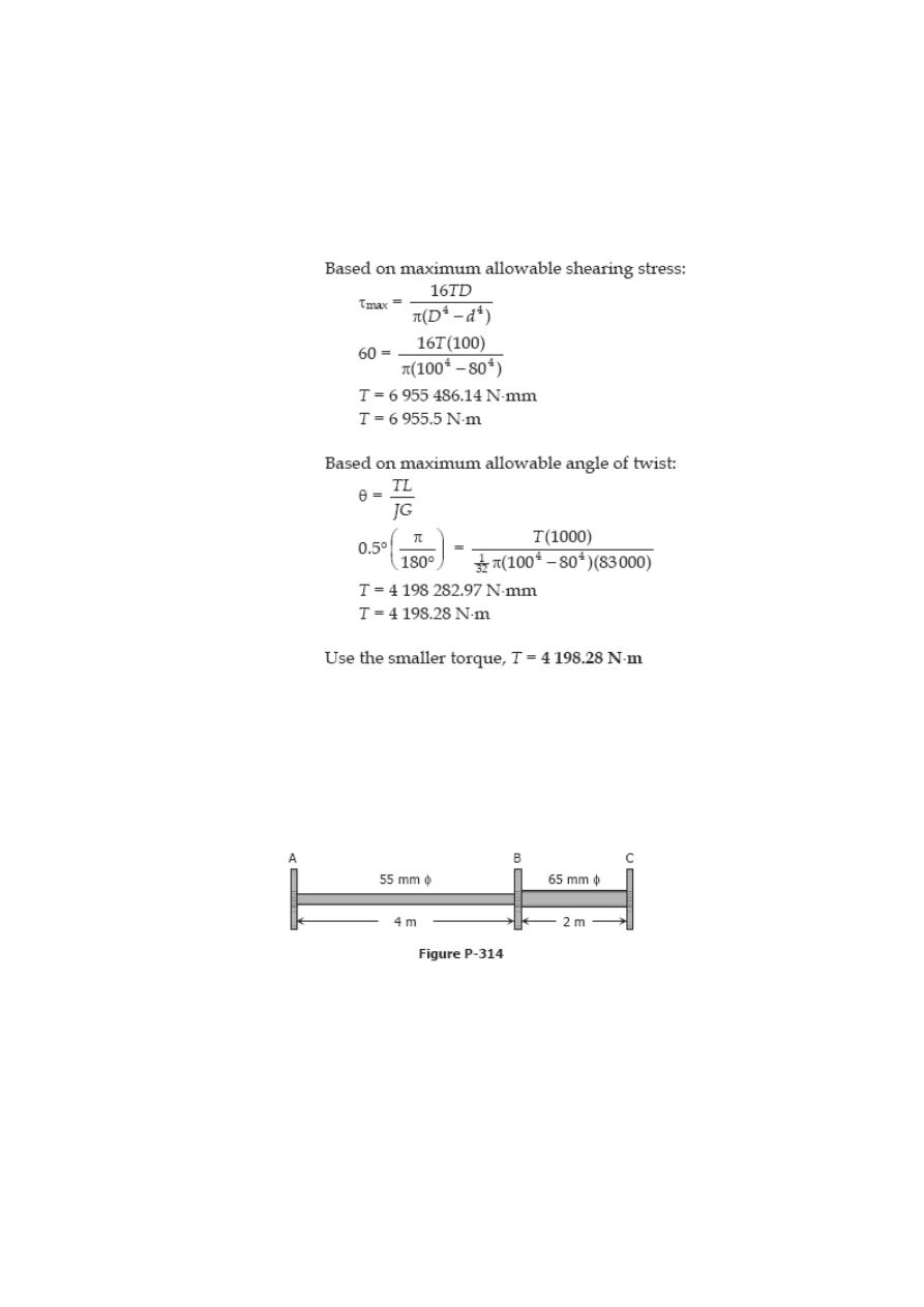
Problem 313
Determine the maximum torque that can be applied to a hollow circular steel shaft of
100-mm outside diameter and an 80-mm inside diameter without exceeding a shearing
stress of 60 MPa or a twist of 0.5 deg/m. Use G = 83 GPa.
Solution 313
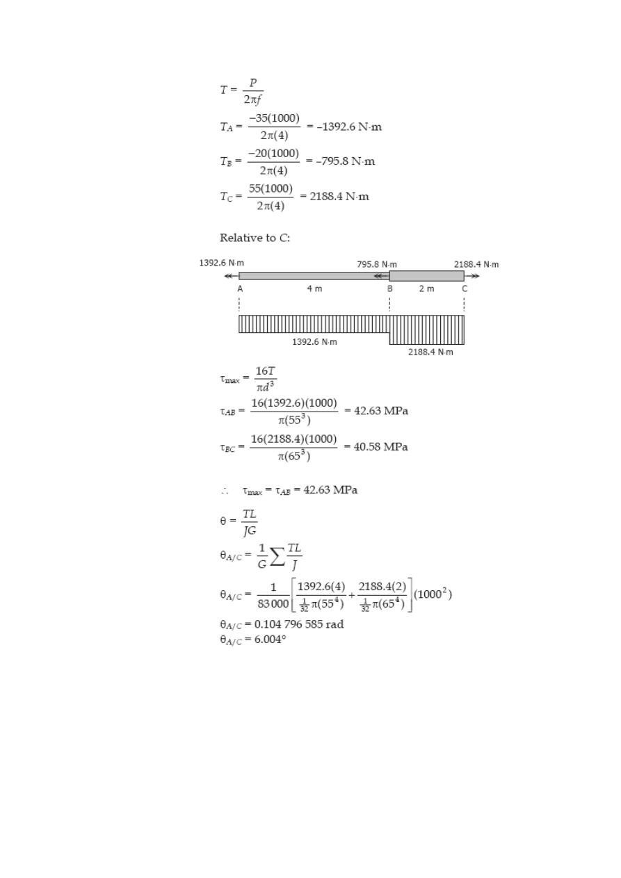
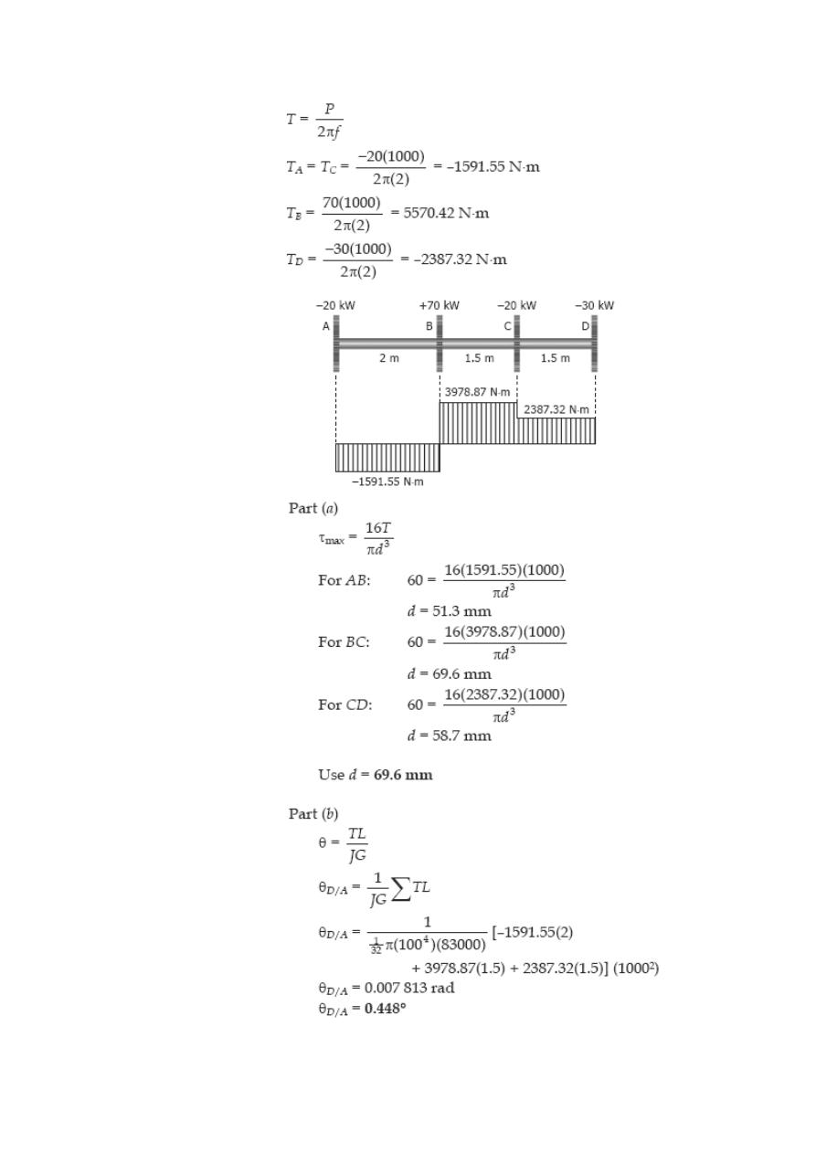
Problem 314
The steel shaft shown in Fig. P-314 rotates at 4 Hz with 35 kW taken off at A, 20 kW
removed at B, and 55 kW applied at C. Using G = 83 GPa, find the maximum shearing
stress and the angle of rotation of gear A relative to gear C.
Solution 314
Problem 315
A 5-m steel shaft rotating at 2 Hz has 70 kW applied at a gear that is 2 m from the left
end where 20 kW are removed. At the right end, 30 kW are removed and another 20
kW leaves the shaft at 1.5 m from the right end. (a) Find the uniform shaft diameter so
that the shearing stress will not exceed 60 MPa. (b) If a uniform shaft diameter of 100
mm is specified, determine the angle by which one end of the shaft lags behind the
other end. Use G = 83 GPa.
Solution 315
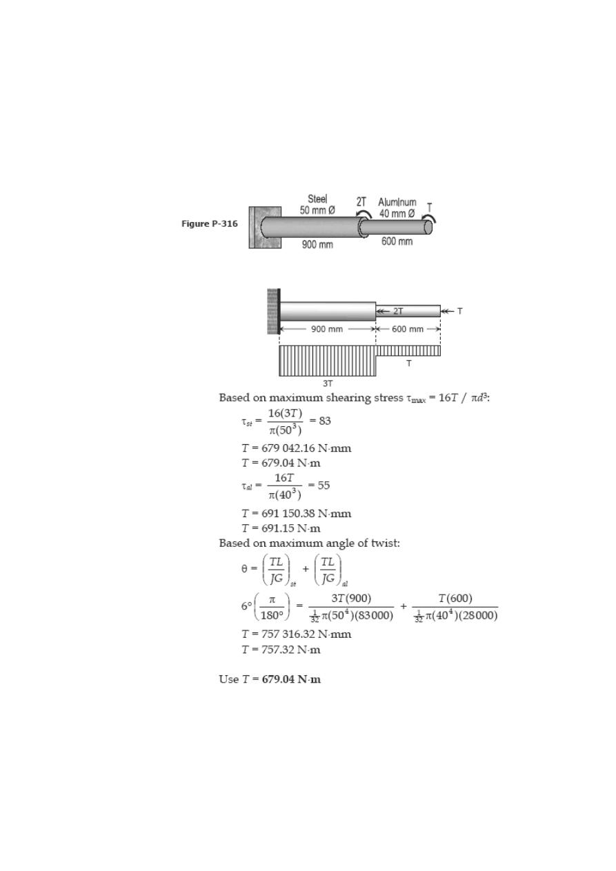
Problem 316
A compound shaft consisting of a steel segment and an aluminum segment is acted
upon by two torques as shown in Fig. P-316. Determine the maximum permissible value
of T subject to the following conditions: τ
st
= 83 MPa, τ
al
= 55 MPa, and the angle of
rotation of the free end is limited to 6°. For steel, G = 83 GPa and for aluminum, G =
28 GPa.
Solution 316
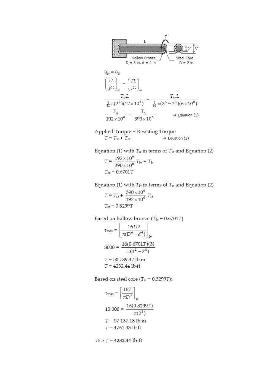
Problem 317
A hollow bronze shaft of 3 in. outer diameter and 2 in. inner diameter is slipped over a
solid steel shaft 2 in. in diameter and of the same length as the hollow shaft. The two
shafts are then fastened rigidly together at their ends. For bronze, G = 6 × 10
6
psi, and
for steel, G = 12 × 10
6
psi. What torque can be applied to the composite shaft without
exceeding a shearing stress of 8000 psi in the bronze or 12 ksi in the steel?
Solution 317
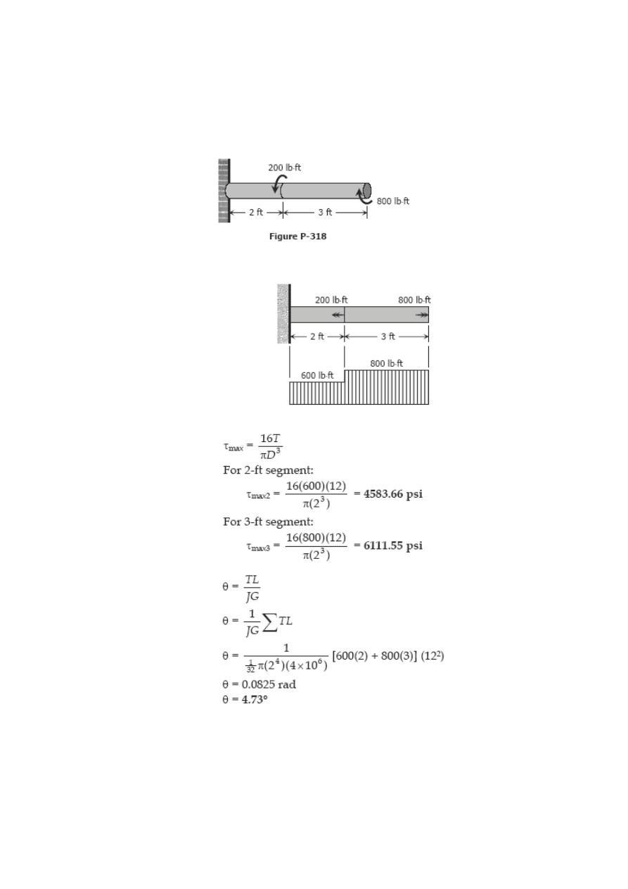
Problem 318
A solid aluminum shaft 2 in. in diameter is subjected to two torques as shown in Fig. P-
318. Determine the maximum shearing stress in each segment and the angle of rotation
of the free end. Use G = 4 × 10
6
psi.
Solution 318
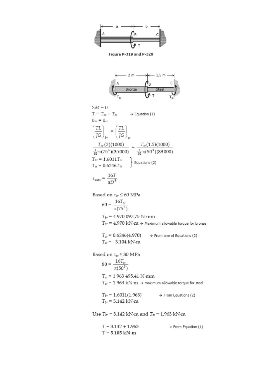
Problem 319
The compound shaft shown in Fig. P-319 is attached to rigid supports. For the bronze
segment AB, the diameter is 75 mm, τ ≤ 60 MPa, and G = 35 GPa. For the steel
segment BC, the diameter is 50 mm, τ ≤ 80 MPa, and G = 83 GPa. If a = 2 m and b =
1.5 m, compute the maximum torque T that can be applied.
Solution 319
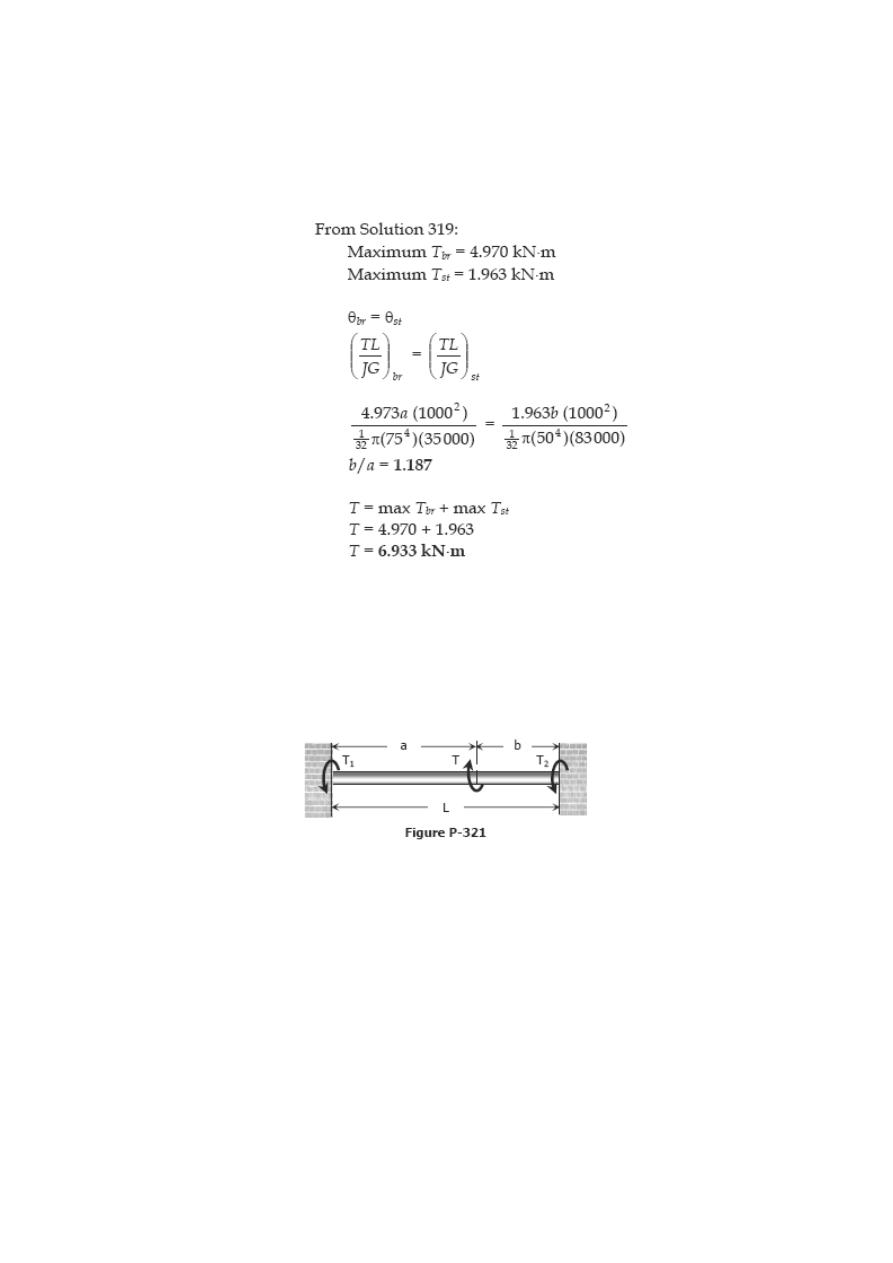
Problem 320
In Prob. 319, determine the ratio of lengths b/a so that each material will be stressed to
its permissible limit. What torque T is required?
Solution 320
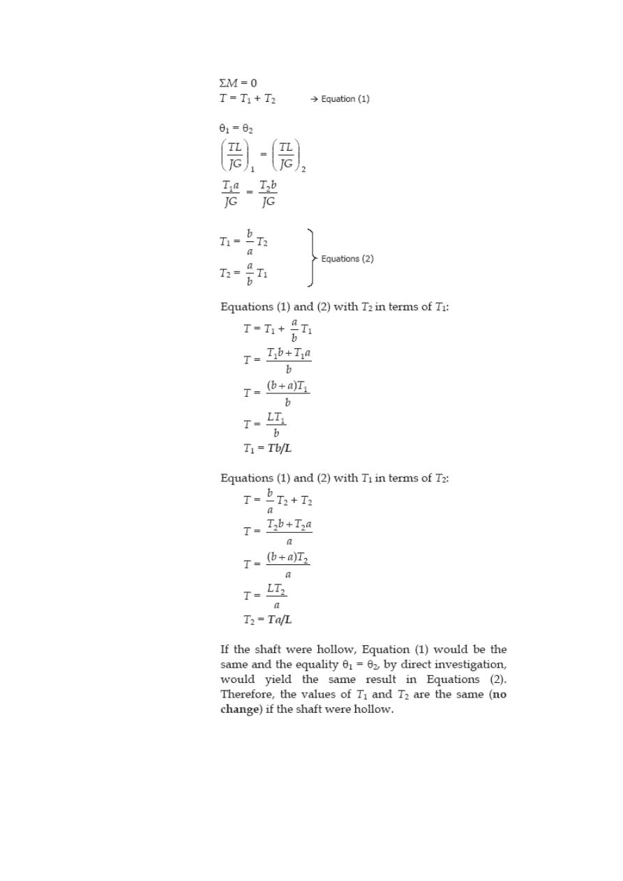
Problem 321
A torque T is applied, as shown in Fig. P-321, to a solid shaft with built-in ends. Prove
that the resisting torques at the walls are T
1
= Tb/L and T
2
= Ta/L. How would these
values be changed if the shaft were hollow?
Solution 321
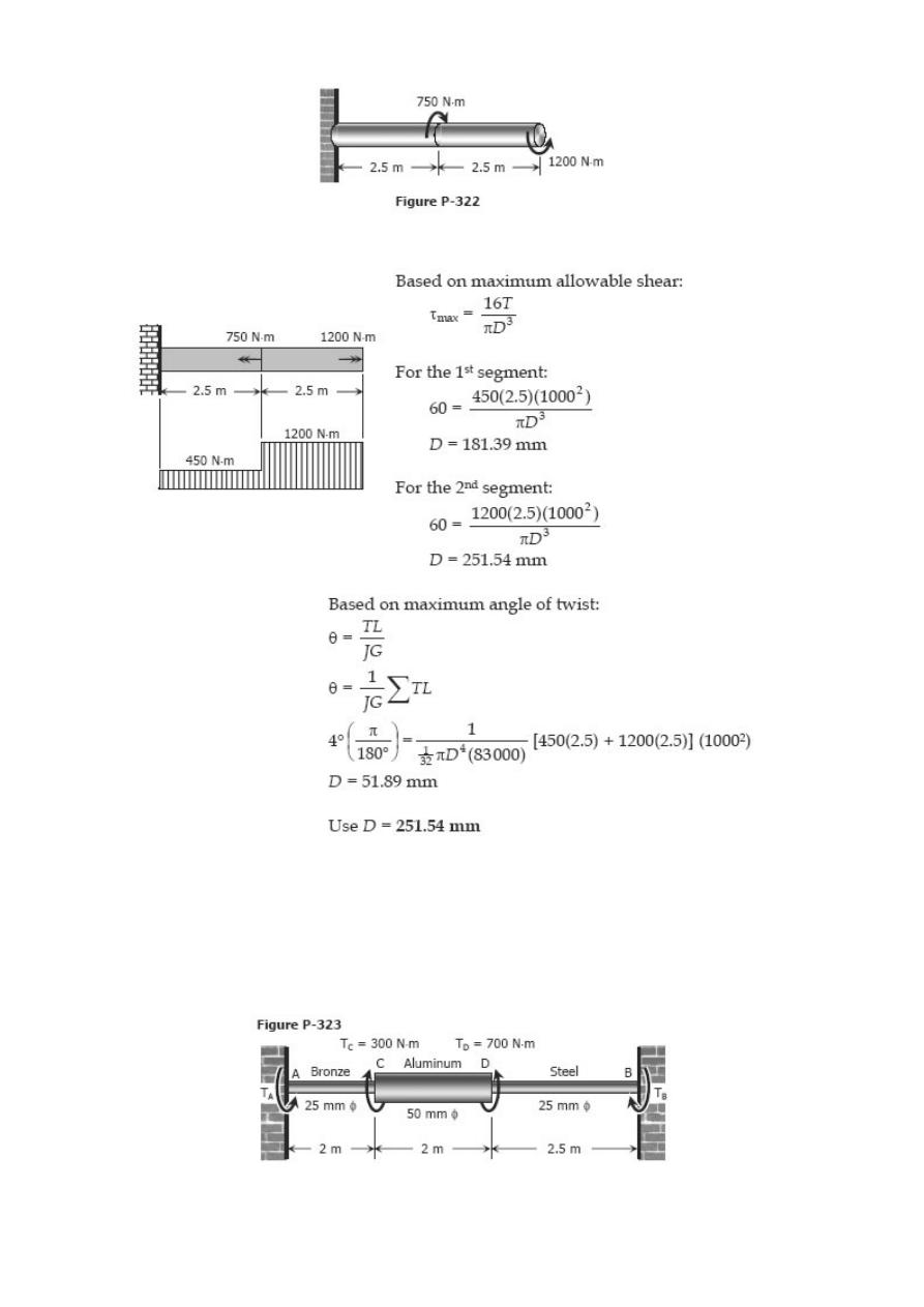
Problem 322
A solid steel shaft is loaded as shown in Fig. P-322. Using G = 83 GPa, determine the
required diameter of the shaft if the shearing stress is limited to 60 MPa and the angle
of rotation at the free end is not to exceed 4 deg.
Solution 322
Problem 323
A shaft composed of segments AC, CD, and DB is fastened to rigid supports and loaded
as shown in Fig. P-323. For bronze, G = 35 GPa; aluminum, G = 28 GPa, and for steel,
G = 83 GPa. Determine the maximum shearing stress developed in each segment.
Solution 323
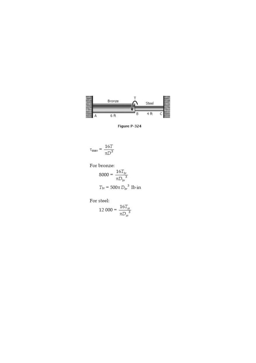
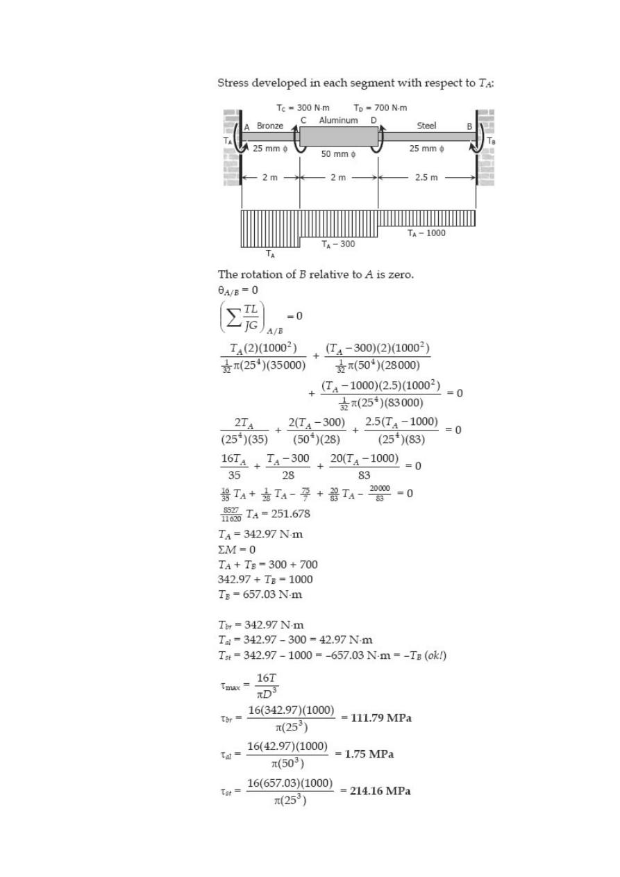
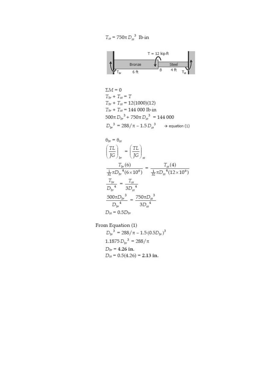
Problem 324
The compound shaft shown in Fig. P-324 is attached to rigid supports. For the bronze
segment AB, the maximum shearing stress is limited to 8000 psi and for the steel
segment BC, it is limited to 12 ksi. Determine the diameters of each segment so that
each material will be simultaneously stressed to its permissible limit when a torque T =
12 kip·ft is applied. For bronze, G = 6 × 10
6
psi and for steel, G = 12 × 10
6
psi.
Solution 324
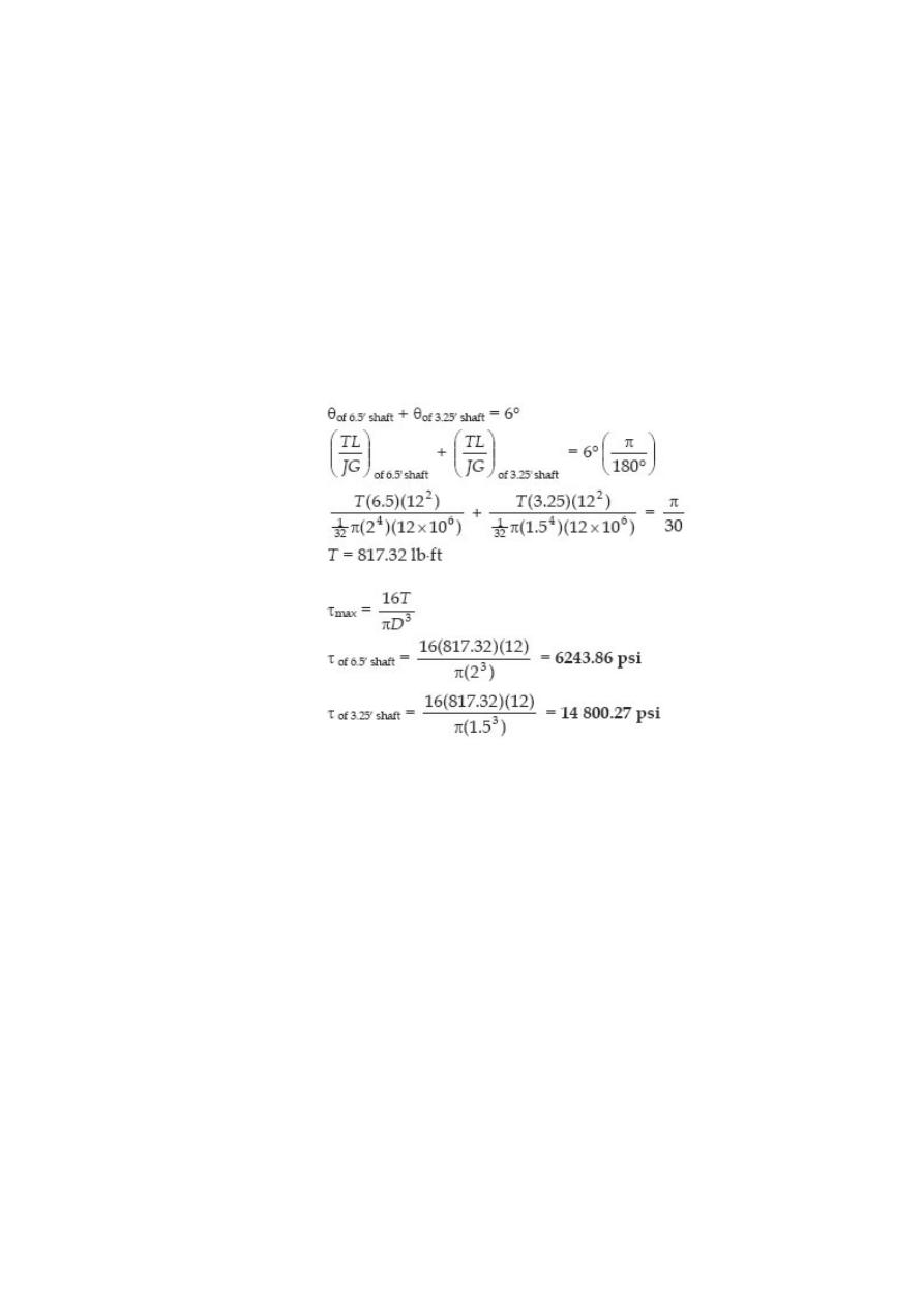
Problem 325
The two steel shaft shown in Fig. P-325, each with one end built into a rigid support
have flanges rigidly attached to their free ends. The shafts are to be bolted together at
their flanges. However, initially there is a 6° mismatch in the location of the bolt holes
as shown in the figure. Determine the maximum shearing stress in each shaft after the
shafts are bolted together. Use G = 12 × 10
6
psi and neglect deformations of the bolts
and
flanges.
Solution 325
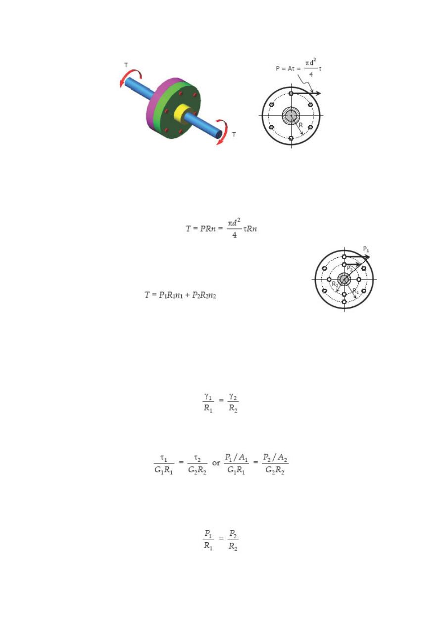
Flanged Bolt Couplings
In shaft connection called flanged bolt couplings (see figure above), the torque is
transmitted by the shearing force P created in he bolts that is assumed to be uniformly
distributed. For any number of bolts n, the torque capacity of the coupling is
If a coupling has two concentric rows of bolts, the torque capacity
is
where the subscript 1 refer to bolts on the outer circle an
subscript 2 refer to bolts on the inner circle. See figure.
For rigid flanges, the shear deformations in the bolts are proportional to their radial
distances from the shaft axis. The shearing strains are related by
Using Hooke’s law for shear, G = τ / γ, we have
If the bolts on the two circles have the same area, A
1
= A
2
, and if the bolts are made of
the same material, G
1
= G
2
, the relation between P
1
and P
2
reduces to
Solved Problems in Flanged Bolt Couplings
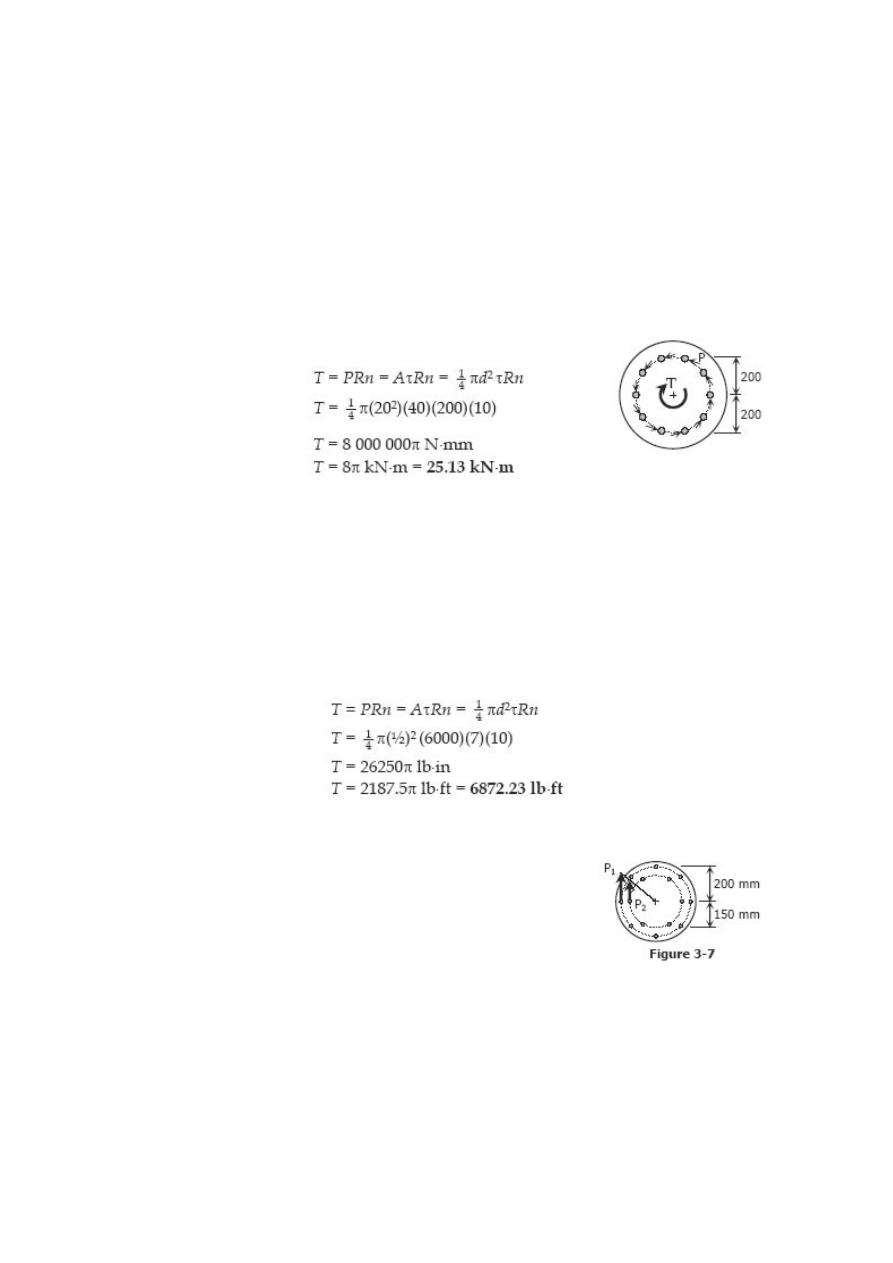
Problem 326
A flanged bolt coupling consists of ten 20-mmdiameter bolts spaced evenly around a
bolt circle 400 mm in diameter. Determine the torque capacity of the coupling if the
allowable shearing stress in the bolts is 40 MPa.
Solution 326
Problem 327
A flanged bolt coupling consists of ten steel ½ -in.-diameter bolts spaced evenly around
a bolt circle 14 in. in diameter. Determine the torque capacity of the coupling if the
allowable shearing stress in the bolts is 6000 psi.
Solution 327
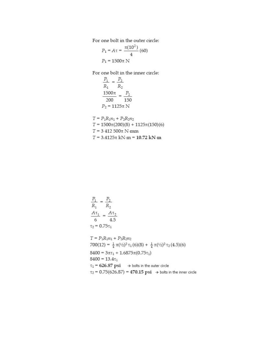
Problem 328
A flanged bolt coupling consists of eight 10-mmdiameter steel
bolts on a bolt circle 400 mm in diameter, and six 10-mm-
diameter steel bolts on a concentric bolt circle 300 mm in
diameter, as shown in Fig. 3-7. What torque can be applied
without exceeding a shearing stress of 60 MPa in the bolts?
Solution 328
Problem 329
A torque of 700 lb-ft is to be carried by a flanged bolt coupling that consists of eight ½ -
in.-diameter steel bolts on a circle of diameter 12 in. and six ½ -in.-diameter steel bolts
on a circle of diameter 9 in. Determine the shearing stress in the bolts.
Solution 329
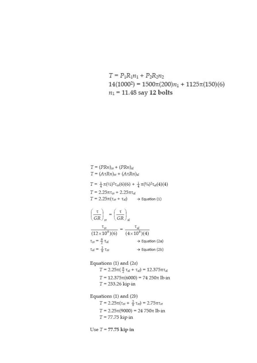
Problem 330
Determine the number of 10-mm-diameter steel bolts that must be used on the 400-
mm bolt circle of the coupling described in Prob. 328 to increase the torque capacity to
14 kN·m
Solution 330
Problem 331
A flanged bolt coupling consists of six ½ -in. steel bolts evenly spaced around a bolt
circle 12 in. in diameter, and four ¾ -in. aluminum bolts on a concentric bolt circle 8 in.
in diameter. What torque can be applied without exceeding 9000 psi in the steel or
6000 psi in the aluminum? Assume G
st
= 12 × 10
6
psi and G
al
= 4 × 10
6
psi.
Solution 331
Problem 332
In a rivet group subjected to a twisting couple T, show that the torsion formula τ = Tρ/J
can be used to find the shearing stress t at the center of any rivet. Let J = ΣAρ
2
, where
A is the area of a rivet at the radial distance ρ from the centroid of the rivet group.
Solution 332
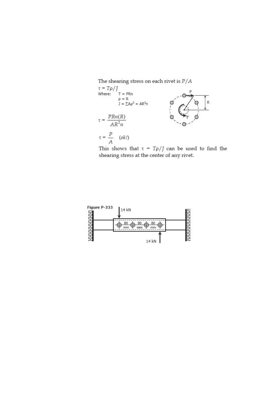
Problem 333
A plate is fastened to a fixed member by four 20-mm diameter rivets arranged as
shown in Fig. P-333. Compute the maximum and minimum shearing stress developed.

Solution 333
Problem 334
Six 7/8-in-diameter rivets fasten the plate in Fig. P-334 to the fixed member. Using the
results of Prob. 332, determine the average shearing stress caused in each rivet by the
14 kip loads. What additional loads P can be applied before the shearing stress in any
rivet exceeds 8000 psi?

Solution 334
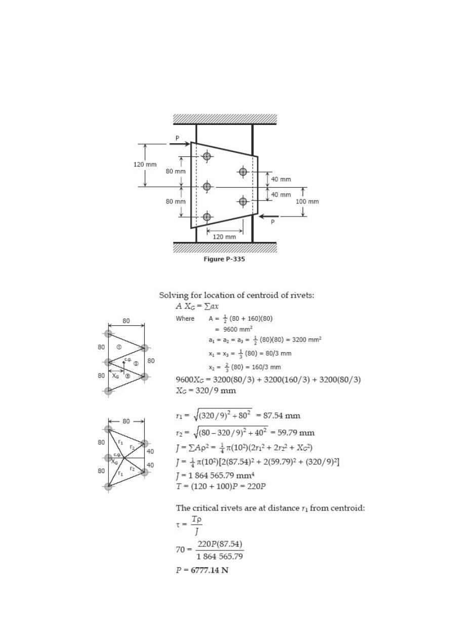
Problem 335
The plate shown in Fig. P-335 is fastened to the fixed member by five 10-mm-diameter
rivets. Compute the value of the loads P so that the average shearing stress in any rivet
does not exceed 70 MPa. (Hint: Use the results of Prob. 332.)
Solution 335
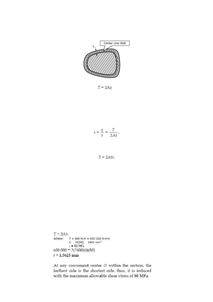
Torsion of Thin-Walled Tubes
The torque applied to thin-walled tubes is expressed as
where T is the torque in N·mm, A is the area enclosed by the centerline of the tube (as
shown in the stripefilled portion) in mm
2
, and q is the shear flow in N/mm.
The average shearing stress across any thickness t is
Thus, torque T ca also be expressed as
Solved Problems in Torsion of Thin-Walled Tubes
Problem 337
A torque of 600 N·m is applied to the rectangular section shown in Fig. P-337.
Determine the wall thickness t so as not to exceed a shear stress of 80 MPa. What is the
shear stress in the short sides? Neglect stress concentration at the corners.
Solution 337
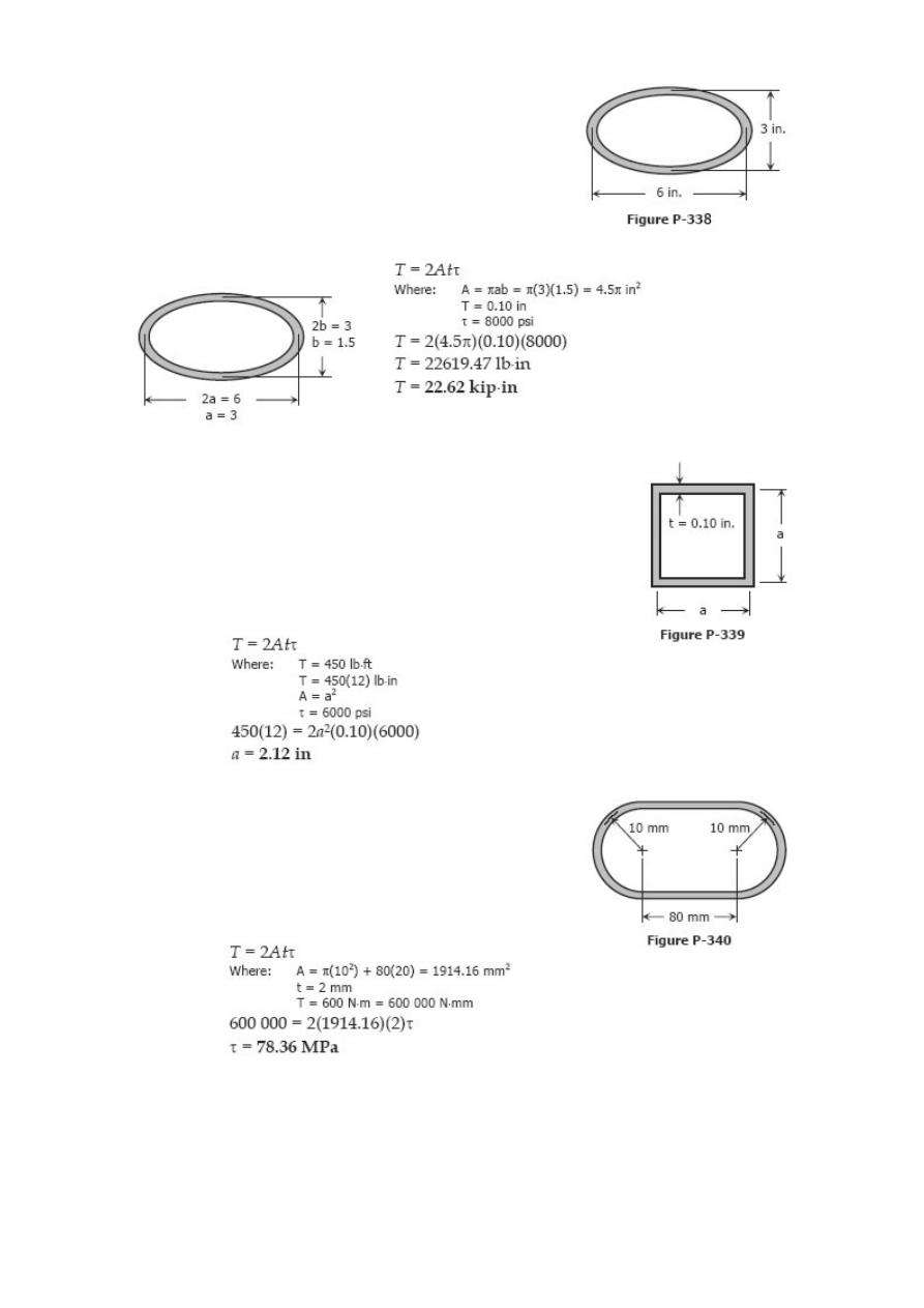
Problem 338
A tube 0.10 in. thick has an elliptical shape shown in Fig.
P-338. What torque will cause a shearing stress of 8000
psi?
Solution 338
Problem 339
A torque of 450 lb·ft is applied to the square section shown in Fi
P-339. Determine the smallest permissi
g.
ble dimension a if the
shearing stress is limited to 6000 psi.
Solution 339
Problem 340
A tube 2 mm thick has the shape shown in Fig. P-340. Find
the shearing stress caused by a torque of 600 N·m.
Solution 340
Problem 341
Derive the torsion formula τ = Tρ/J for a solid circular section by assuming the section is
composed of a series of concentric thin circular tubes. Assume that the shearing stress
at any point is proportional to its radial distance.
Solution 341
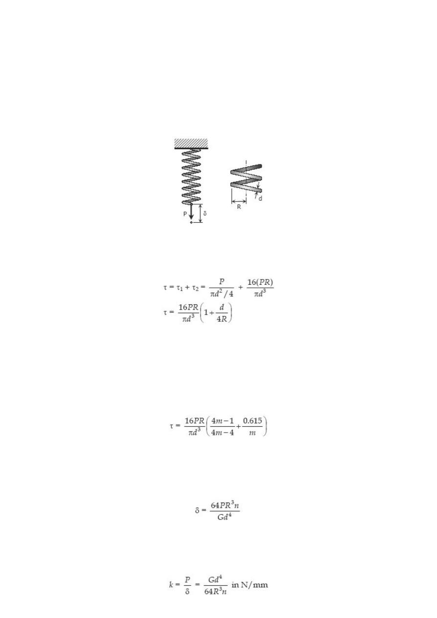
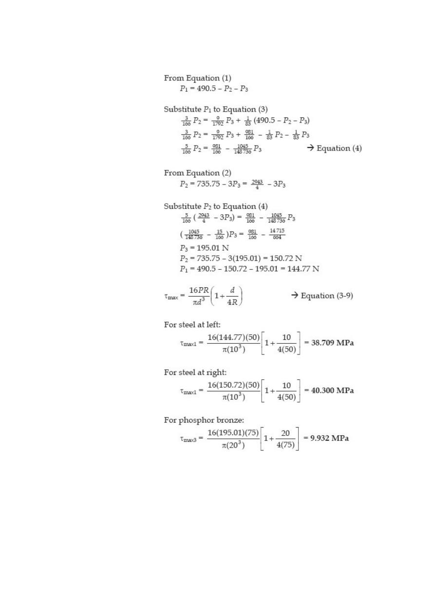
Helical Springs
When close-coiled helical spring, composed of a wire of round rod of diameter d wound
into a helix of mean radius R with n number of turns, is subjected to an axial load P
produces the following stresses and elongation:
The maximum shearing stress is the sum of the direct shearing stress τ
1
= P/A and the
torsional shearing stress τ
2
= Tr/J, with T = PR.
This formula neglects the curvature of the spring. This is used for light spring where the
ratio d/4R is small.
For heavy springs and considering the curvature of the spring, a more precise formula is
given by: (A.M.Wahl Formula)
where m is called the spring index and (4m – 1) / (4m – 4) is the Wahl Factor.
The elongation of the bar is
Notice that the deformation δ is directly proportional to the applied load P. The ratio of P
to δ is called the spring constant k and is equal to
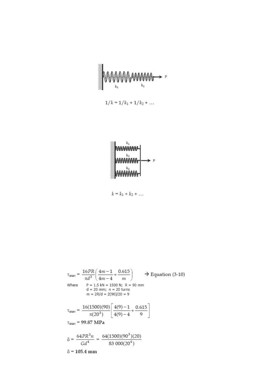
SPRINGS IN SERIES
For two or more springs with spring laid in series, the resulting spring constant k is
given by
where k
1
, k
2
,… are the spring constants for different springs.
SPRINGS IN PARALLEL
Solved Problems in Helical Springs
Problem 343
Determine the maximum shearing stress and elongation in a helical steel spring
composed of 20 turns of 20-mm-diameter wire on a mean radius of 90 mm when the
spring is supporting a load of 1.5 kN. Use Eq. (3-10) and G = 83 GPa.
Solution 343
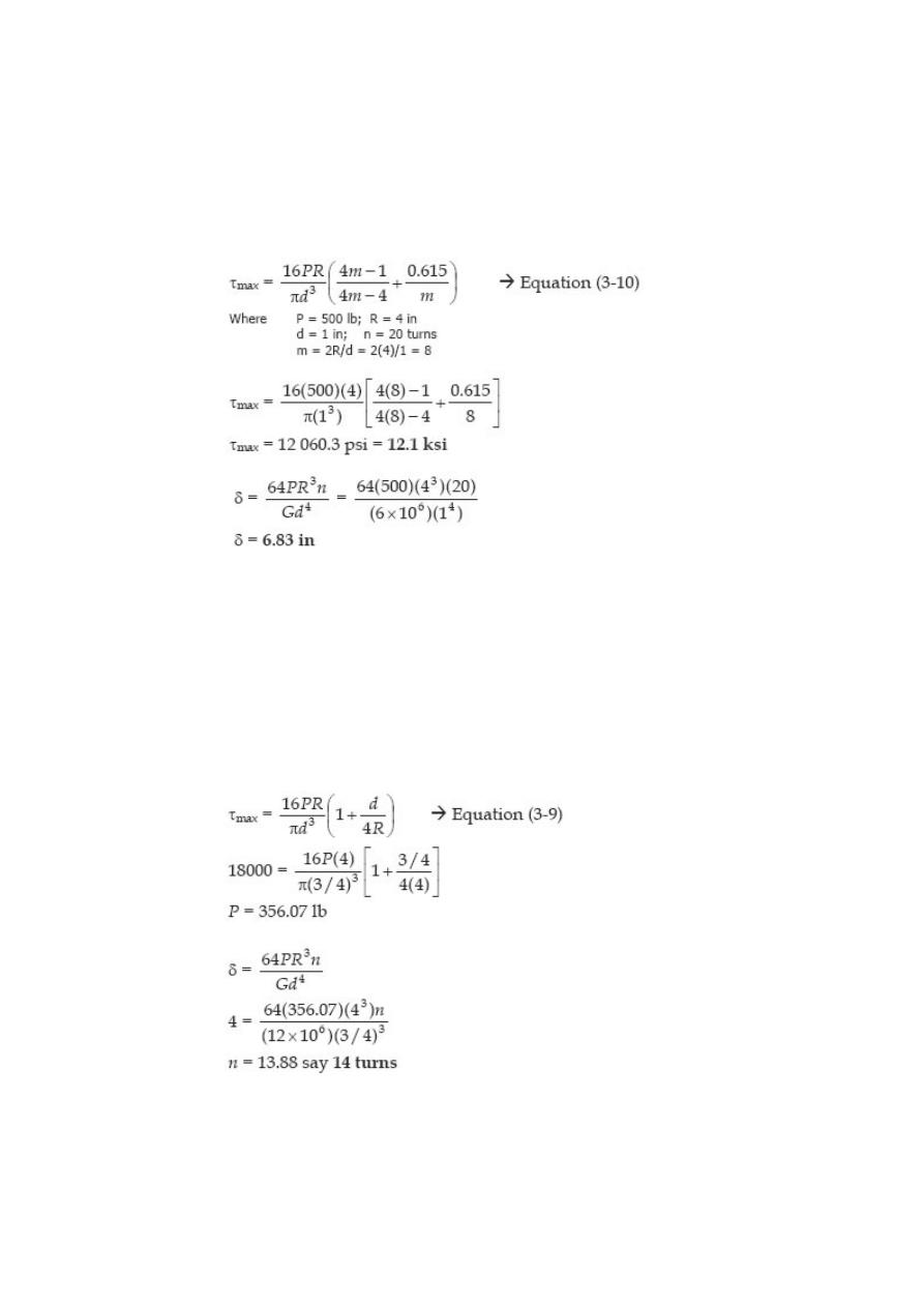
Problem 344
Determine the maximum shearing stress and elongation in a bronze helical spring
composed of 20 turns of 1.0-in.-diameter wire on a mean radius of 4 in. when the
spring is supporting a load of 500 lb. Use Eq. (3-10) and G = 6 × 10
6
psi.
Solution 344
Problem 345
A helical spring is fabricated by wrapping wire ¾ in. in diameter around a forming
cylinder 8 in. in diameter. Compute the number of turns required to permit an
elongation of 4 in. without exceeding a shearing stress of 18 ksi. Use Eq. (3-9) and G =
12 × 106 psi.
Solution 345
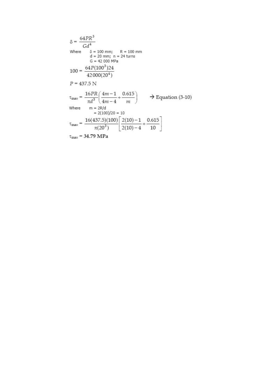
Problem 346
Compute the maximum shearing stress developed in a phosphor bronze spring having
mean diameter of 200 mm and consisting of 24 turns of 200-mm-diameter wire when
the spring is stretched 100 mm. Use Eq. (3-10) and G = 42 GPa.
Solution 346
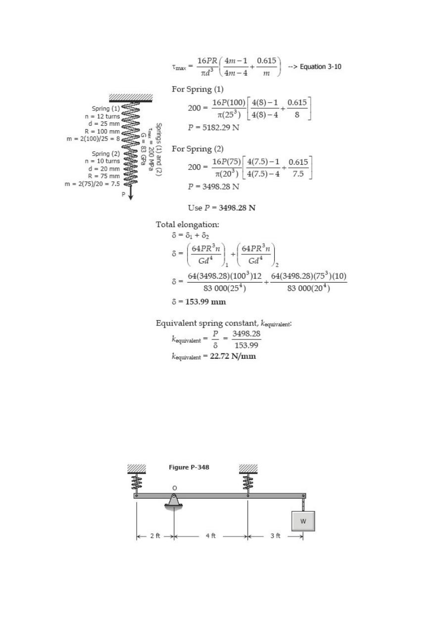
Problem 347
Two steel springs arranged in series as shown in Fig. P-347 supports a load P. The
upper spring has 12 turns of 25-mm-diameter wire on a mean radius of 100 mm. The
lower spring consists of 10 turns of 20-mmdiameter wire on a mean radius of 75 mm. If
the maximum shearing stress in either spring must not exceed 200 MPa, compute the
maximum value of P and the total elongation of the assembly. Use Eq. (3-10) and G =
83 GPa. Compute the equivalent spring constant by dividing the load by the total
elongation.
Solution 347
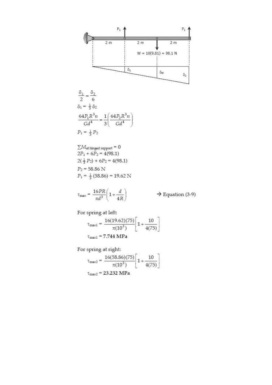
Problem 348
A rigid bar, pinned at O, is supported by two identical springs as shown in Fig. P-348.
Each spring consists of 20 turns of ¾-in-diameter wire having a mean diameter of 6 in.
Determine the maximum load W that may be supported if the shearing stress in the
springs is limited to 20 ksi. Use Eq. (3-9).

Solution 348
Problem 349
A rigid bar, hinged at one end, is supported by two identical springs as shown in Fig. P-
349. Each spring consists of 20 turns of 10-mm wire having a mean diameter of 150
mm. Compute the maximum shearing stress in the springs, using Eq. (3-9). Neglect the
mass of the rigid bar.
Solution 349
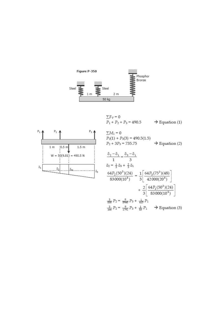
Problem 350
As shown in Fig. P-350, a homogeneous 50-kg rigid block is suspended by the three
springs whose lower ends were originally at the same level. Each steel spring has 24
turns of 10-mm-diameter on a mean diameter of 100 mm, and G = 83 GPa. The bronze
spring has 48 turns of 20-mm-diameter wire on a mean diameter of 150 mm, and G =
42 GPa. Compute the maximum shearing stress in each spring using Eq. (3-9).
Solution 350
Shear & Moment in Beams
DEFINITION OF A BEAM
A beam is a bar subject to forces or couples that lie in a plane containing the
longitudinal of the bar. According to determinacy, a beam may be determinate or
indeterminate.
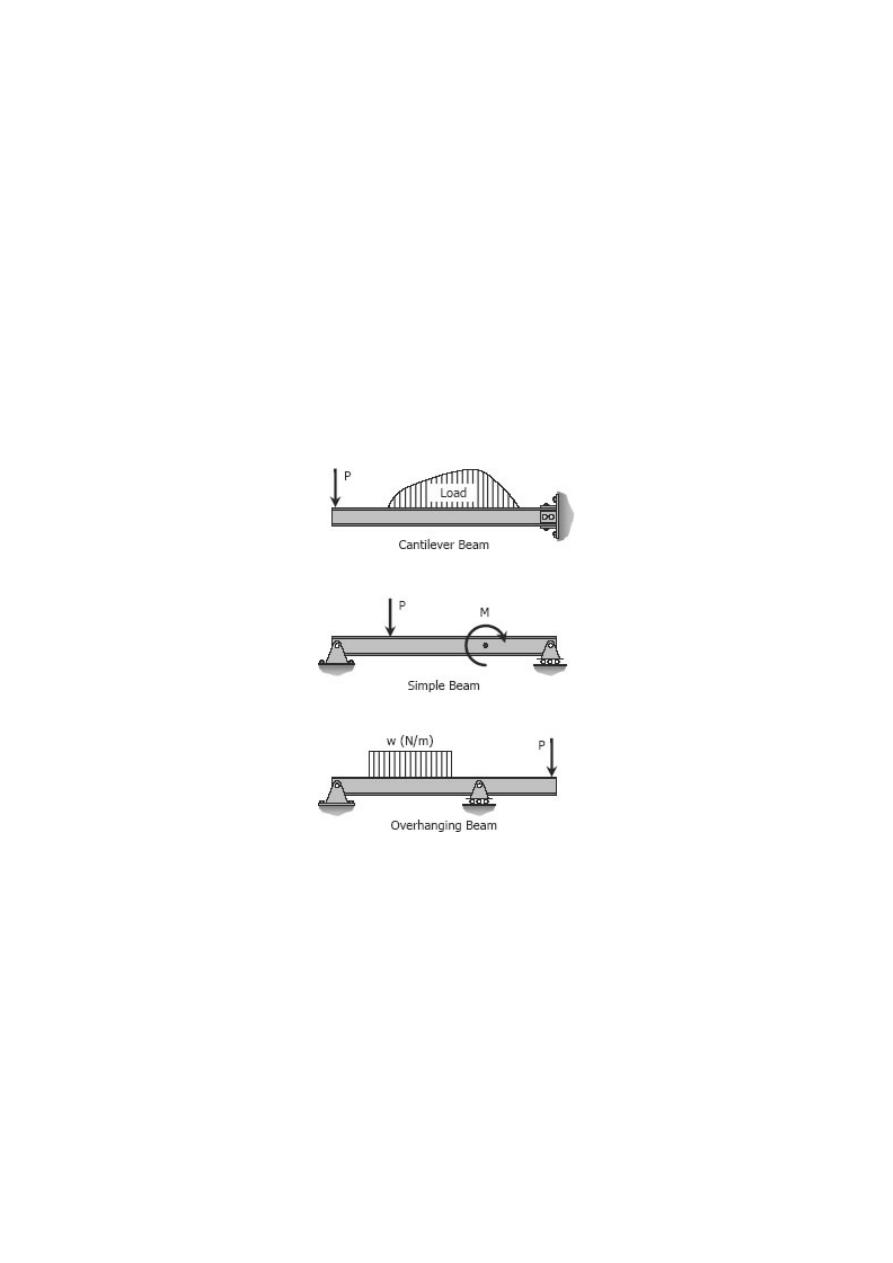
STATICALLY DETERMINATE BEAMS
Statically determinate beams are those beams in which the reactions of the supports
may be determined by the use of the equations of static equilibrium. The beams shown
below are examples of statically determinate beams.
STATICALLY INDETERMINATE BEAMS
If the number of reactions exerted upon a beam exceeds the number of equations in
static equilibrium, the beam is said to be statically indeterminate. In order to solve the
reactions of the beam, the static equations must be supplemented by equations based
upon the elastic deformations of the beam.
The degree of indeterminacy is taken as the difference between the umber of reactions
to the number of equations in static equilibrium that can be applied. In the case of the
propped beam shown, there are three reactions R
1
, R
2
, and M and only two equations
(∑M = 0 and sum;F
v
= 0) can be applied, thus the beam is indeterminate to the first
degree (3 – 2 = 1).
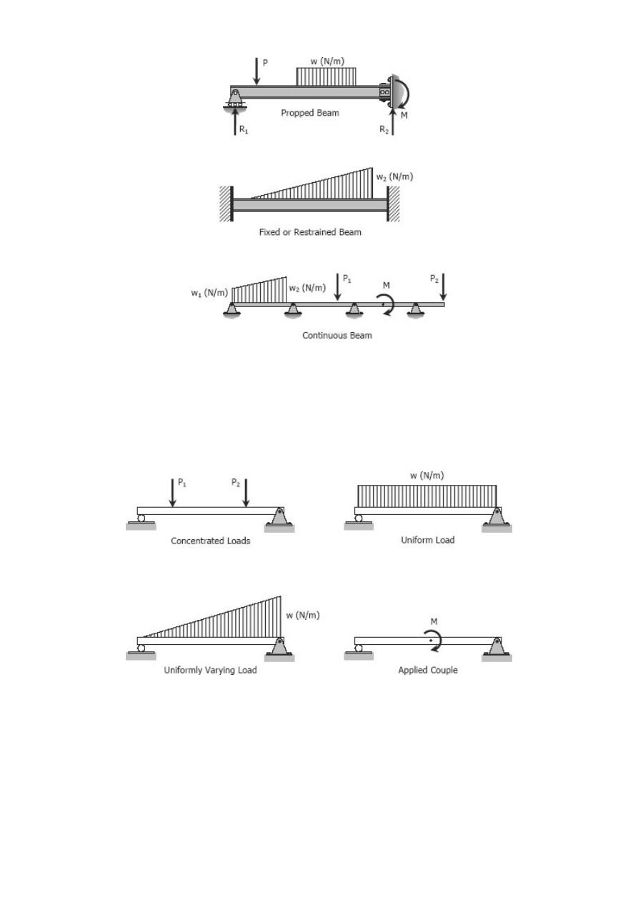
TYPES OF LOADING
Loads applied to the beam may consist of a concentrated load (load applied at a point),
uniform load, uniformly varying load, or an applied couple or moment. These loads are
shown in the following figures.
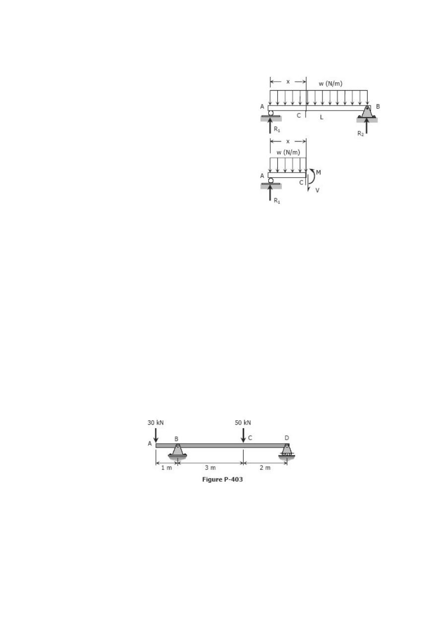
Shear and Moment Diagrams
Consider a simple beam shown of length L that
carries a uniform load of w (N/m) throughout its
length and is held in equilibrium by reactions R
1
and R
2
. Assume that the beam is cut at point
distance of x from he left support and the portion of
the beam to the right of C be removed. The portion
removed must then be replaced by vertical
shearing force V together with a couple M to hold
the left portion of the bar in equilibrium under the
action of R
1
and wx. The couple M is called the resisting moment or moment and the
force V is called the resisting shear or shear. The sign of V and M are taken to be
positive if they have the senses ind
C a
icated above.
Solved Problems in Shear and Moment Diagrams
INSTRUCTION
Write shear and moment equations for the beams in the following problems. In each
problem, let x be the distance measured from left end of the beam. Also, draw shear
and moment diagrams, specifying values at all change of loading positions and at points
of zero shear. Neglect the mass of the beam in each problem.
Problem 403
Beam loaded as shown in Fig. P-403.
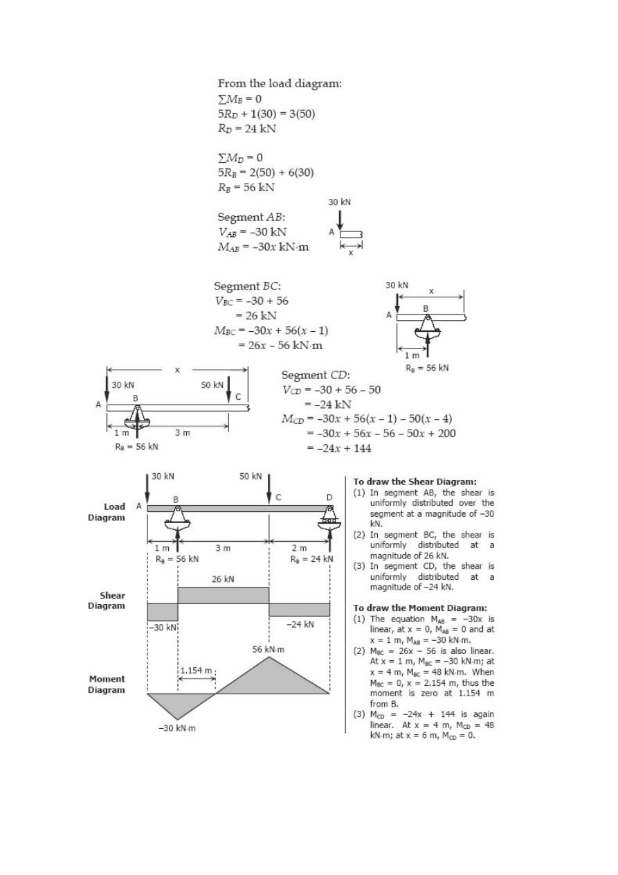
Solution 403
Problem 404
Beam loaded as shown in Fig. P-404.
Solution 404
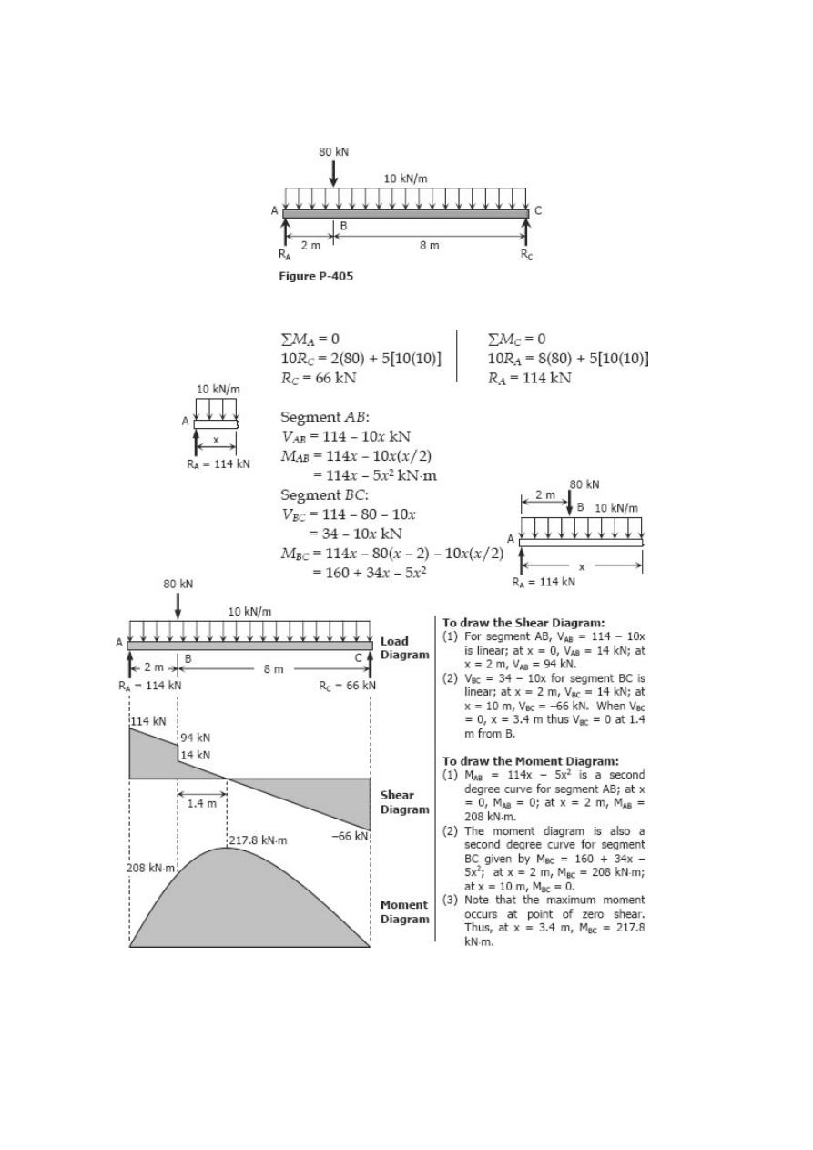
Problem 405
Beam loaded as shown in Fig. P-405.
Solution 405
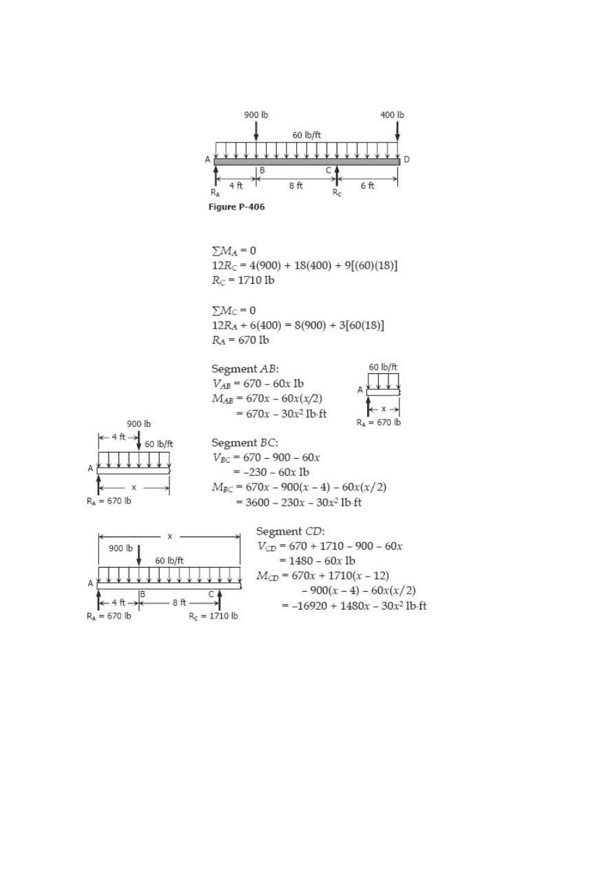
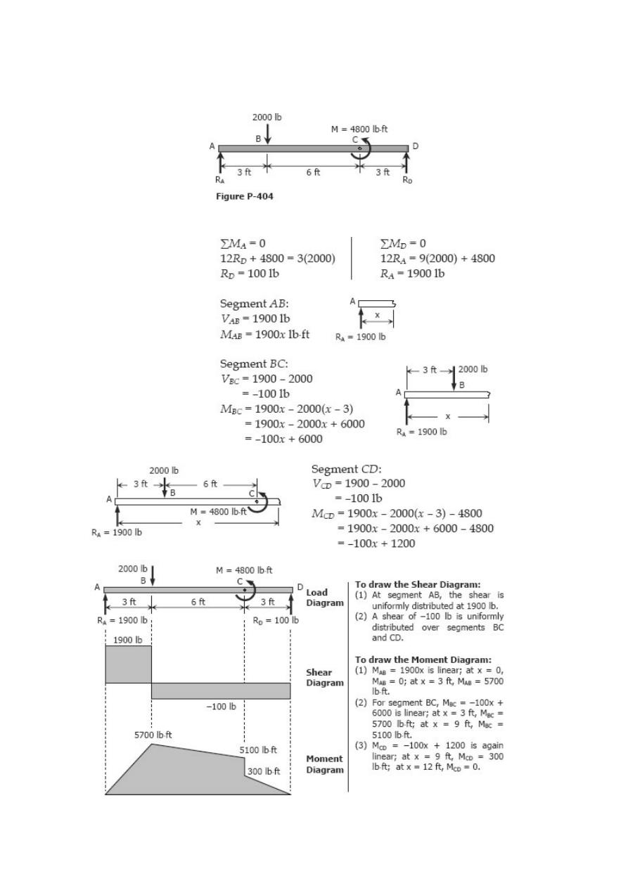
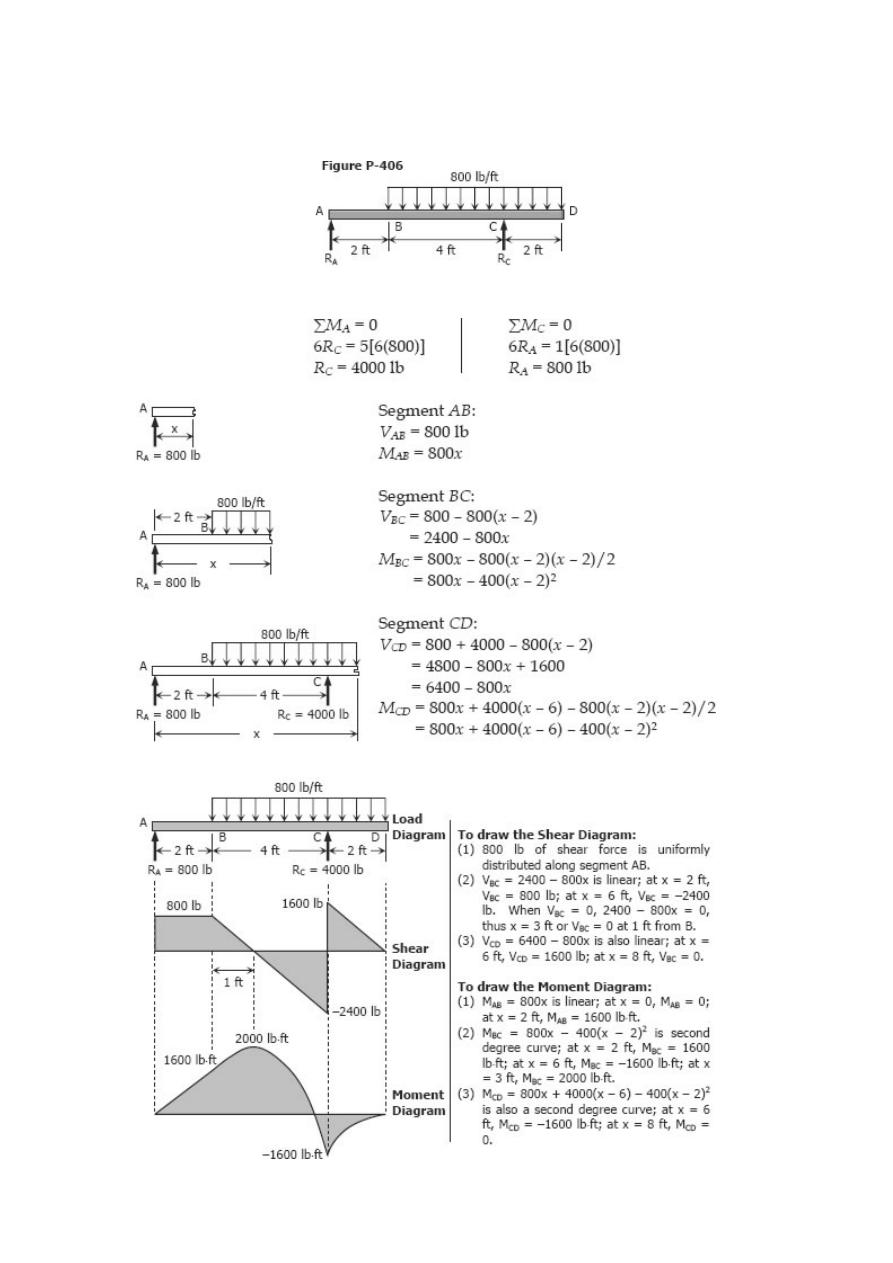
Problem 406
Beam loaded as shown in Fig. P-406.
Solution 406
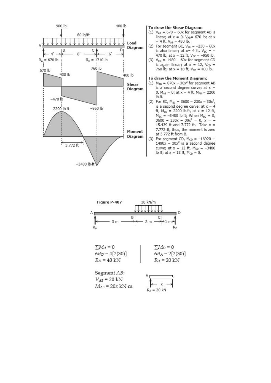
Problem 407
Beam loaded as shown in Fig. P-407.
Solution 407
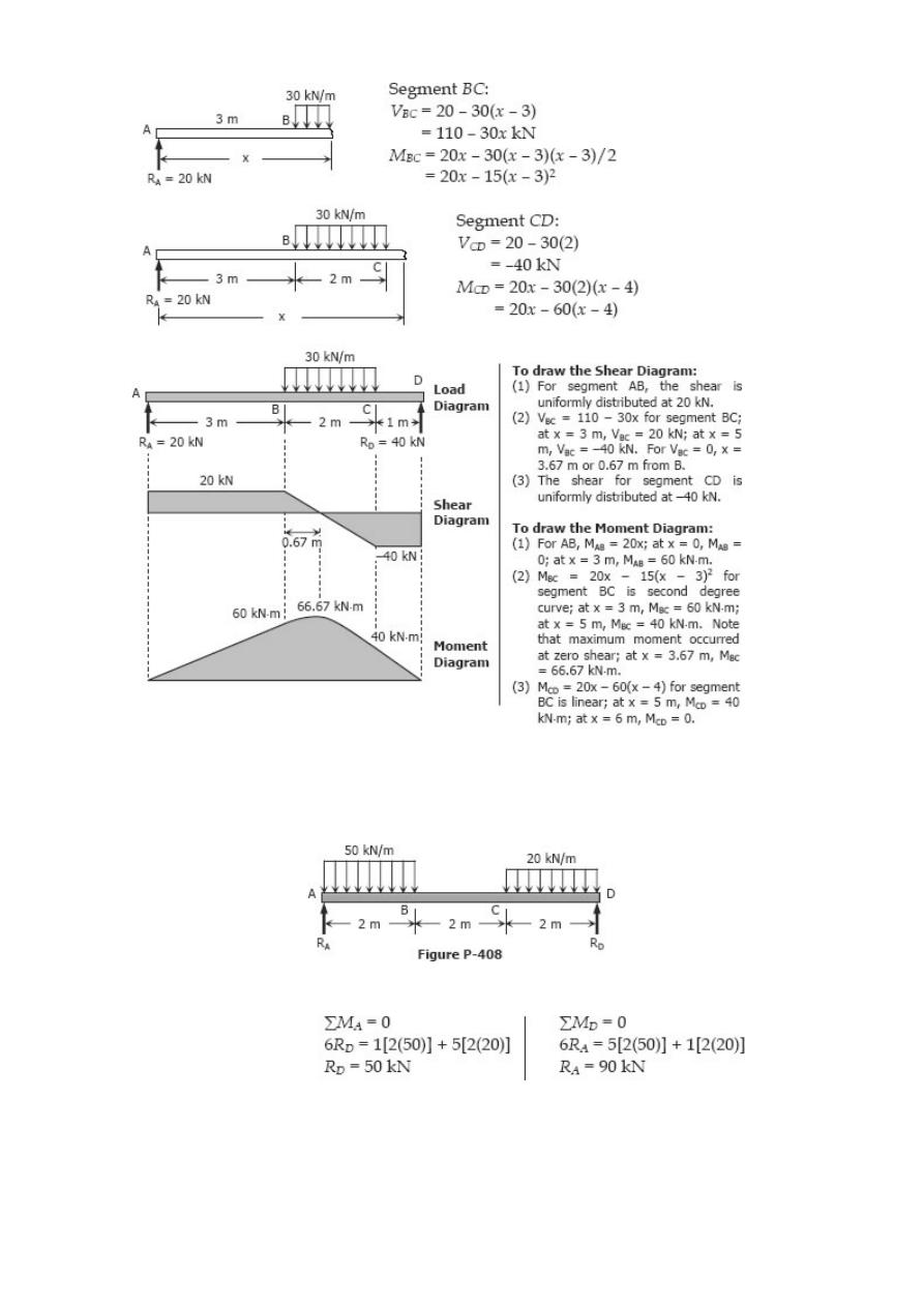
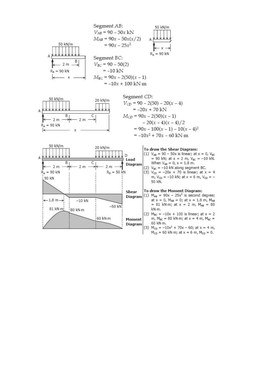
Problem 408
Beam loaded as shown in Fig. P-408.
Solution 408
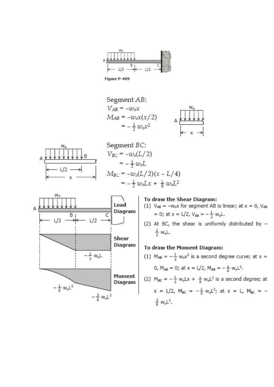
Problem 409
Cantilever beam loaded as shown in Fig. P-409.
Solution 409
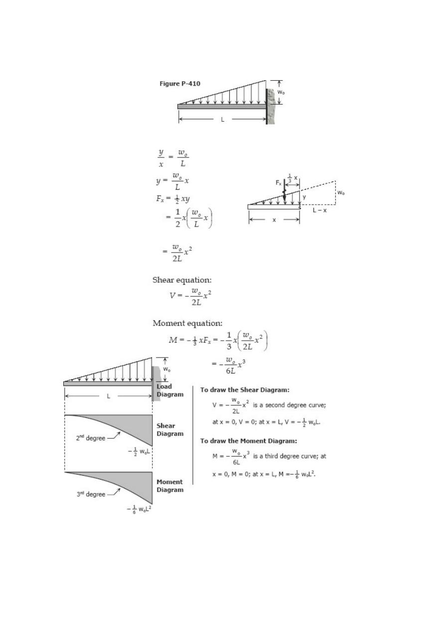
Problem 410
Cantilever beam carrying the uniformly varying load shown in Fig. P-410.
Solution 410
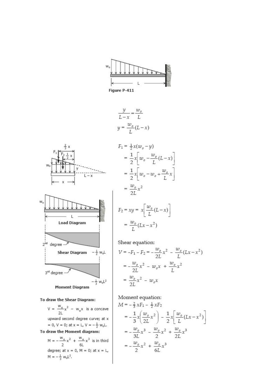
Problem 411
Cantilever beam carrying a distributed load with intensity varying from wo at the free
end to zero at the wall, as shown in Fig. P-411.
Solution 411
Problem 412
Beam loaded as shown in Fig. P-412.
Solution 412
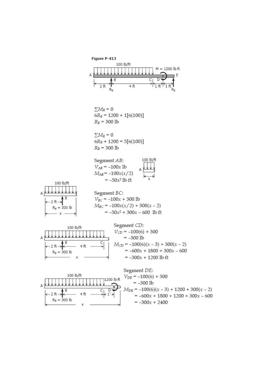
Problem 413
Beam loaded as shown in Fig. P-413.
Solution 413
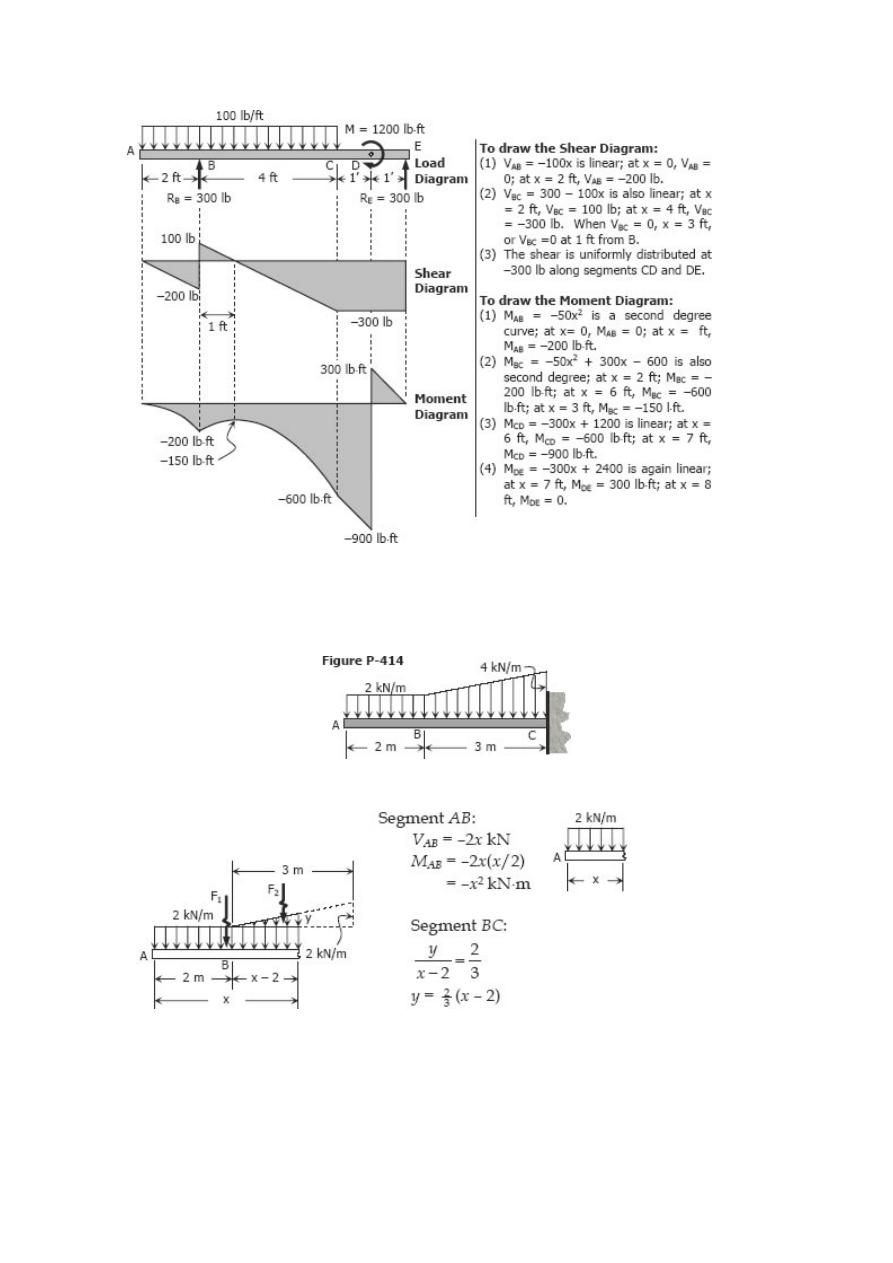
Problem 414
Cantilever beam carrying the load shown in Fig. P-414.
Solution 414
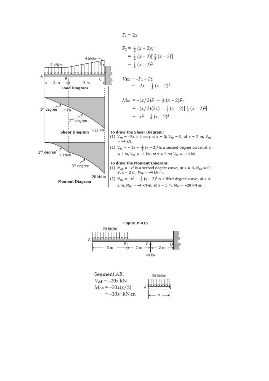
Problem 415
Cantilever beam loaded as shown in Fig. P-415.
Solution 415
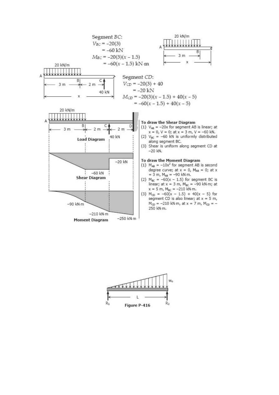
Problem 416
Beam carrying uniformly varying load shown in Fig. P-416.
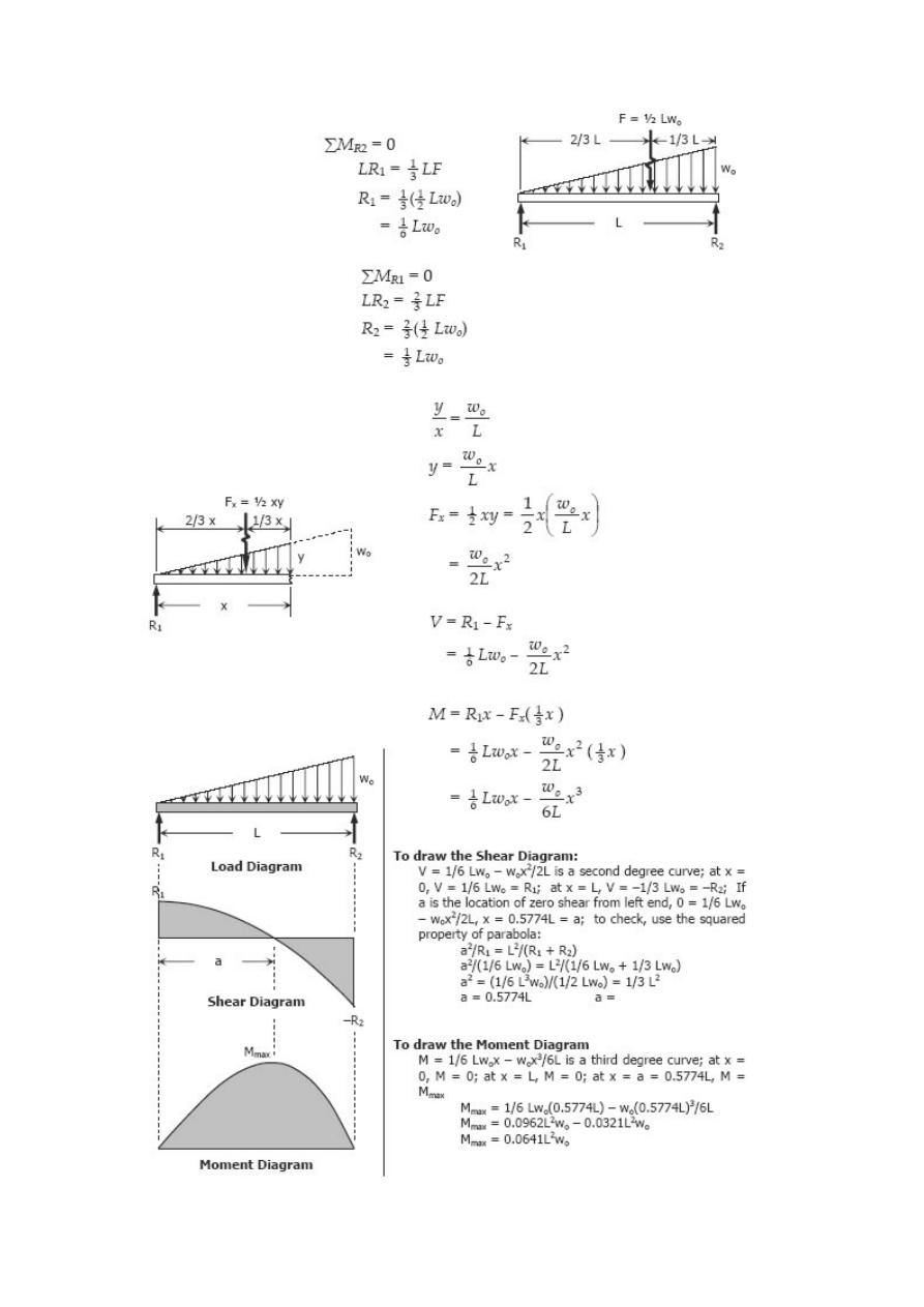
Solution 416
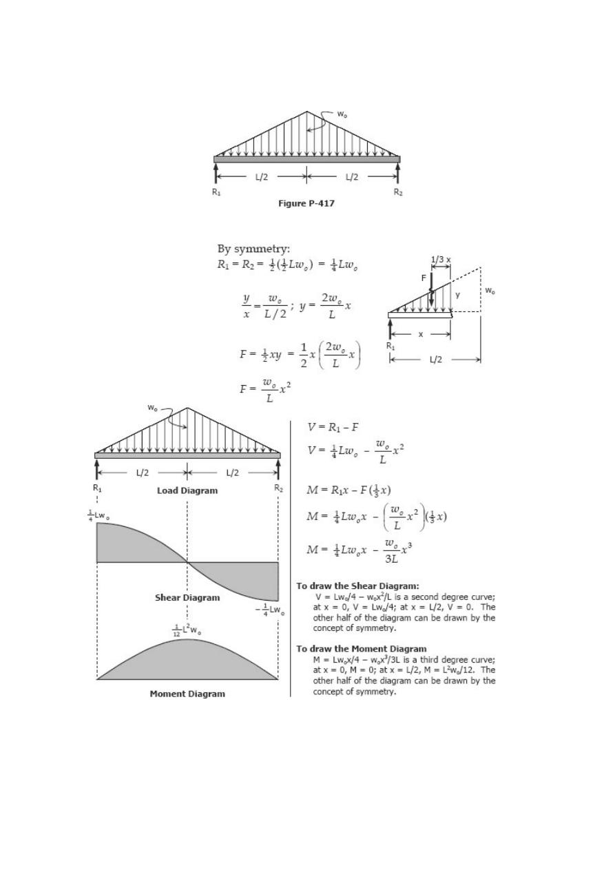
Problem 417
Beam carrying the triangular loading shown in Fig. P- 417.
Solution 417
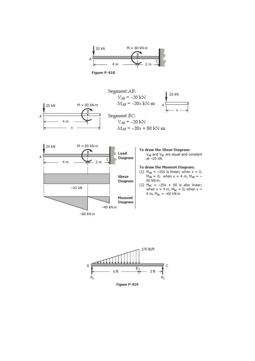
Problem 418
Cantilever beam loaded as shown in Fig. P-418.
Solution 418
Problem 419
Beam loaded as shown in Fig. P-419.
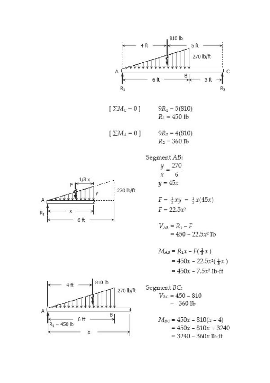
Solution 419
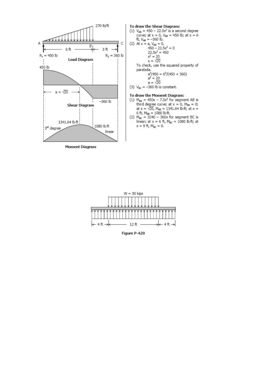
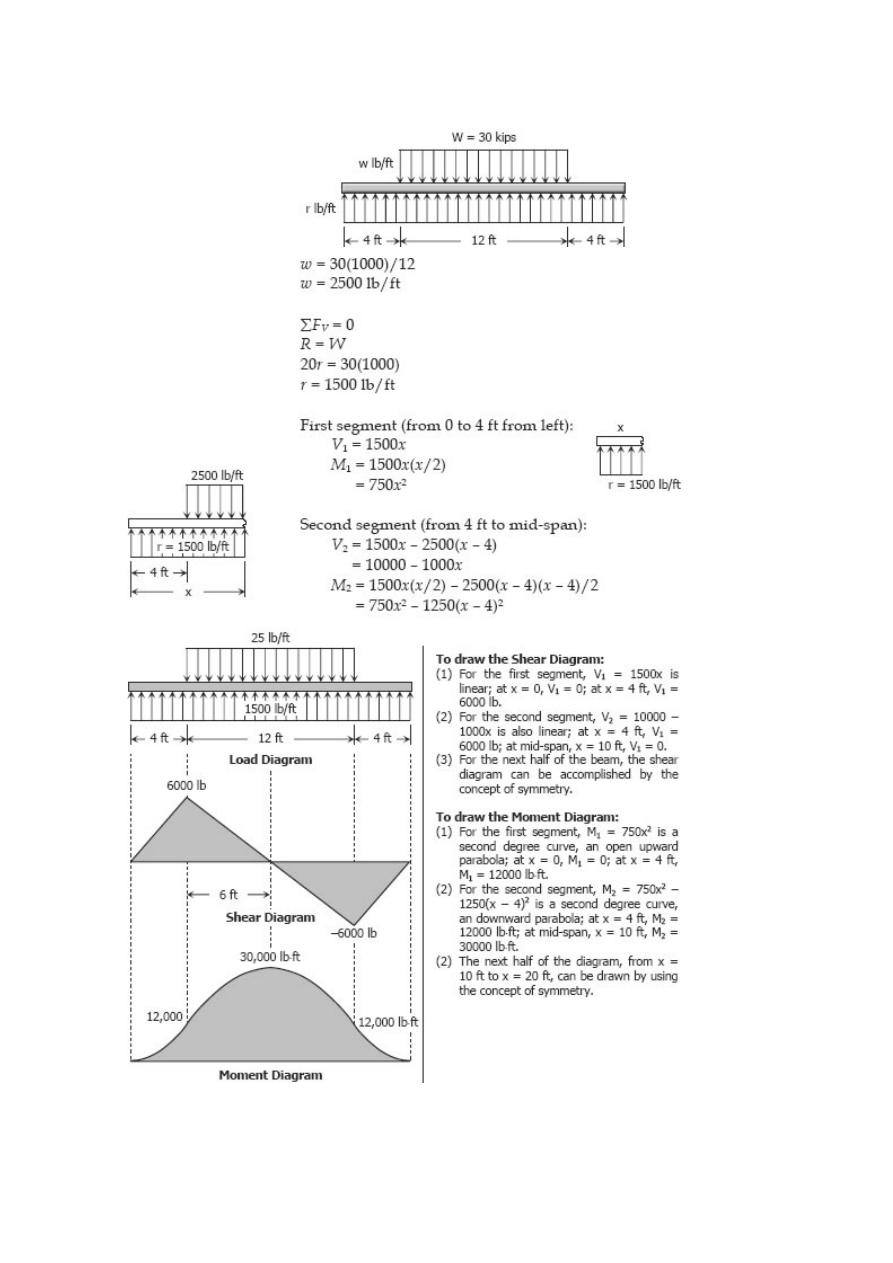
Problem 420
A total distributed load of 30 kips supported by a uniformly distributed reaction as
shown in Fig. P-420.
Solution 420
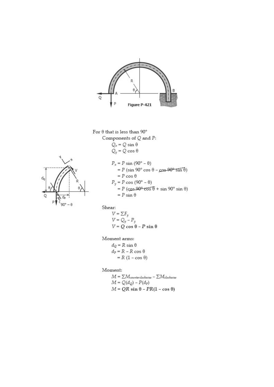
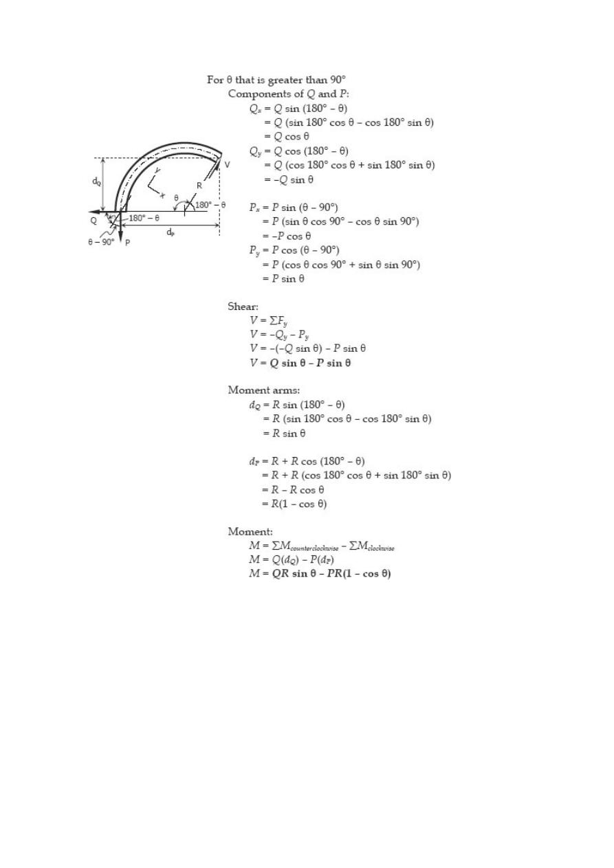
Problem 421
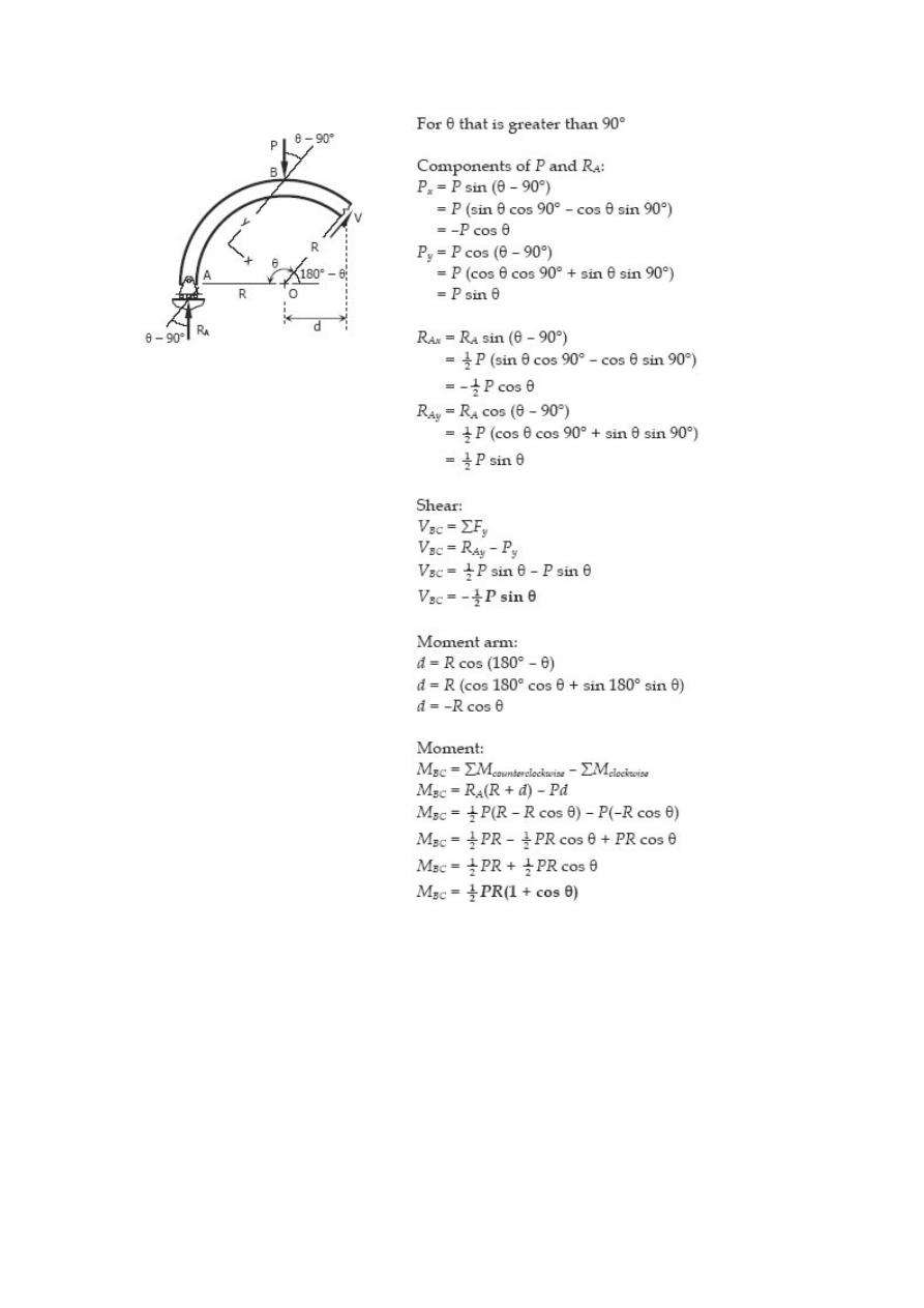
Write the shear and moment equations as functions of the angle θ for the built-in arch
shown in Fig. P-421.
Solution 421
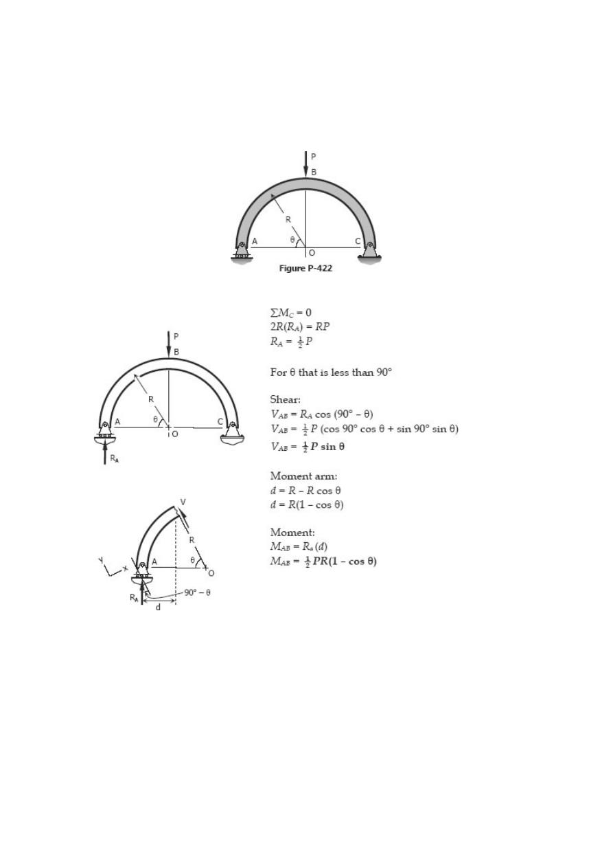
Problem 422
Write the shear and moment equations for the semicircular arch as shown in Fig. P-422
if (a) the load P is vertical as shown, and (b) the load is applied horizontally to the left
at the top of the arch.
Solution 422
Relationship between Load, Shear, and Moment
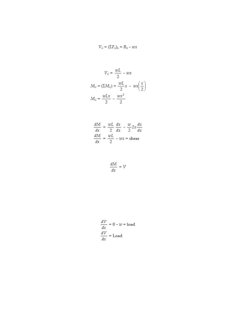
The vertical shear at C in the figure shown in previous section is taken as
where R
1
= R
2
= wL/2
If we differentiate M with respect to x:
thus,
Thus, the rate of change of the bending moment with respect to x is equal to the
shearing force, or the slope of the moment diagram at the given point is the
shear at that point.
Differentiate V with respect to x gives
Thus, the rate of change of the shearing force with respect to x is equal to the load or
the slope of the shear diagram at a given point equals the load at that point.
PROPERTIES OF SHEAR AND MOMENT DIAGRAMS
The following are some important properties of shear and moment diagrams:
1. The area of the shear diagram to the left or to the right of the section is equal to
the moment at that section.
2. The slope of the moment diagram at a given point is the shear at that point.
3. The slope of the shear diagram at a given point equals the load at that point.
4. The maximum moment occurs at the point of zero shears.
This is in reference to property number 2, that when the
shear (also the slope of the moment diagram) is zero, the
tangent drawn to the moment diagram is horizontal.
5. When the shear diagram is increasing, the moment diagram is concave upward.
6. When the shear diagram is decreasing, the moment diagram is concave
downward.
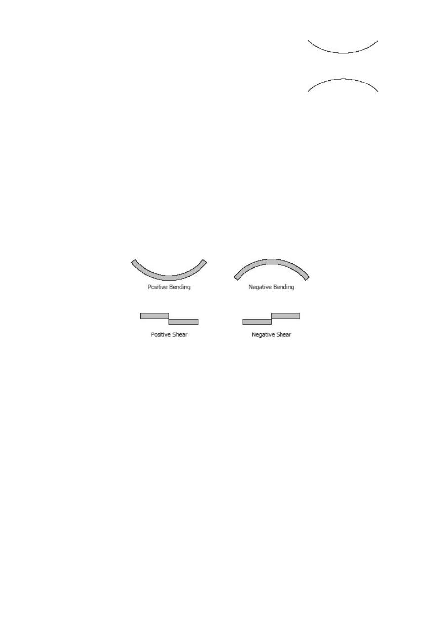
SIGN CONVENTIONS
The customary sign conventions for shearing force and bending moment are
represented by the figures below. A force that tends to bend the beam downward is said
to produce a positive bending moment. A force that tends to shear the left portion of
the beam upward with respect to the right portion is said to produce a positive shearing
force.
An easier way of determining the sign of the bending moment at any section is that
upward forces always cause positive bending moments regardless of whether they act
to the left or to the right of the exploratory section.
Solved Problems in Relationship between Load, Shear, and Moment
INSTRUCTION
Without writing shear and moment equations, draw the shear and moment diagrams for
the beams specified in the following problems. Give numerical values at all change of
loading positions and at all points of zero shear. (Note to instructor: Problems 403 to
420 may also be assigned for solution by semi graphical method describes in this
article.)
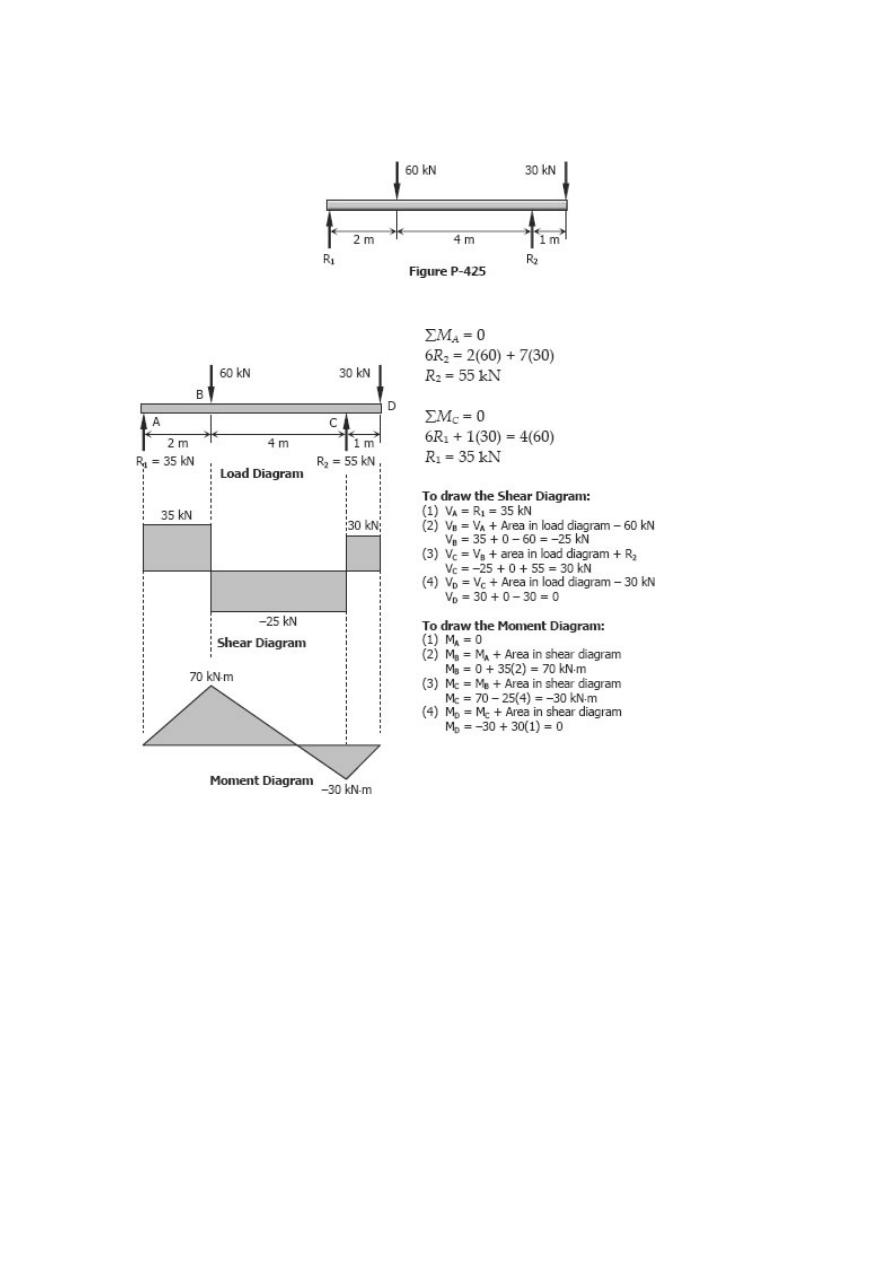
Problem 425
Beam loaded as shown in Fig. P-425.
Solution 425
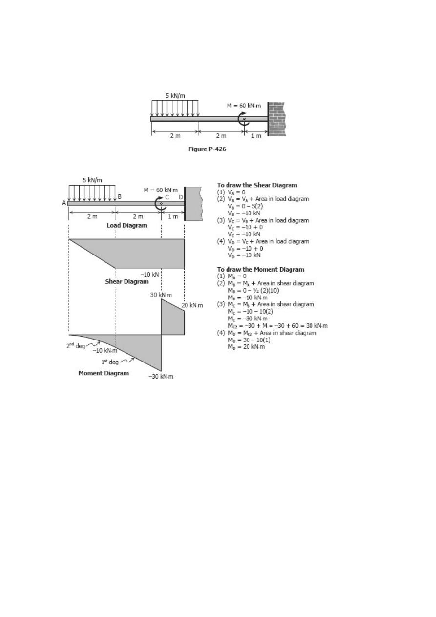
Problem 426
Cantilever beam acted upon by a uniformly distributed load and a couple as shown in
Fig. P-426.
Solution 426
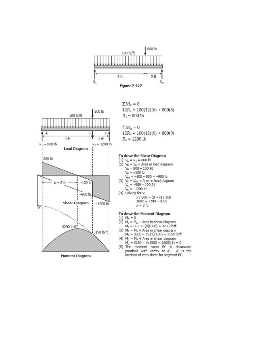
Problem 427
Beam loaded as shown in Fig. P-427.
Solution 427
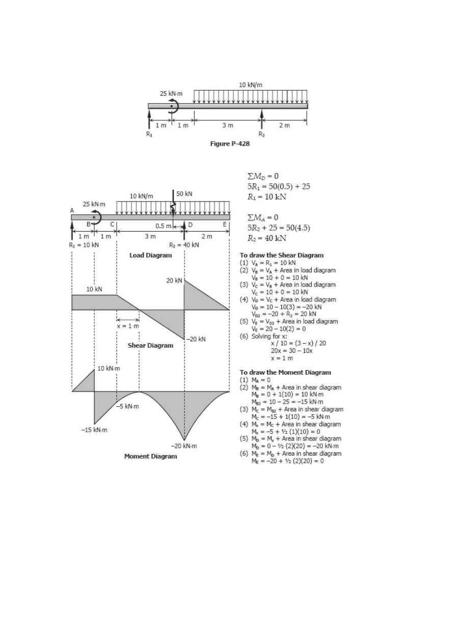
Problem 428
Beam loaded as shown in Fig. P-428.
Solution 428
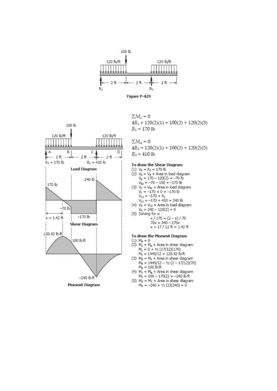
Problem 429
Beam loaded as shown in Fig. P-429.
Solution 429
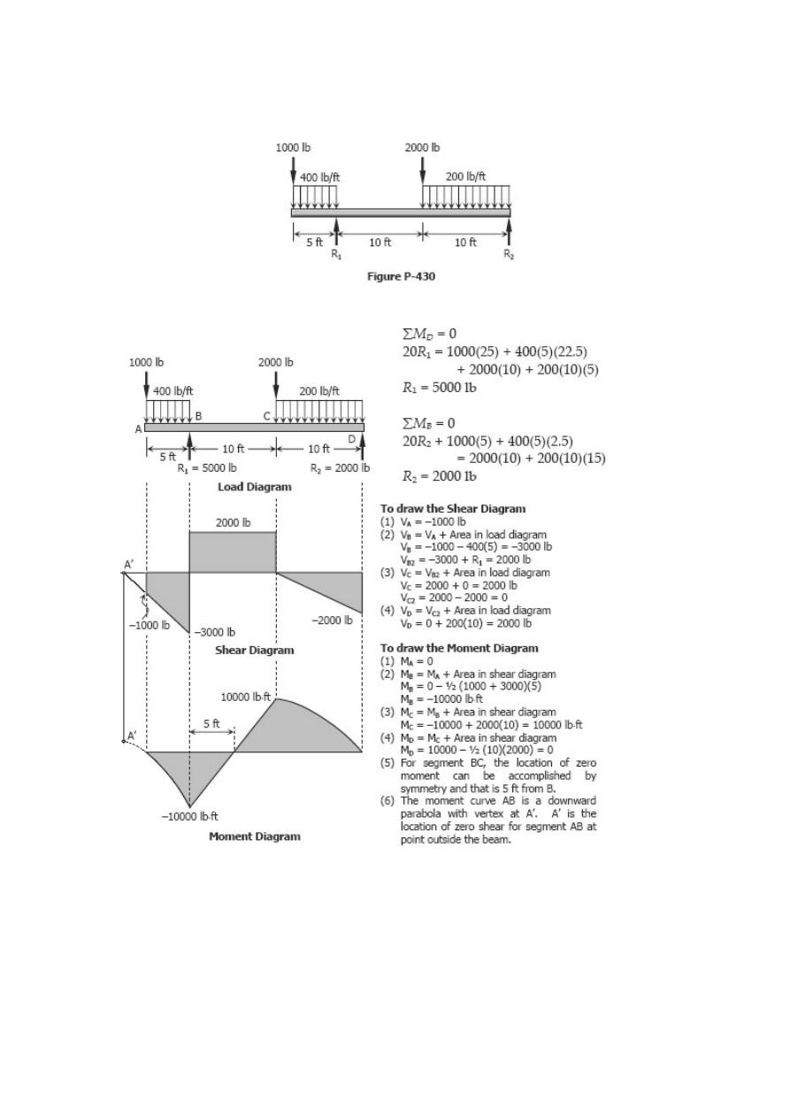
Problem 430
Beam loaded as shown in P-430.
Solution 430
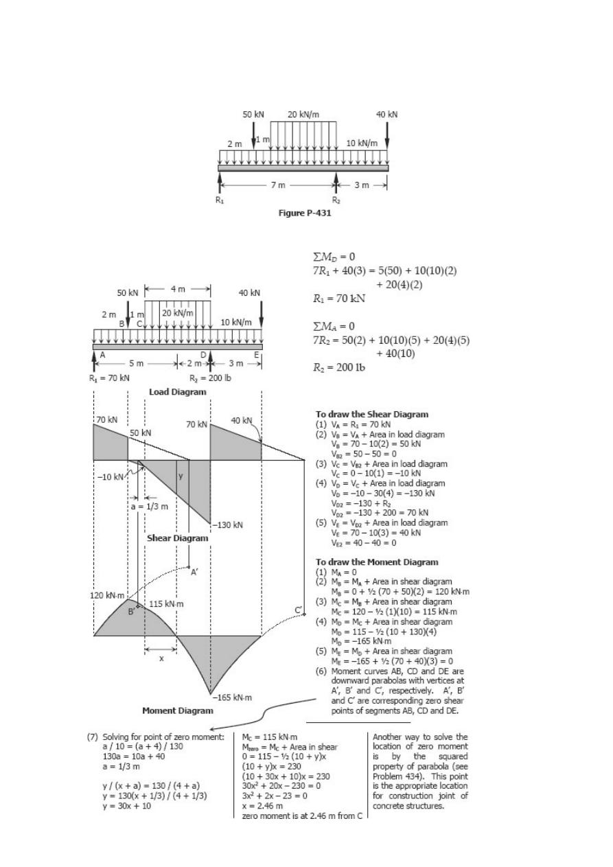
Problem 431
Beam loaded as shown in Fig. P-431.
Solution 431
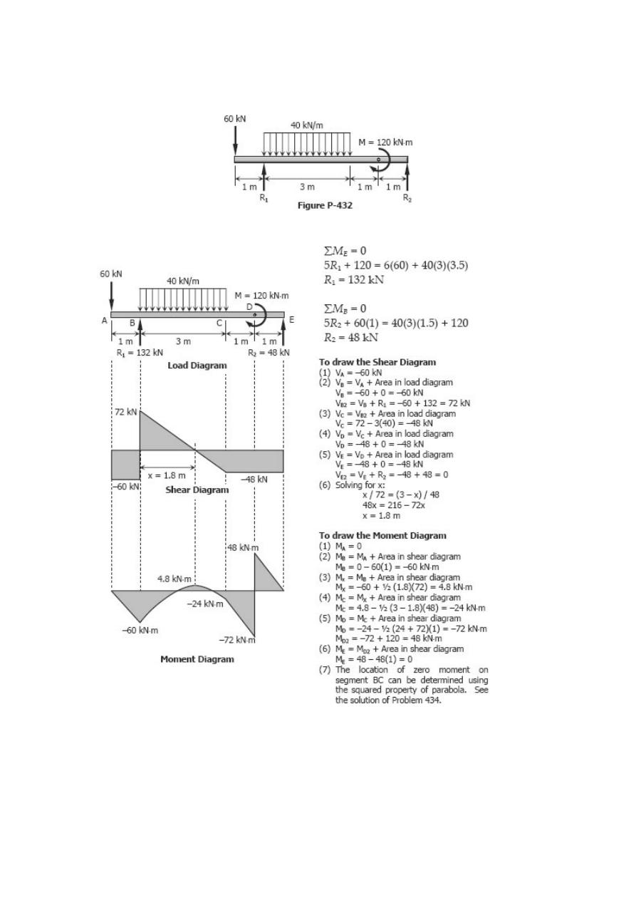
Problem 432
Beam loaded as shown in Fig. P-432.
Solution 432
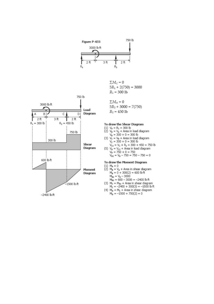
Problem 433
Overhang beam loaded by a force and a couple as shown in Fig. P-433.
Solution 433
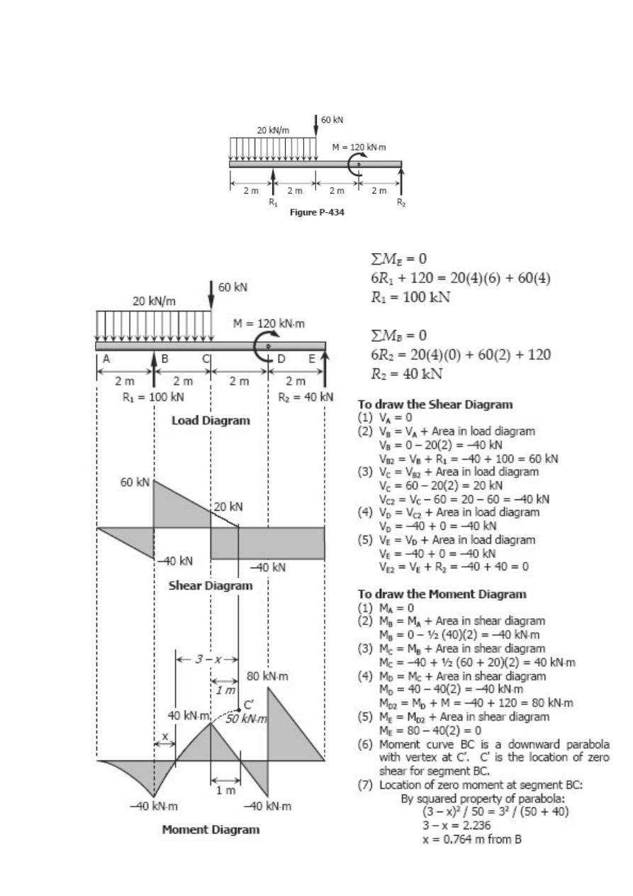
Problem 434
Beam loaded as shown in Fig. P-434.
Solution 434
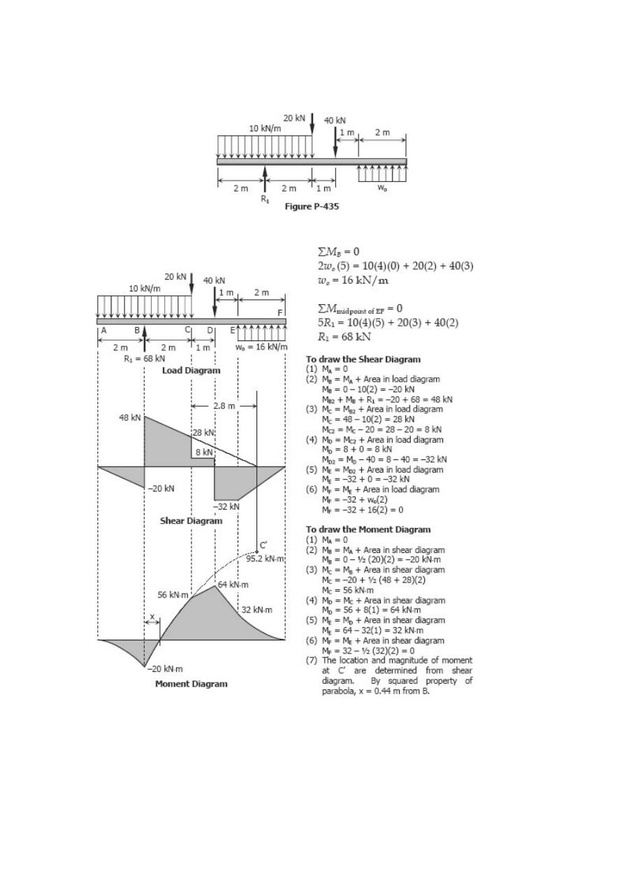
Problem 435
Beam loaded and supported as shown in Fig. P-435.
Solution 435
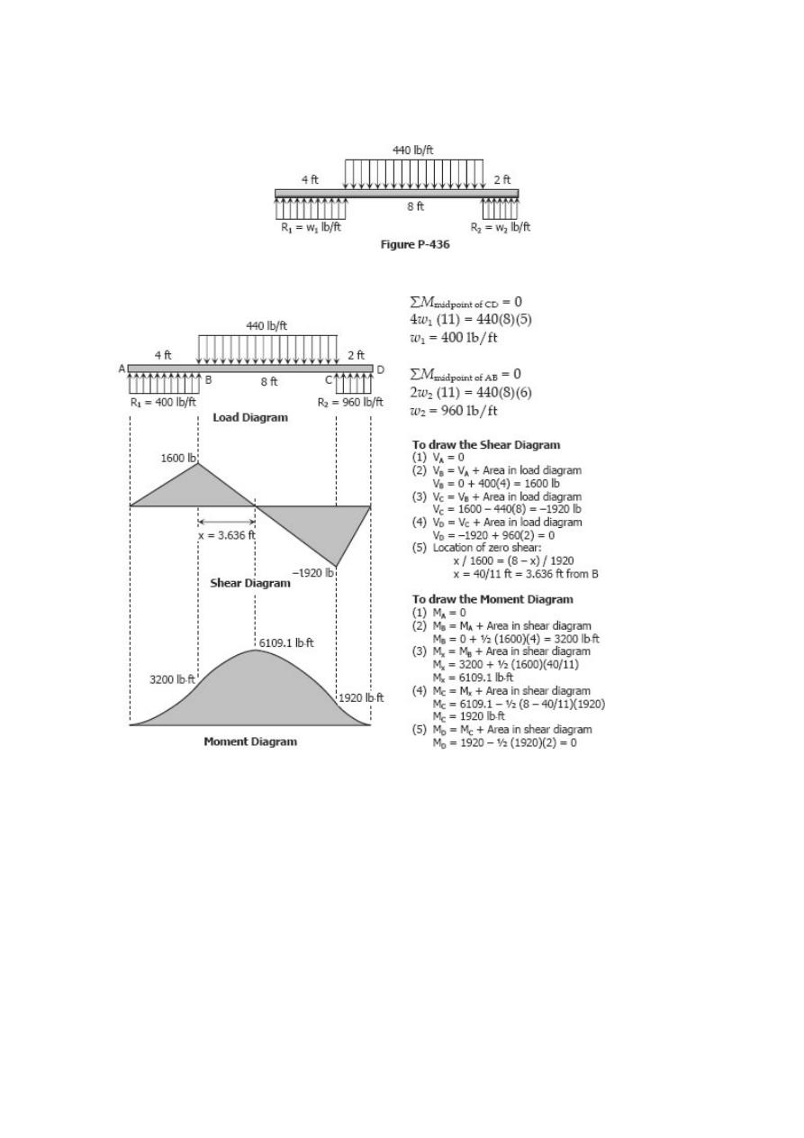
Problem 436
A distributed load is supported by two distributedreactions as shown in Fig. P-436.
Solution 436
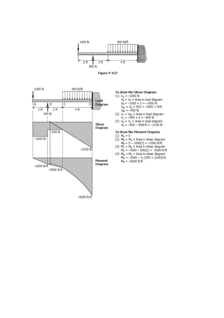
Problem 437
Cantilever beam loaded as shown in Fig. P-437
Solution 437
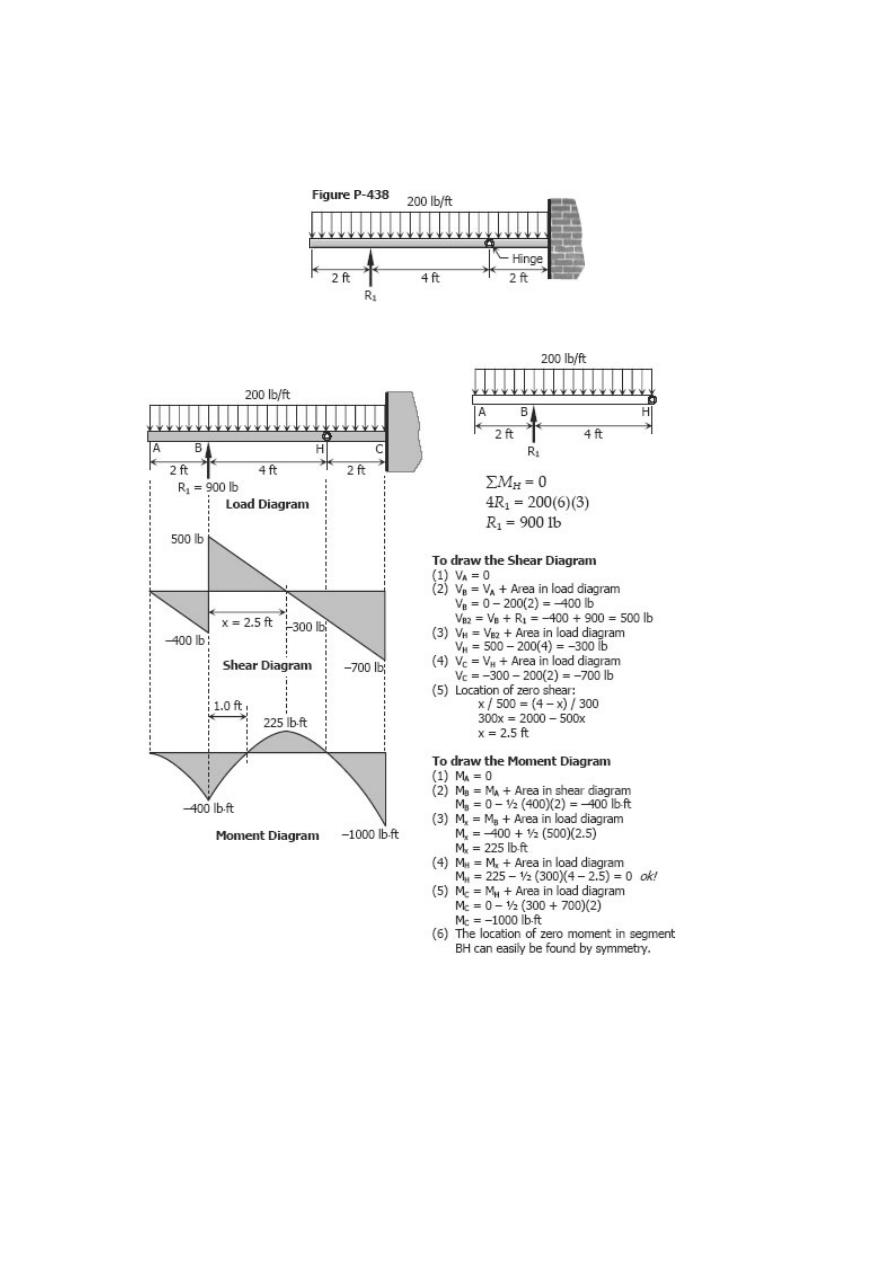
Problem 438
The beam loaded as shown in Fig. P-438 consists of two segments joined by a
frictionless hinge at which the bending moment is zero.
Solution 438
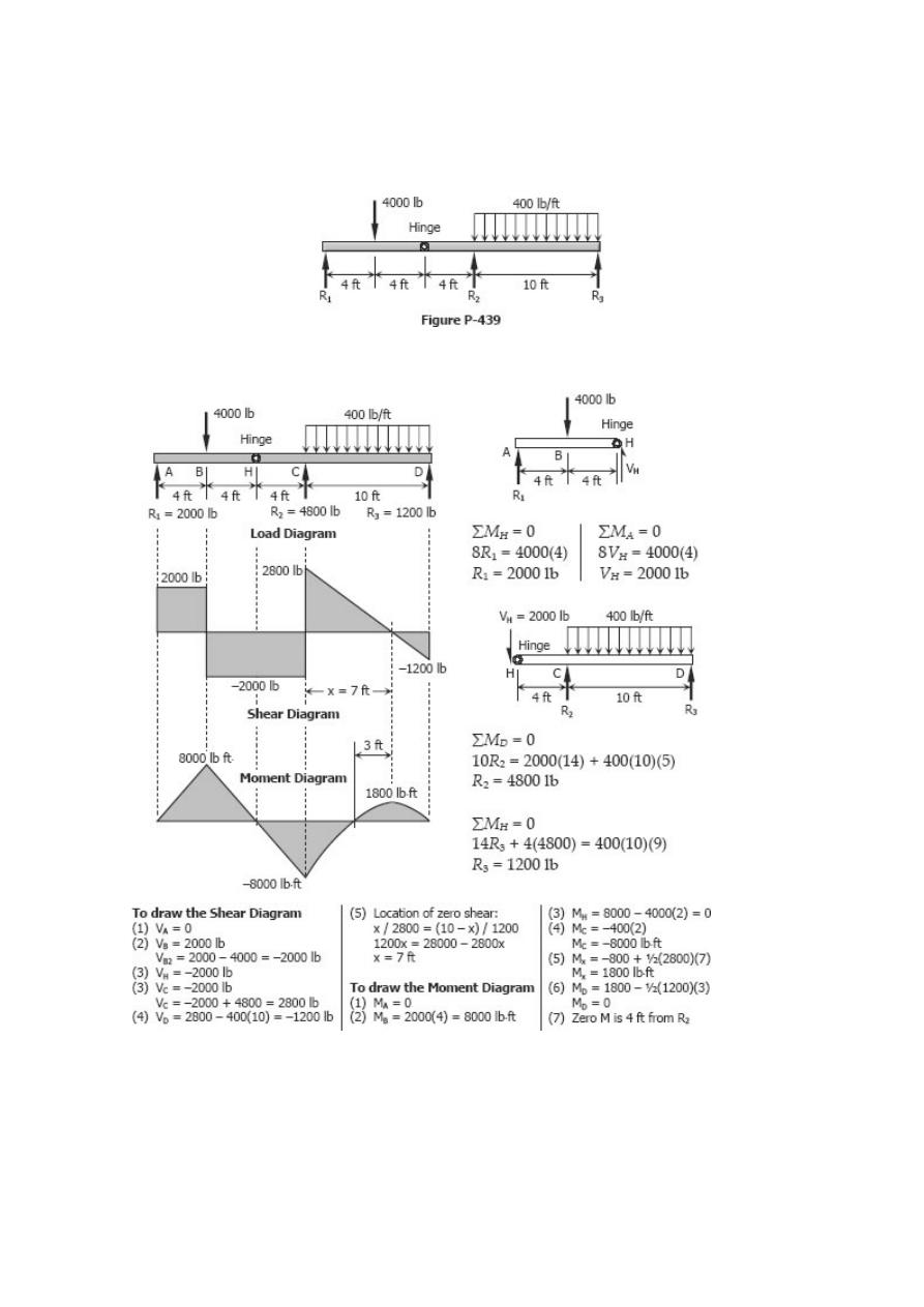
Problem 439
A beam supported on three reactions as shown in Fig. P-439 consists of two segments
joined by frictionless hinge at which the bending moment is zero.
Solution 439
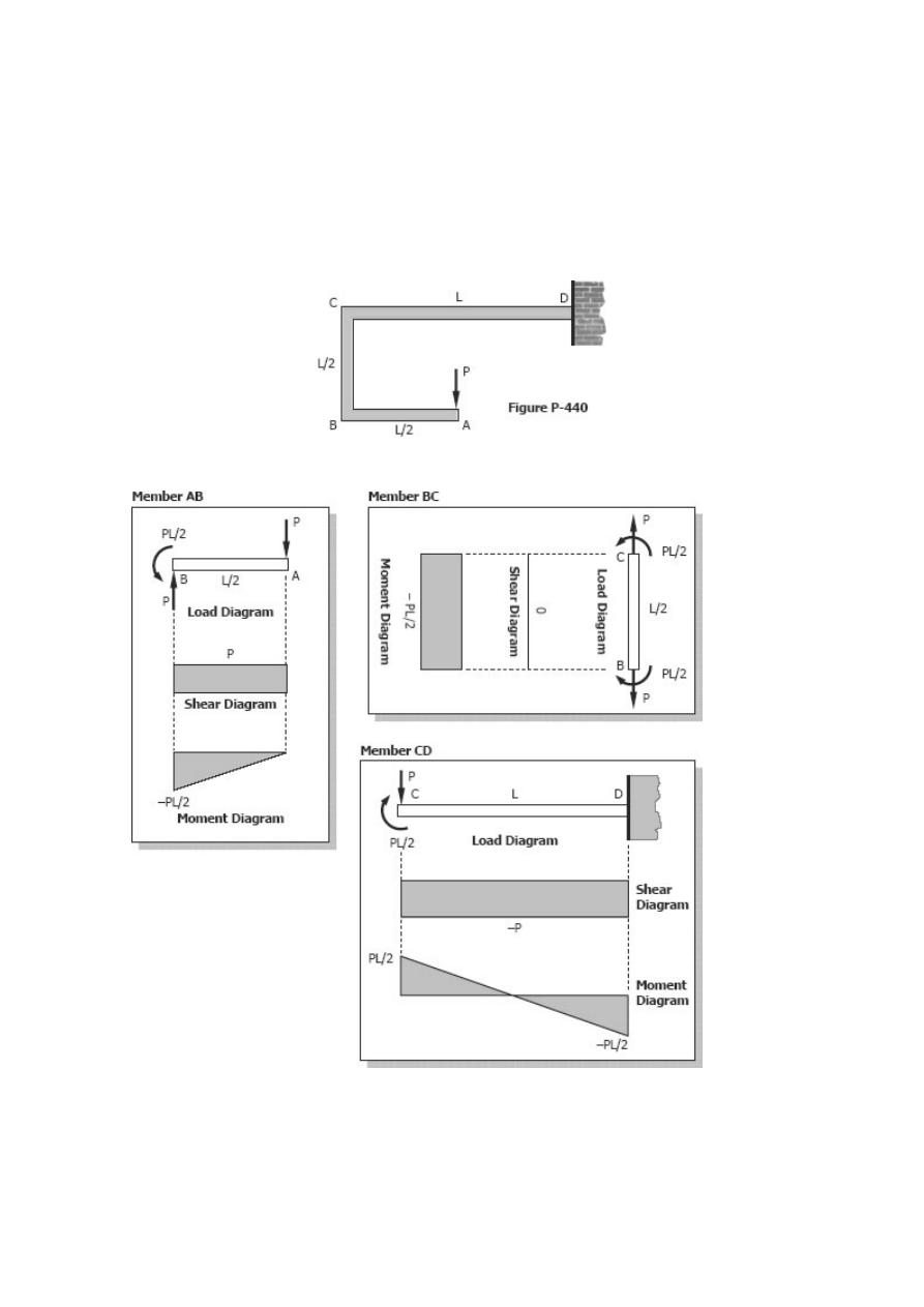
Problem 440
A frame ABCD, with rigid corners at B and C, supports the concentrated load as shown
in Fig. P-440. (Draw shear and moment diagrams for each of the three parts of the
frame.)
Solution 440
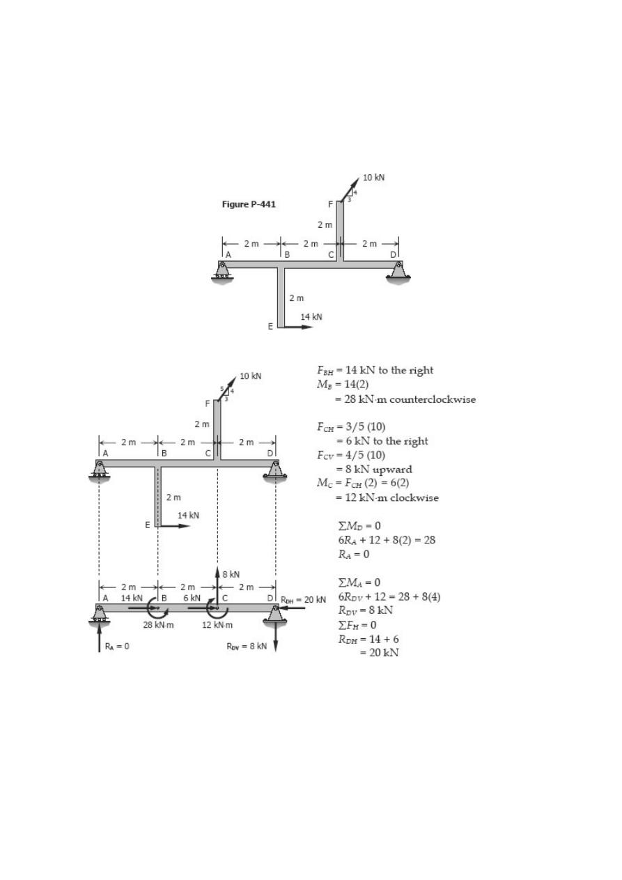
Problem 441
A beam ABCD is supported by a roller at A and a hinge at D. It is subjected to the loads
441, which act at the ends of the vertical members
shown in Fig. P-
BE and CF. These vertical members are rigidly attached to the beam at B and C. (Draw
shear and moment diagrams for the beam ABCD only.)
Solution 441
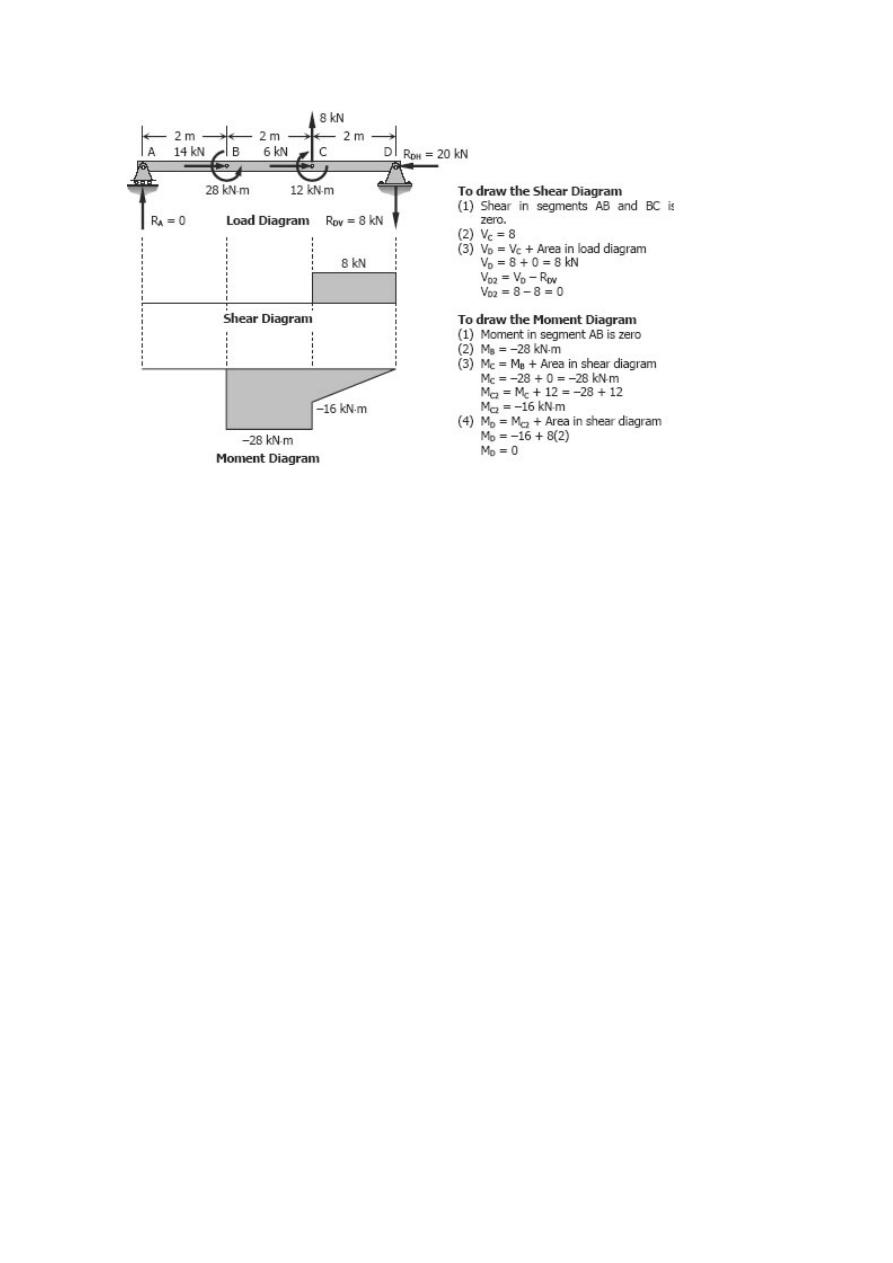
Problem 442
Beam carrying the uniformly varying load shown in Fig. P-442.
Solution 442
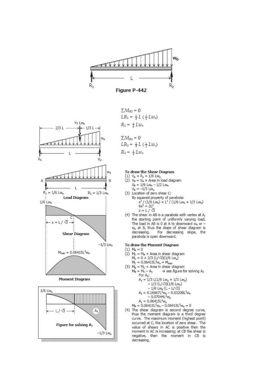
Problem 443
Beam carrying the triangular loads shown in Fig. P-443.
Solution 443
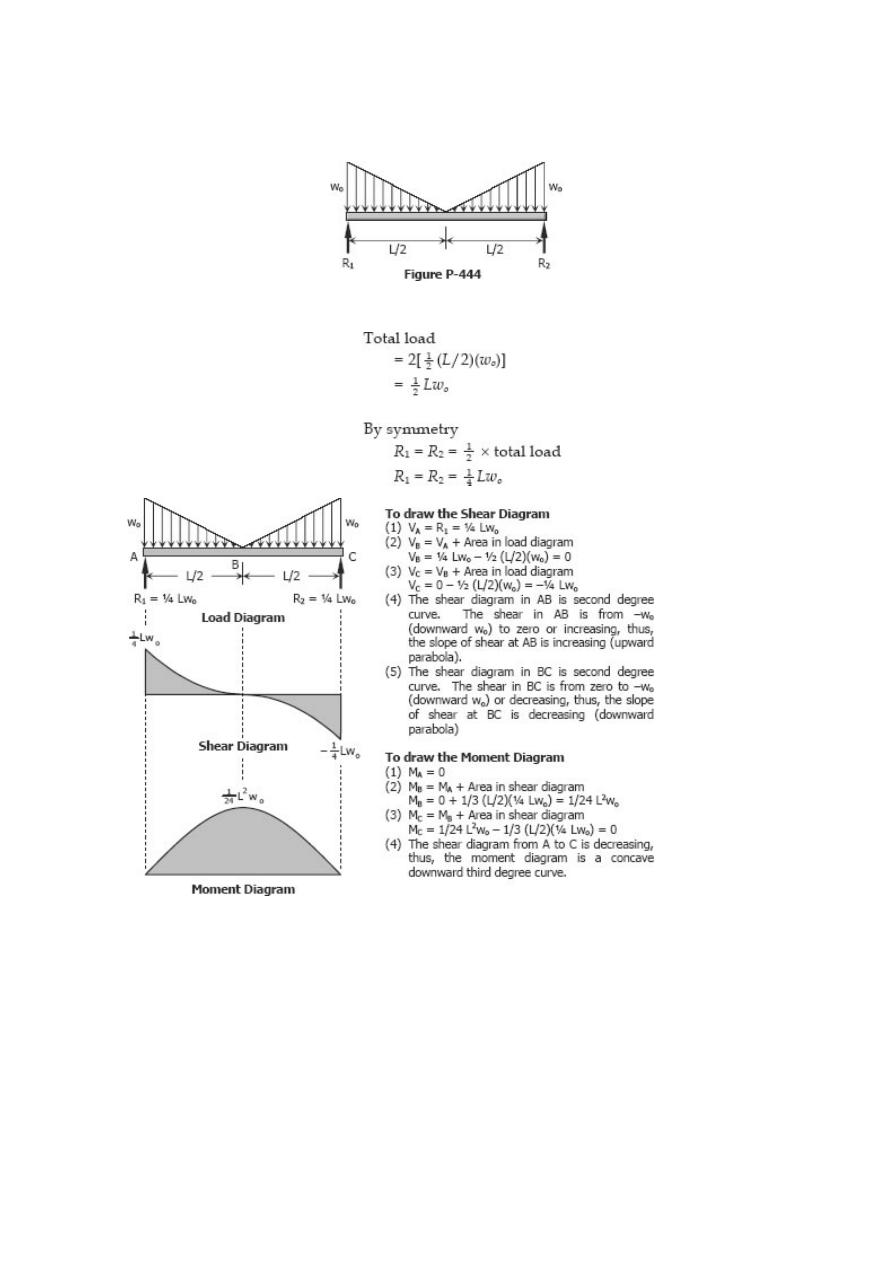
Problem 444
Beam loaded as shown in Fig. P-444.
Solution 444
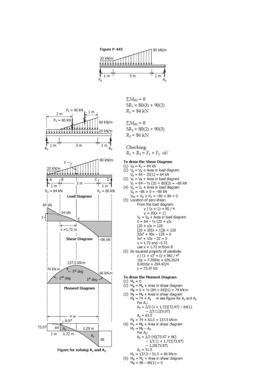
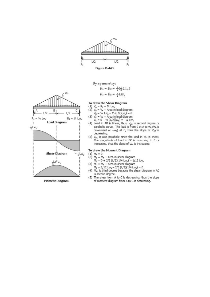
Problem 445
Beam carrying the loads shown in Fig. P-445.
Solution 445
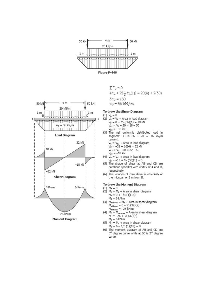
Problem 446
Beam loaded and supported as shown in Fig. P-446.
Solution 446
Finding the Load & Moment Diagrams with Given Shear
Diagram
INSTRUCTION
In the following problems, draw moment and load diagrams corresponding to the given
shear diagrams. Specify values at all change of load positions and at all points of zero
shear.
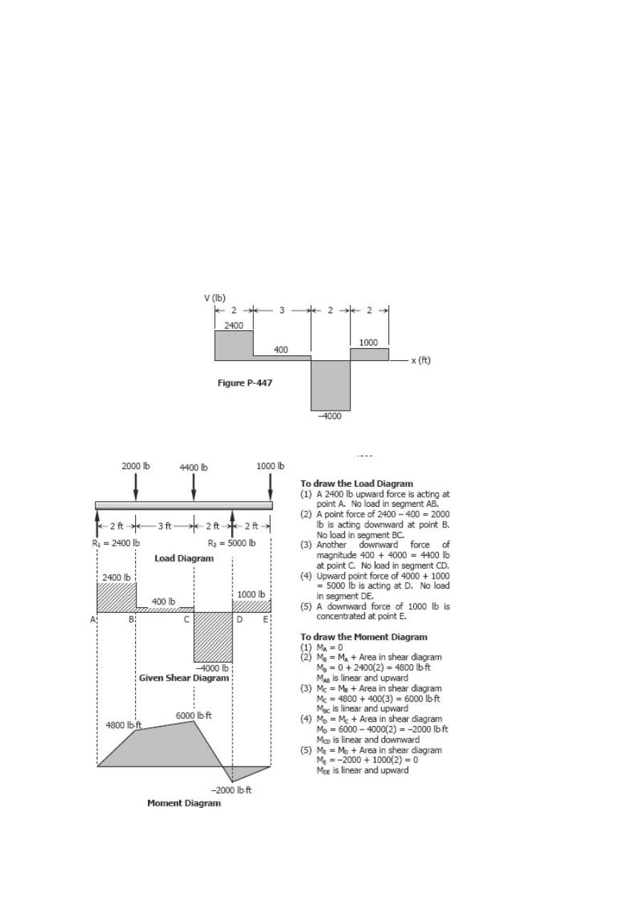
Problem 447
Shear diagram as shown in Fig. P-447.
Solution 447
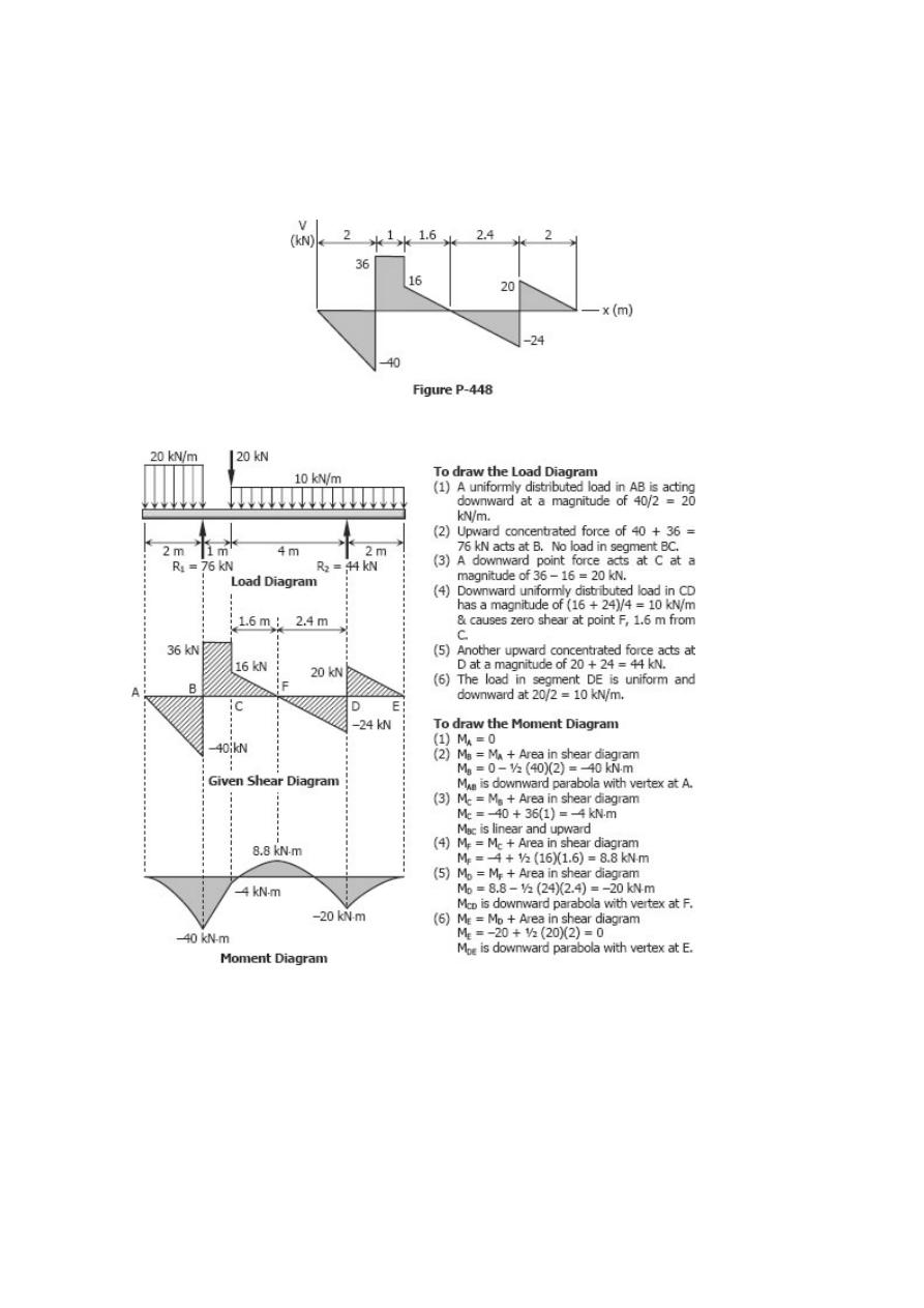
Problem 448
Shear diagram as shown in Fig. P-448.
Solution 448
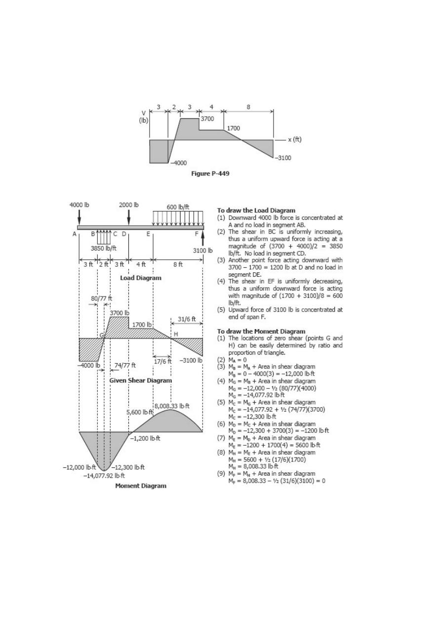
Problem 449
Shear diagram as shown in Fig. P-449.
Solution 449
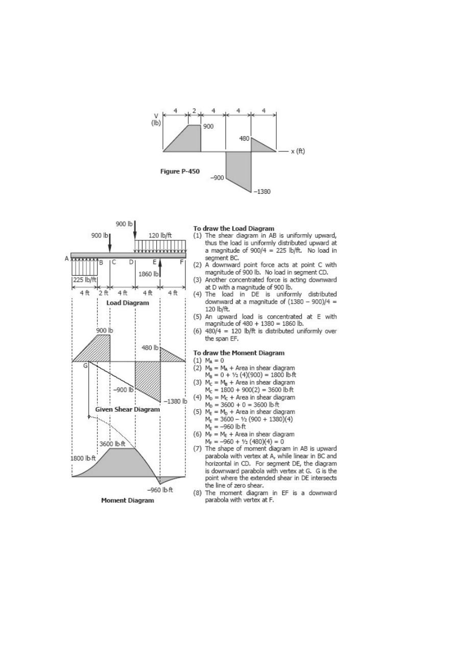
Problem 450
Shear diagram as shown in Fig. P-450.
Solution 450
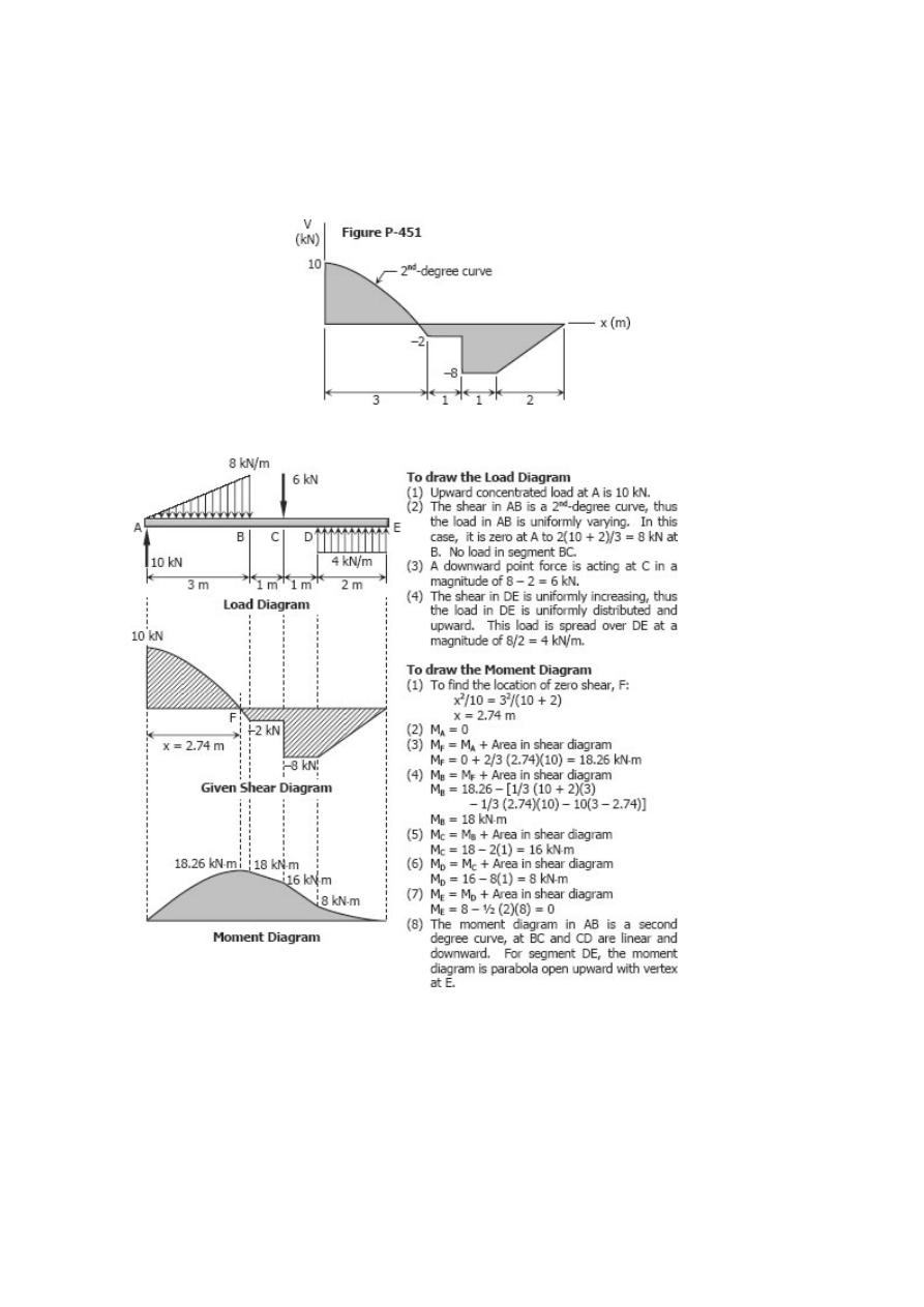
Problem 451
Shear diagram as shown in Fig. P-451.
Solution 451
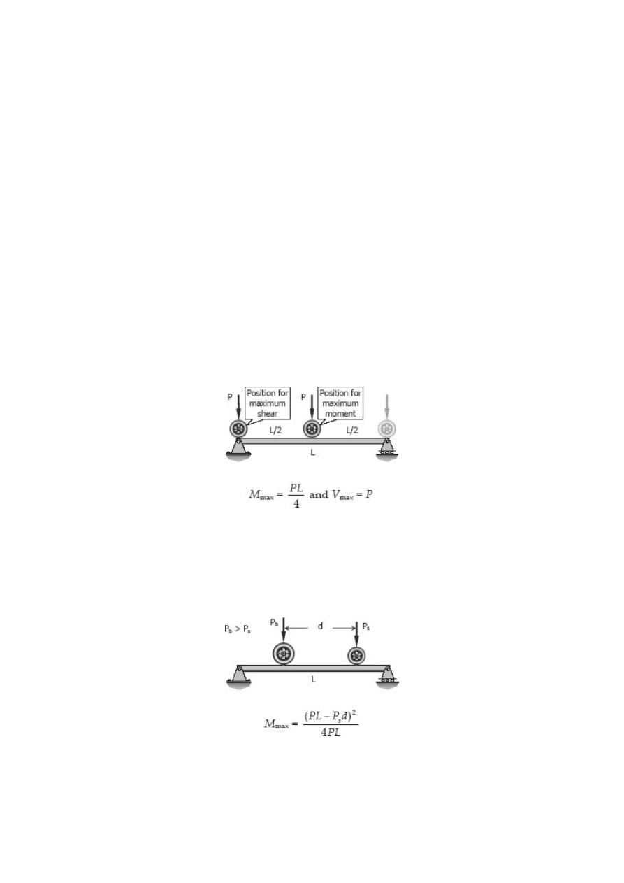
Moving Loads
From the previous section, we see that the maximum moment occurs at a point of zero
shears. For beams loaded with concentrated loads, the point of zero shears usually
occurs under a concentrated load and so the maximum moment.
Beams and girders such as in a bridge or an overhead crane are subject to moving
concentrated loads, which are at fixed distance with each other. The problem here is to
determine the moment under each load when each load is in a position to cause a
maximum moment. The largest value of these moments governs the design of the
beam.
SINGLE MOVING LOAD
For a single moving load, the maximum moment occurs when the load is at the midspan
and the maximum shear occurs when the load is very near the support (usually
assumed to lie over the support).
TWO MOVING LOADS
For two moving loads, the maximum shear occurs at the reaction when the larger load
is over that support. The maximum moment is given by
where P
s
is the smaller load, P
b
is the bigger load, and P is the total load (P = P
s
+ P
b
).
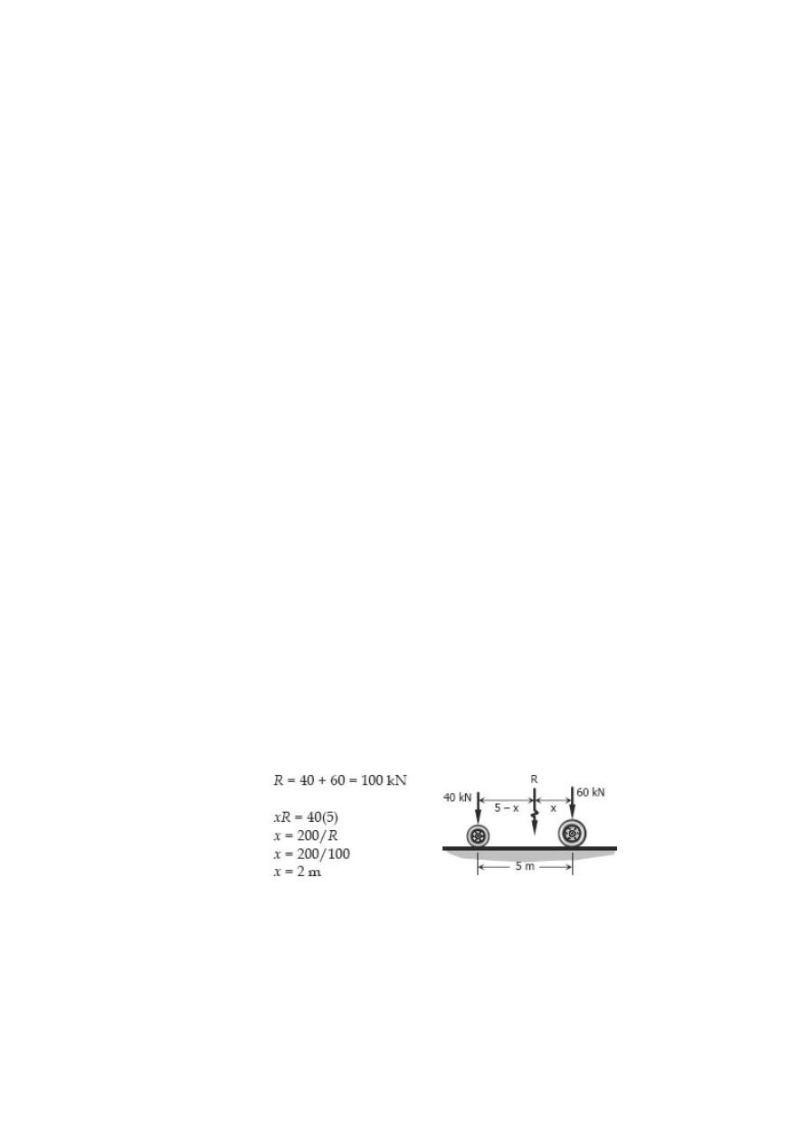
THREE OR MORE MOVING LOADS
In general, the bending moment under a particular load is a maximum when the center
of the beam is midway between that load and the resultant of all the loads then on the
span. With this rule, we compute the maximum moment under each load, and use the
biggest of the moments for the design. Usually, the biggest of these moments occurs
under the biggest load.
The maximum shear occurs at the reaction where the resultant load is nearest. Usually,
it happens if the biggest load is over that support and as many a possible of the
remaining loads are still on the span.
The maximum shear occurs at the reaction where the resultant load is nearest. Usually,
it happens if the biggest load is over that support and as many a possible of the
remaining loads are still on the span. In determining the largest moment and shear, it is
sometimes necessary to check the condition when the bigger loads are on the span and
the rest of the smaller loads are outside.
Solved Problems in Moving Loads
Problem 453
A truck with axle loads of 40 kN and 60 kN on a wheel base of 5 m rolls across a 10-m
span. Compute the maximum bending moment and the maximum shearing force.
Solution 453
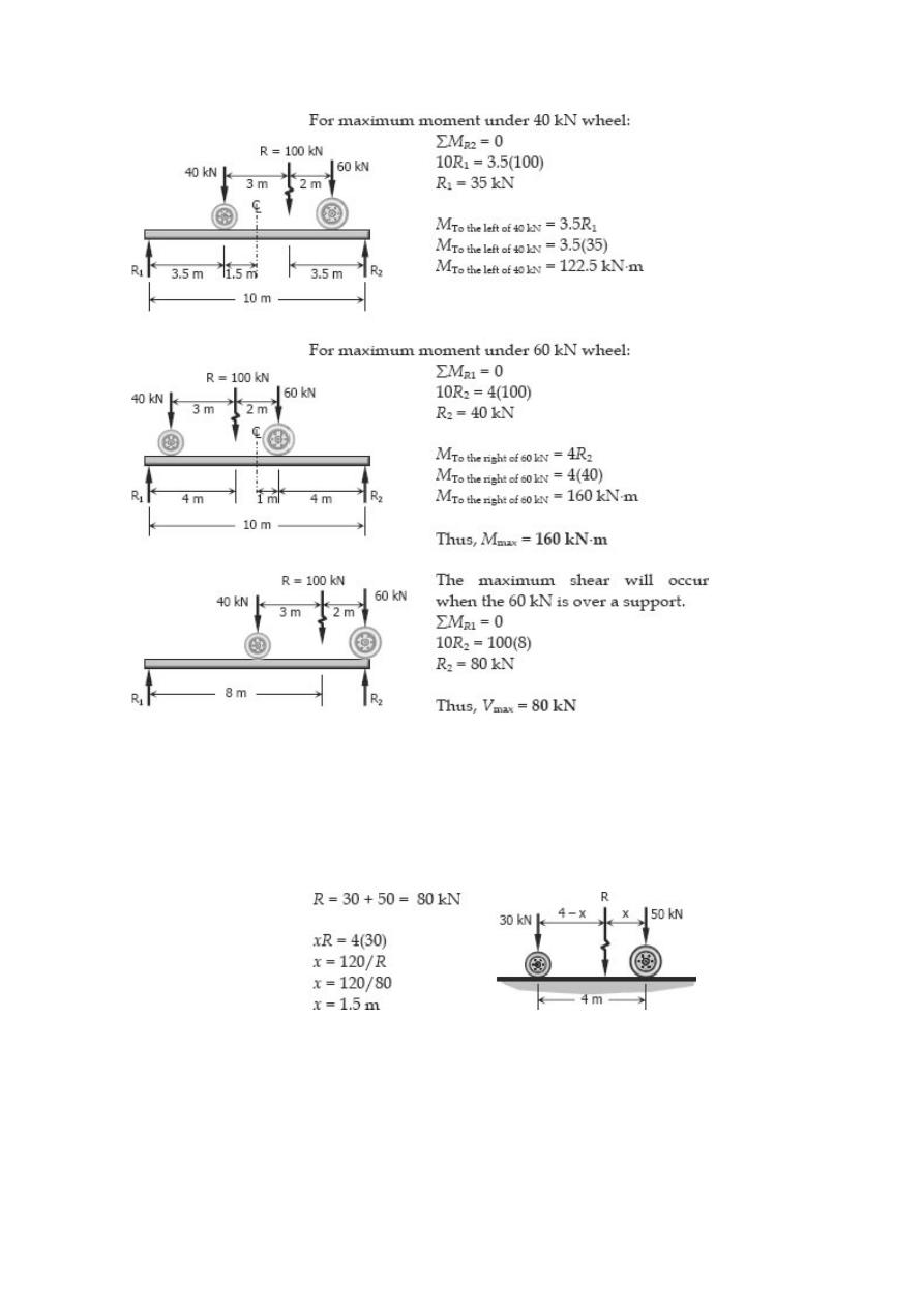
Problem 454
Repeat Prob. 453 using axle loads of 30 kN and 50 kN on a wheel base of 4 m crossing
an 8-m span.
Solution 454
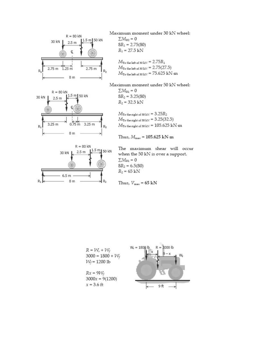
Problem 455
A tractor weighing 3000 lb, with a wheel base of 9 ft, carries 1800 lb of its load on the
rear wheels. Compute the maximum moment and maximum shear when crossing a 14
ft-span.
Solution 455
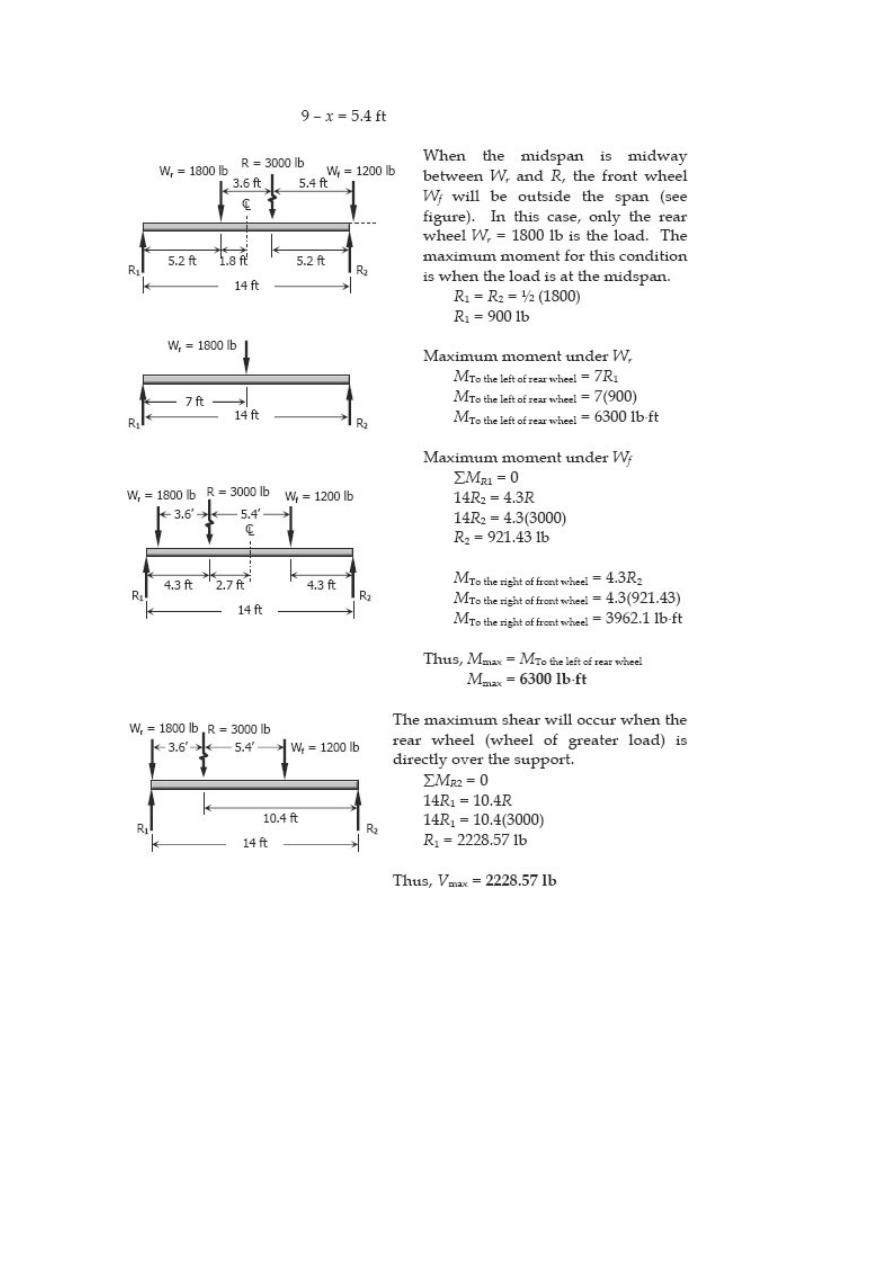
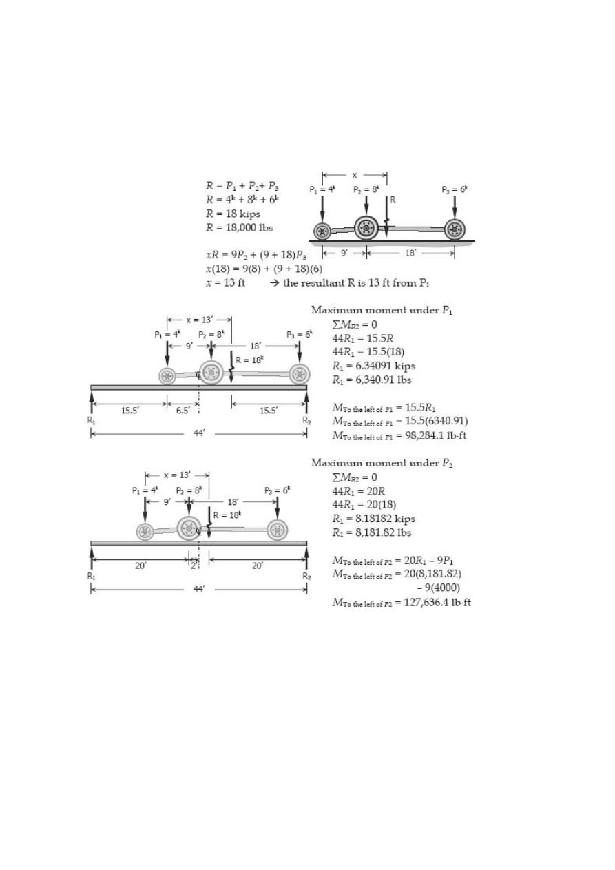
Problem 456
Three wheel loads roll as a unit across a 44-ft span. The loads are P
1
= 4000 lb and P
2
=
8000 lb separated by 9 ft, and P
3
= 6000 lb at 18 ft from P
2
. Determine the maximum
moment and maximum shear in the simply supported span.
Solution 456
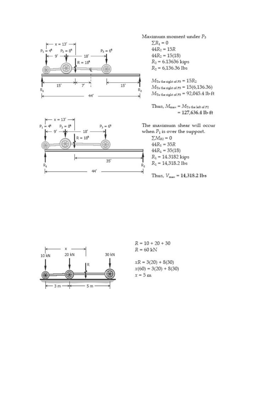
Problem 457
A truck and trailer combination crossing a 12-m span has axle loads of 10, 20, and 30
kN separated respectively by distances of 3 and 5 m. Compute the maximum moment
and maximum shear developed in the span.
Solution 457
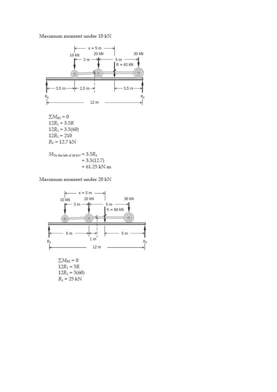
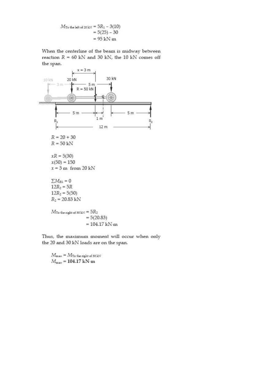
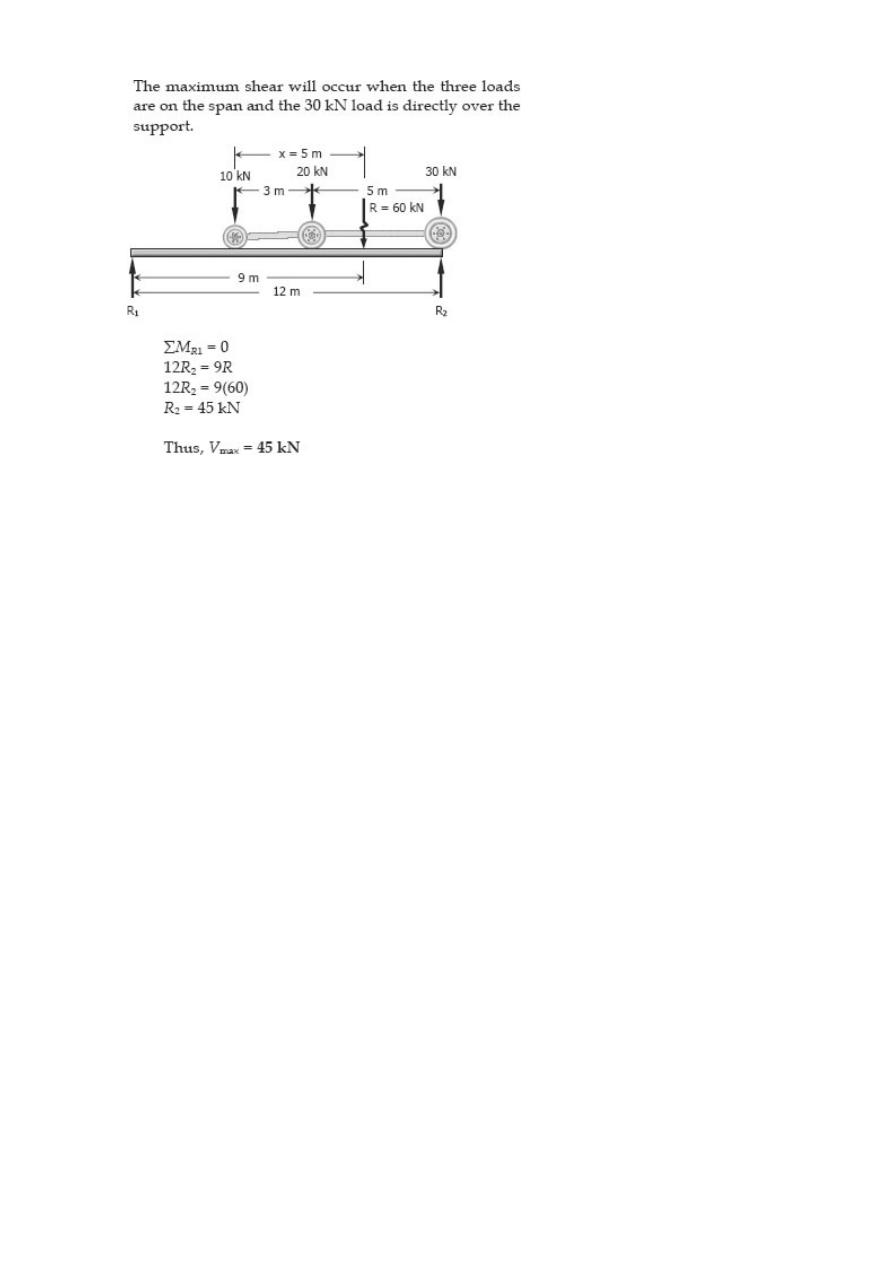
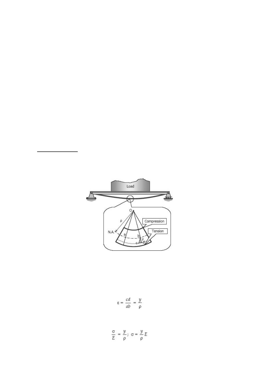
Stresses in Beams
Forces and couples acting on the beam cause bending (flexural stresses) and shearing
stresses on any cross section of the beam and deflection perpendicular to the
longitudinal axis of the beam. If couples are applied to the ends of the beam and no
forces act on it, the bending is said to be pure bending. If forces produce the bending,
the bending is called ordinary bending.
ASSUMPTIONS
In using the following formulas for flexural and shearing stresses, it is assumed that a
plane section of the beam normal to its longitudinal axis prior to loading remains plane
after the forces and couples have been applied, and that the beam is initially straight
and of uniform cross section and that the moduli of elasticity in tension and
compression are equal.
Flexure Formula
Stresses caused by the bending moment are known as flexural or bending stresses.
Consider a beam to be loaded as shown.
Consider a fiber at a distance y from the neutral axis, because of the beam’s curvature,
as the effect of bending moment, the fiber is stretched by an amount of cd. Since the
curvature of the beam is very small, bcd and Oba are considered as similar triangles.
The strain on this fiber is
By Hooke’s law, ε = σ / E, then
which means that the stress is proportional to the distance y from the neutral axis.
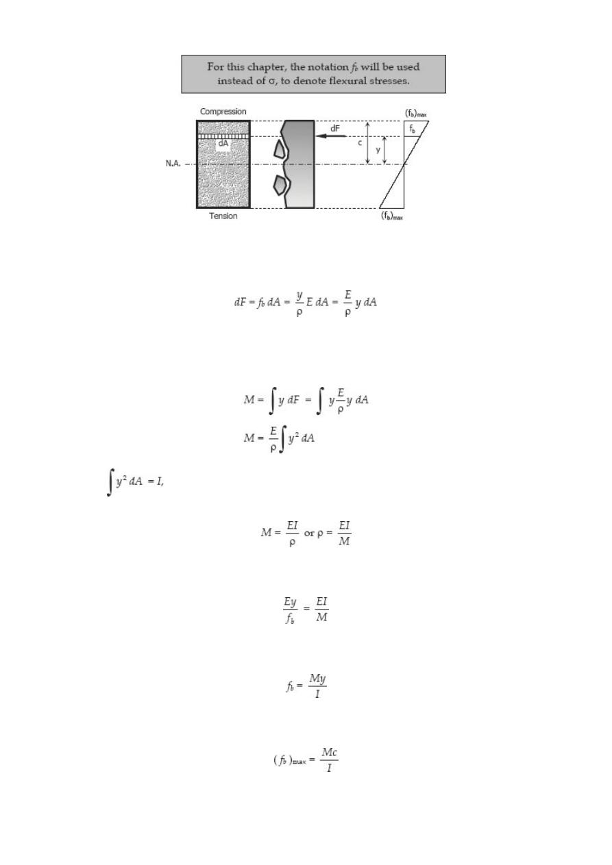
Considering a differential area dA at a distance y from N.A., the force acting over the
area is
The resultant of all the elemental moment about N.A. must be equal to the bending
moment on the section.
but
then
substituting ρ = Ey / f
b
then
and
The bending stress due to beams curvature is
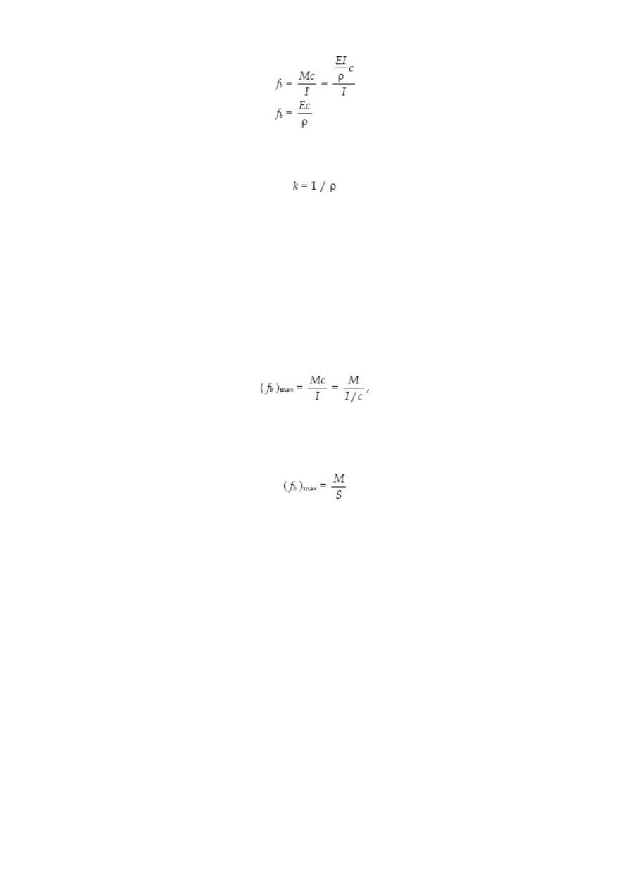
The beam curvature is:
where ρ is the radius of curvature of the beam in mm (in), M is the bending moment in
N·mm (lb·in), f
b
is the flexural stress in MPa (psi), I is the centroidal moment of inertia
in mm
4
(in
4
), and c is the distance from the neutral axis to the outermost fiber in mm
(in).
SECTION MODULUS
In the formula
the ratio I/c is called the section modulus and is usually denoted by S with units of mm
3
(in
3
). The maximum bending stress may then be written as
This form is convenient because the values of S are available in handbooks for a wide
range of standard structural shapes.
Solved Problems in Flexure Formula
Problem 503
A cantilever beam, 50 mm wide by 150 mm high and 6 m long, carries a load that
varies uniformly from zero at the free end to 1000 N/m at the wall. (a) Compute the
magnitude and location of the maximum flexural stress. (b) Determine the type and
magnitude of the stress in a fiber 20 mm from the top of the beam at a section 2 m
from the free end.
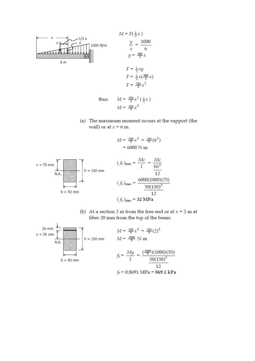
Solution 503
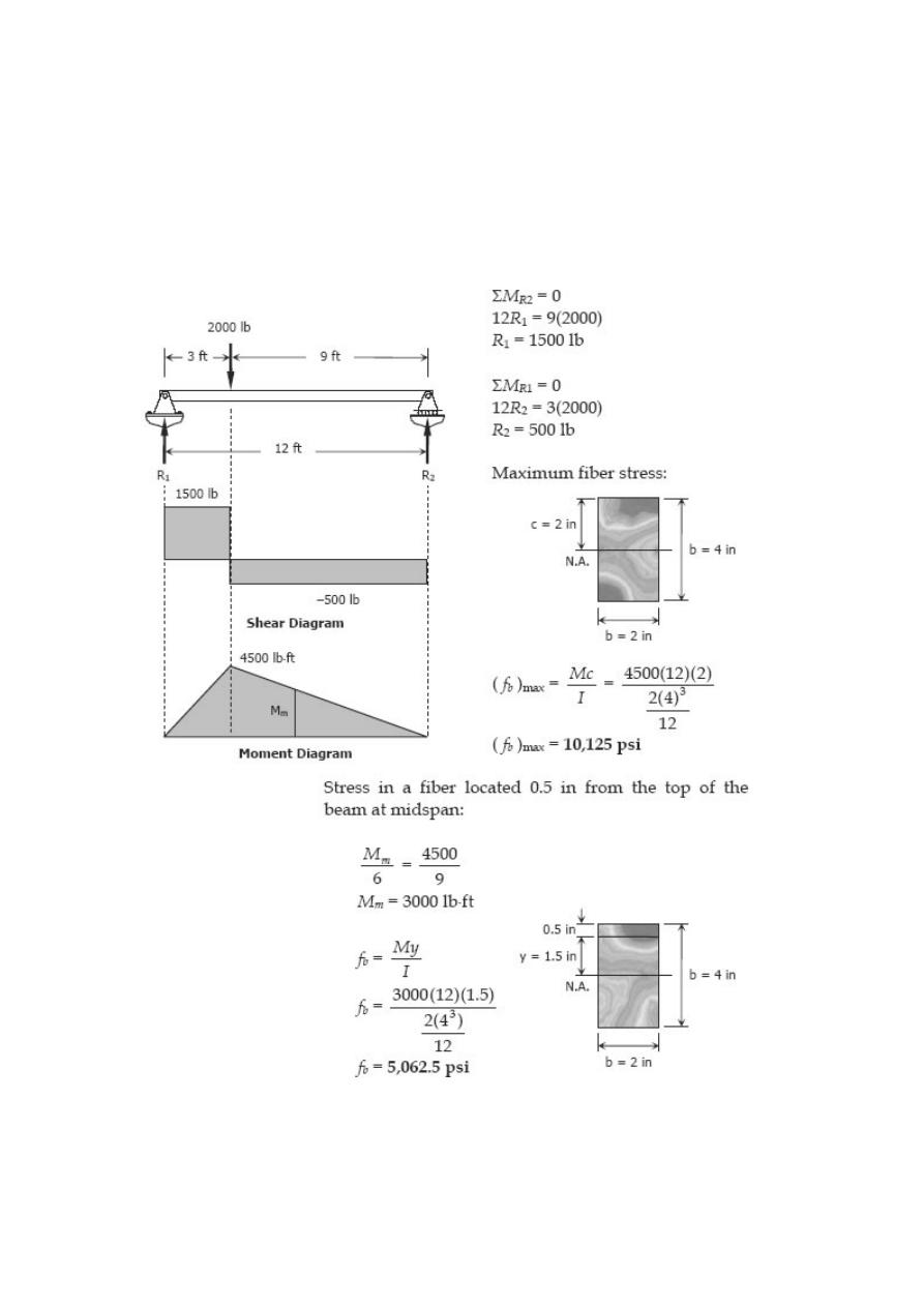
Problem 504
A simply supported beam, 2 in wide by 4 in high and 12 ft long is subjected to a
concentrated load of 2000 lb at a point 3 ft from one of the supports. Determine the
maximum fiber stress and the stress in a fiber located 0.5 in from the top of the beam
at midspan.
Solution 504
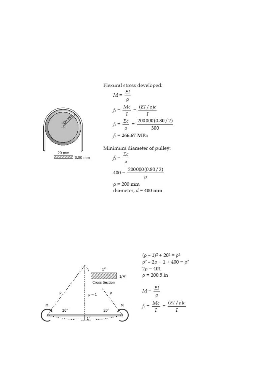
Problem 505
A high strength steel band saw, 20 mm wide by 0.80 mm thick, runs over pulleys 600
mm in diameter. What maximum flexural stress is developed? What minimum diameter
pulleys can be used without exceeding a flexural stress of 400 MPa? Assume E = 200
GPa.
Solution 505
Problem 506
A flat steel bar, 1 inch wide by ¼ inch thick and 40 inches long, is bent by couples
applied at the ends so that the midpoint deflection is 1.0 inch. Compute the stress in
the bar and the magnitude of the couples. Use E = 29 × 10
6
psi.
Solution 506
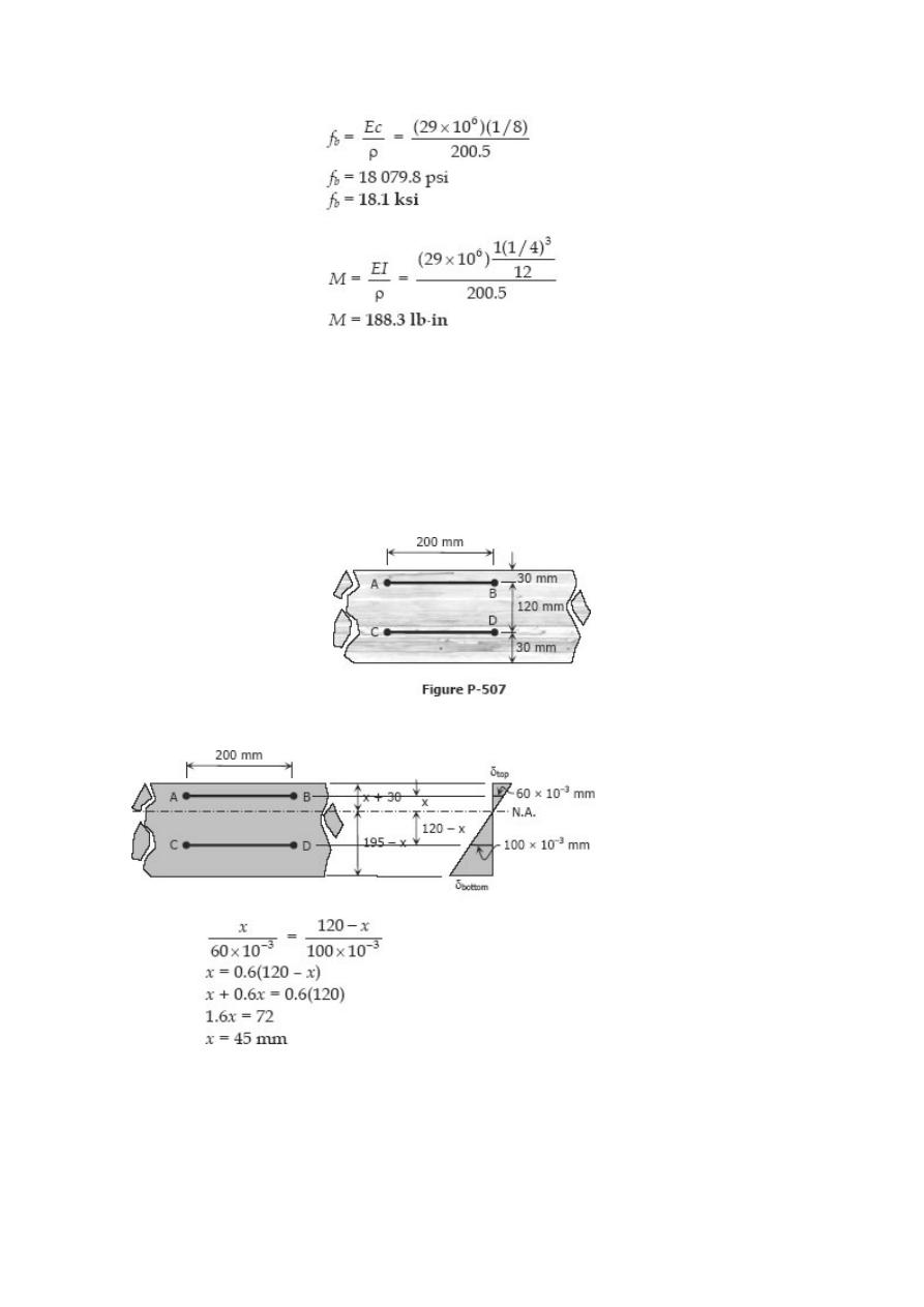
Problem 507
In a laboratory test of a beam loaded by end couples, the fibers at layer AB in Fig. P-
507 are found to increase 60 × 10
–3
mm whereas those at CD decrease 100 × 10
–3
mm
in the 200-mm-gage length. Using E = 70 GPa, determine the flexural stress in the top
and bottom fibers.
Solution 507
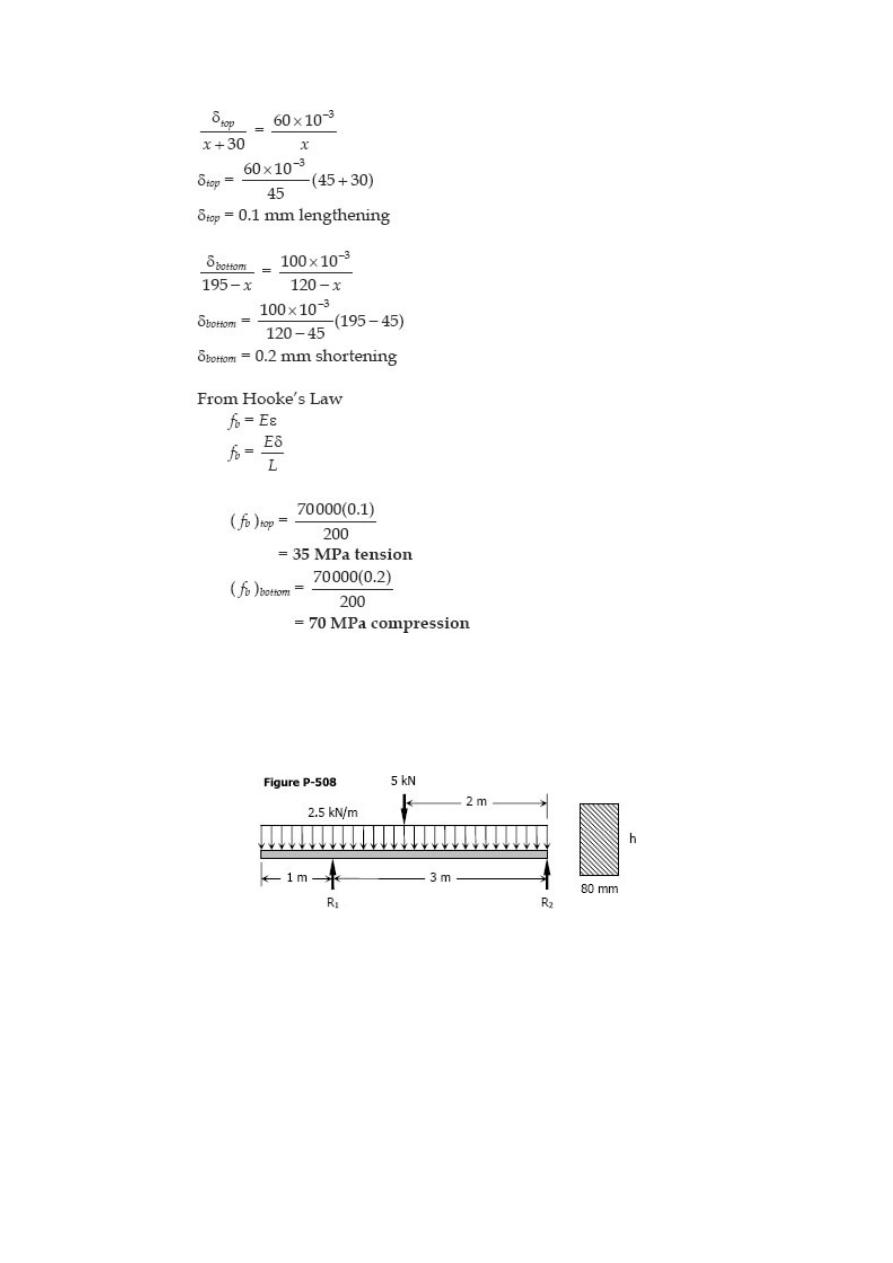
Problem 508
Determine the minimum height h of the beam shown in Fig. P-508 if the flexural stress
is not to exceed 20 MPa.
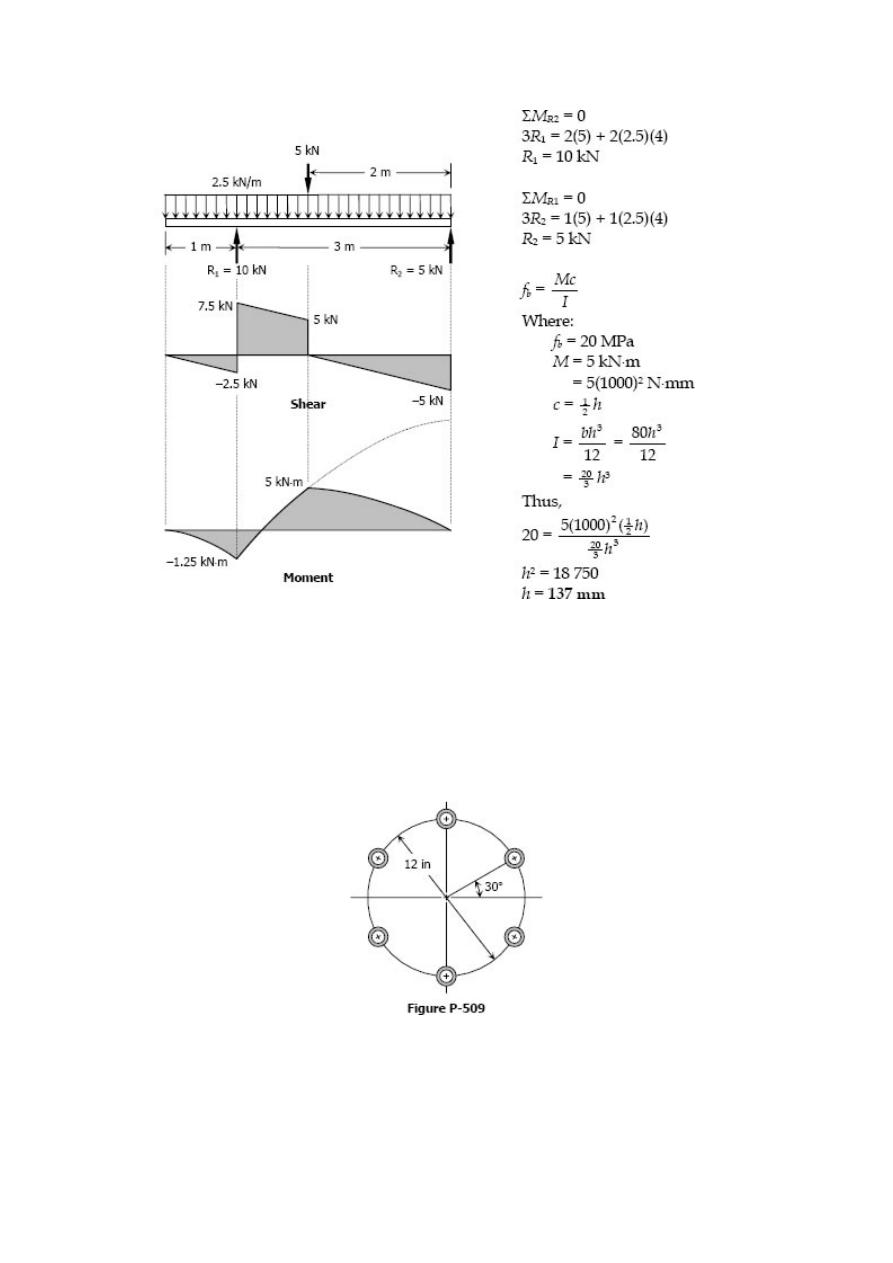
Solution 508
Problem 509
A section used in aircraft is constructed of tubes connected by thin webs as shown in
Fig. P-509. Each tube has a cross-sectional area of 0.20 in2. If the average stress in the
tubes is no to exceed 10 ksi, determine the total uniformly distributed load that can be
supported in a simple span 12 ft long. Neglect the effect of the webs.
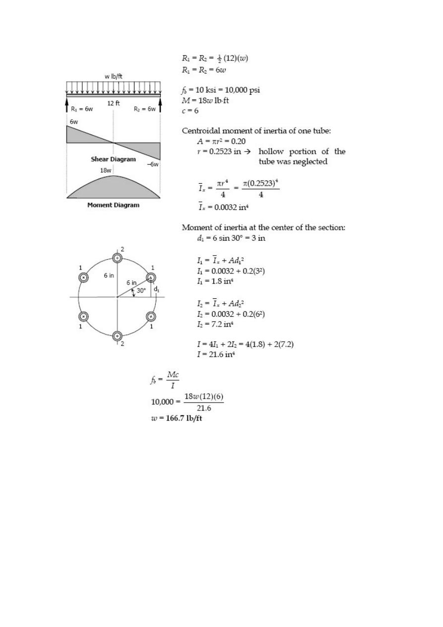
Solution 509
Problem 510
A 50-mm diameter bar is used as a simply supported beam 3 m long. Determine the
largest uniformly distributed load that can be applied over the right two-thirds of the
beam if the flexural stress is limited to 50 MPa.
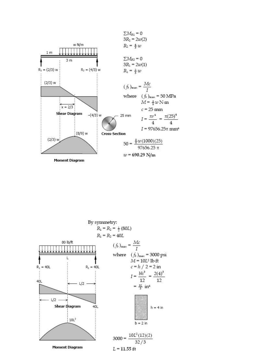
Solution 510
Problem 511
A simply supported rectangular beam, 2 in wide by 4 in deep, carries a uniformly
distributed load of 80 lb/ft over its entire length. What is the maximum length of the
beam if the flexural stress is limited to 3000 psi?
Solution 511
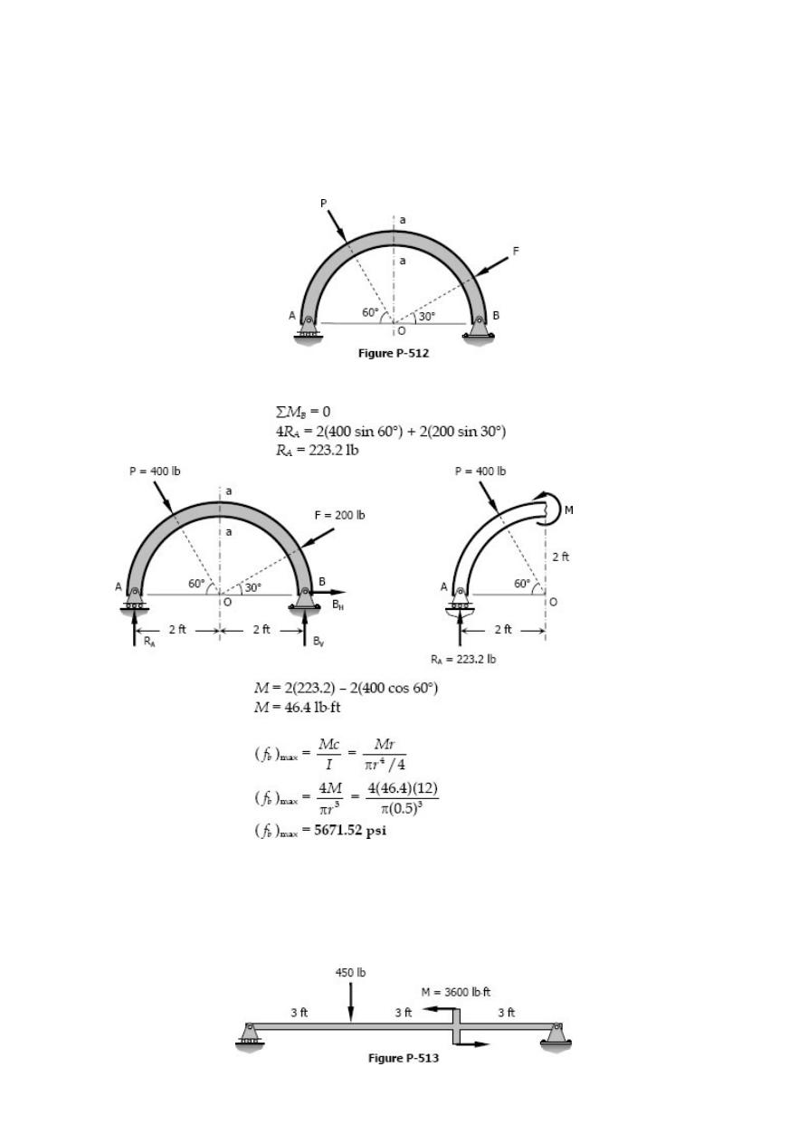
Problem 512
The circular bar 1 inch in diameter shown in Fig. P-512 is bent into a semicircle with a
mean radius of 2 ft. If P = 400 lb and F = 200 lb, compute the maximum flexural stress
developed in section a-a. Neglect the deformation of the bar.
Solution 512
Problem 513
A rectangular steel beam, 2 in wide by 3 in deep, is loaded as shown in Fig. P-513.
Determine the magnitude and the location of the maximum flexural stress.
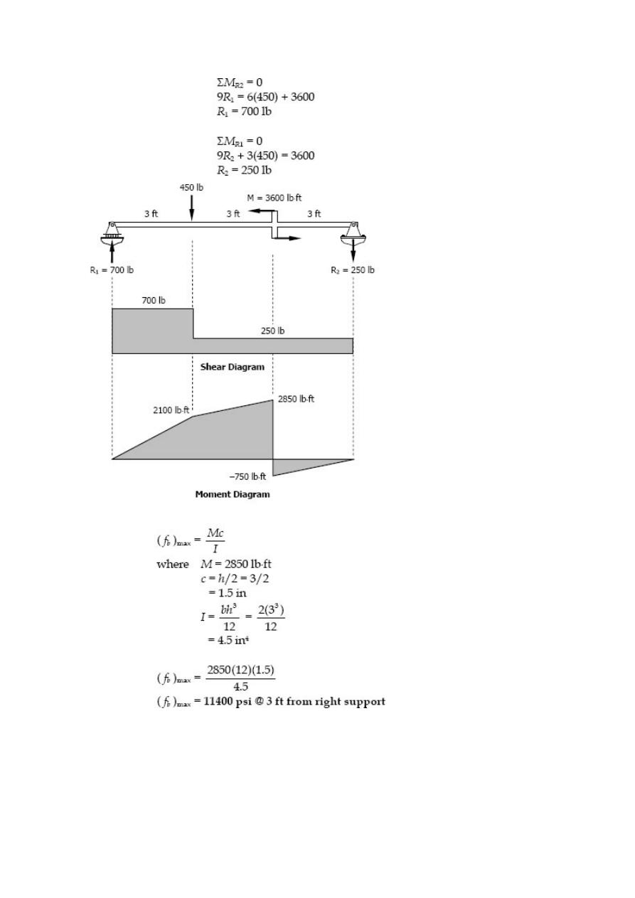
Solution 513
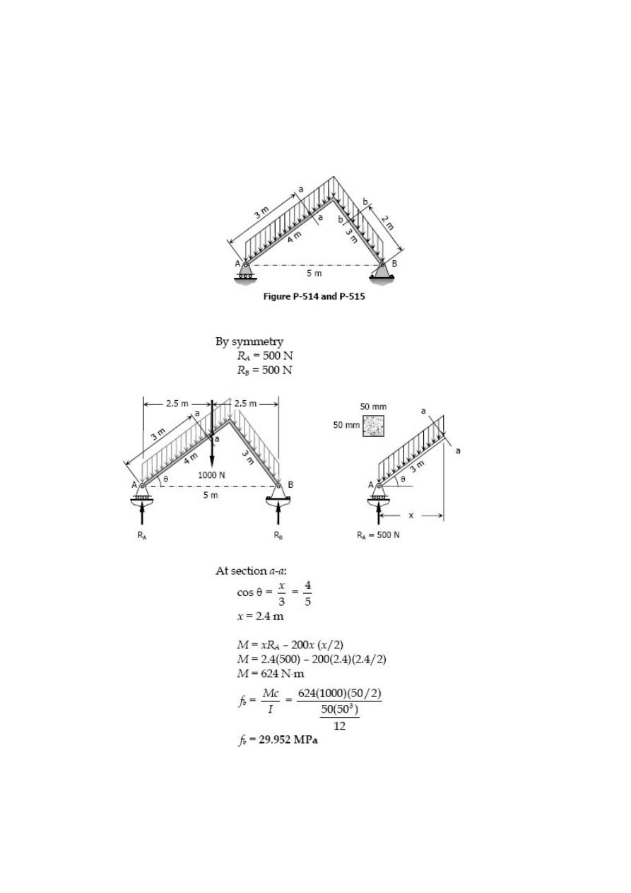
Problem 514
The right-angled frame shown in Fig. P-514 carries a uniformly distributed loading
equivalent to 200 N for each horizontal projected meter of the frame; that is, the total
load is 1000 N. Compute the maximum flexural stress at section a-a if the cross-section
is 50 mm square.
Solution 514
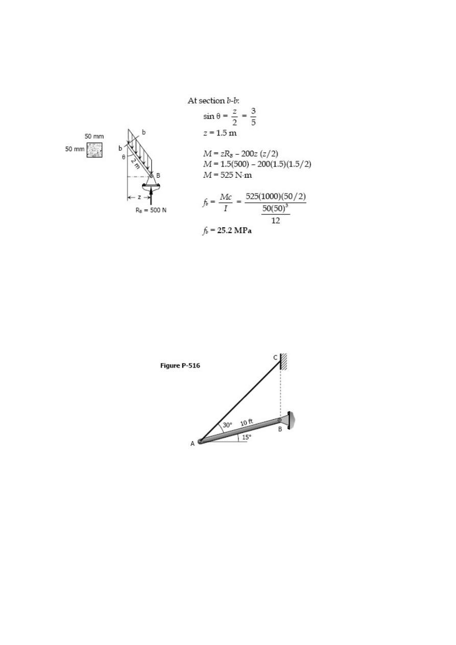
Problem 515
Repeat Prob. 524 to find the maximum flexural stress at section b-b.
Solution 515
Problem 516
A timber beam AB, 6 in wide by 10 in deep and 10 ft long, is supported by a guy wire
AC in the position shown in Fig. P-516. The beam carries a load, including its own
weight, of 500 lb for each foot of its length. Compute the maximum flexural stress at
the middle of the beam.
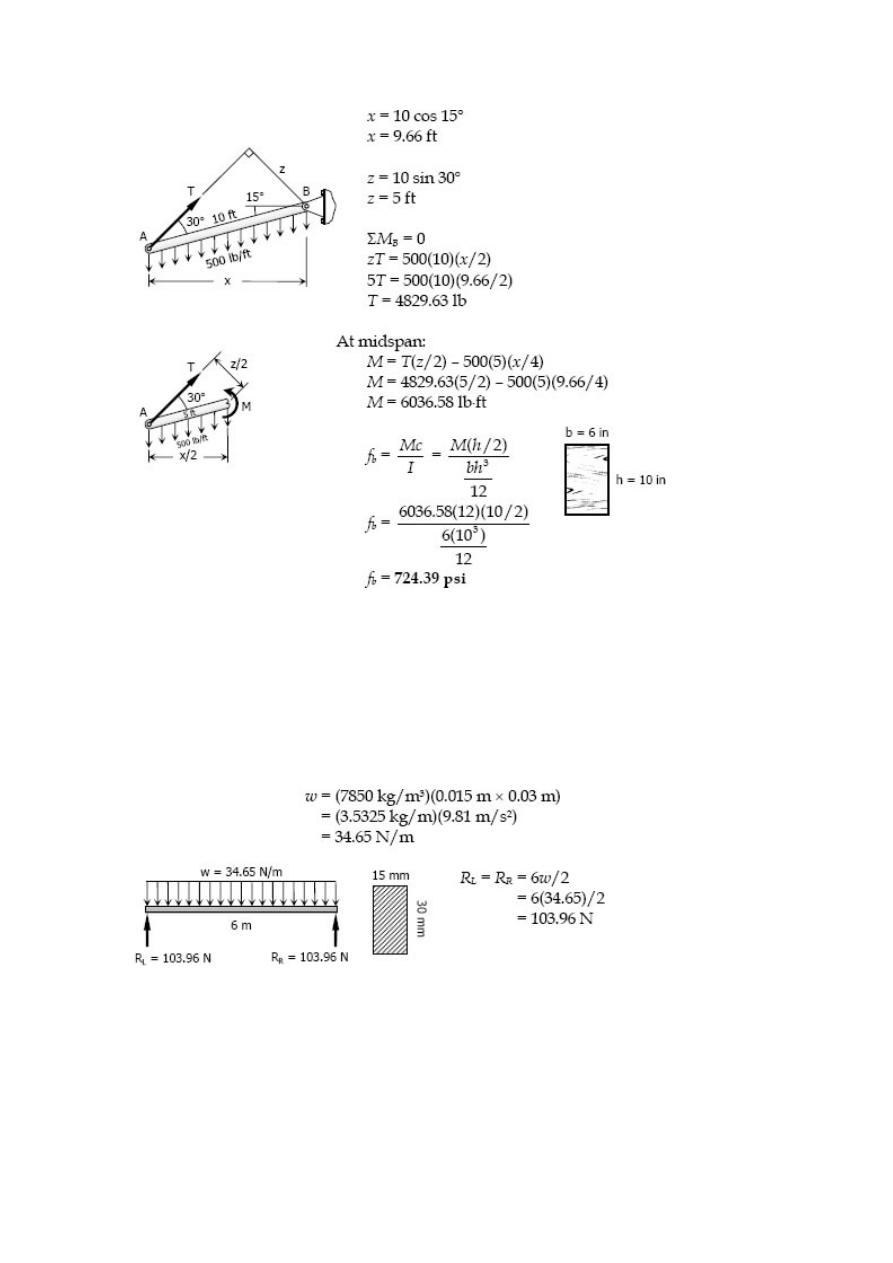
Solution 516
Problem 517
A rectangular steel bar, 15 mm wide by 30 mm high and 6 m long, is simply supported
at its ends. If the density of steel is 7850 kg/m
3
, determine the maximum bending
stress caused by the weight of the bar.
Solution 517
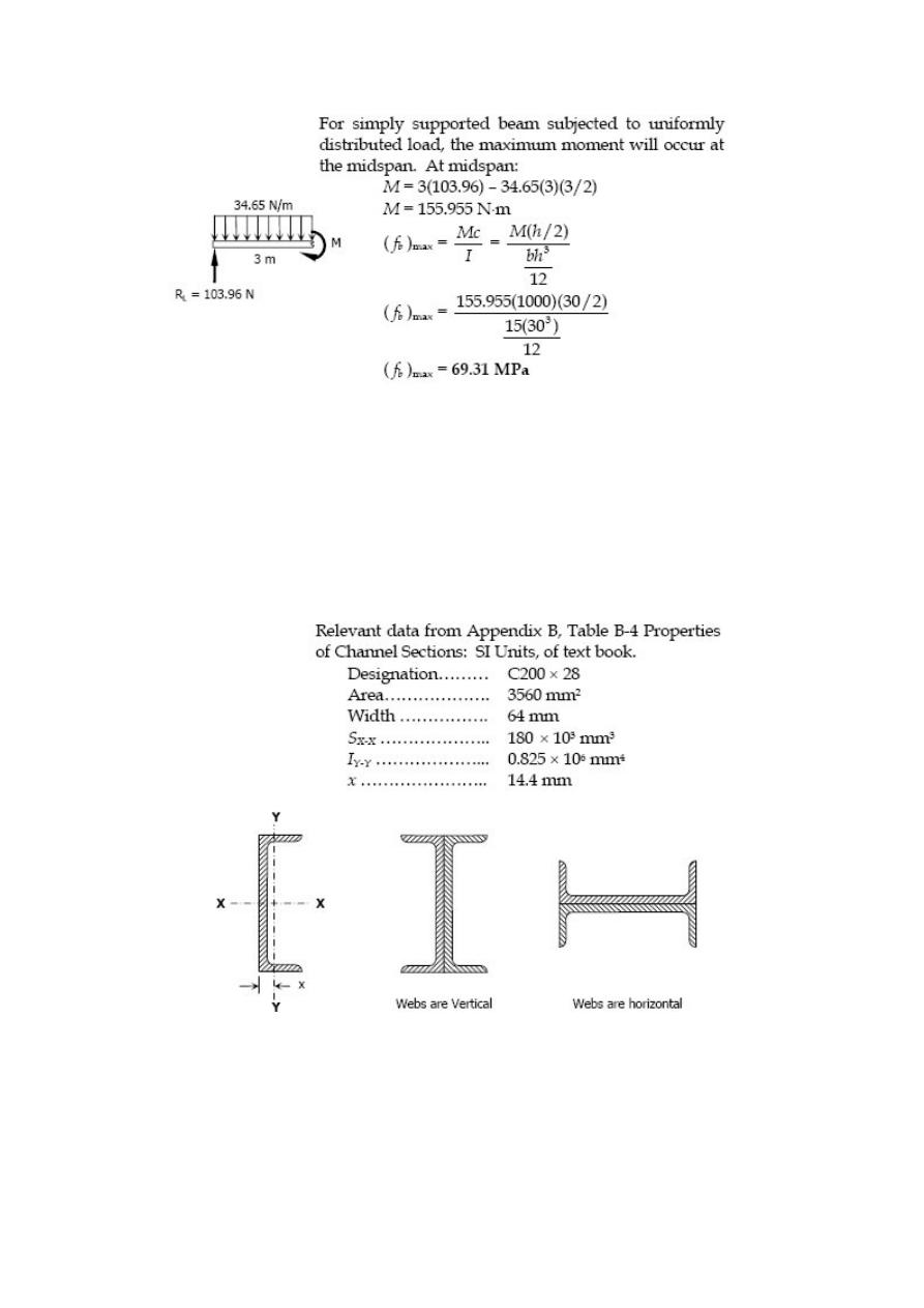
Problem 518
A cantilever beam 4 m long is composed of two C200 × 28 channels riveted back to
back. What uniformly distributed load can be carried, in addition to the weight of the
beam, without exceeding a flexural stress of 120 MPa if (a) the webs are vertical and
(b) the webs are horizontal? Refer to Appendix B of text book for channel properties.
Solution 518
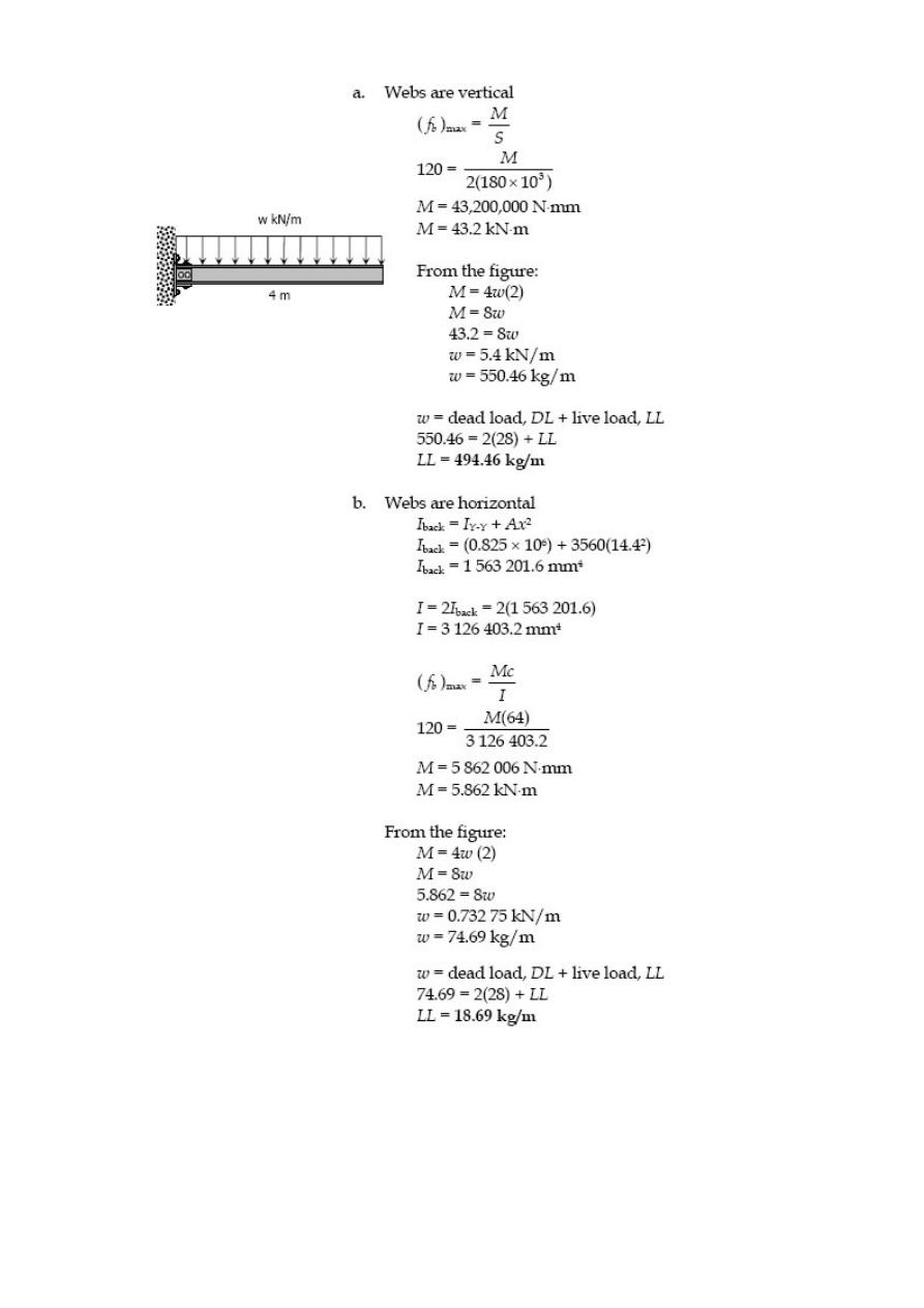
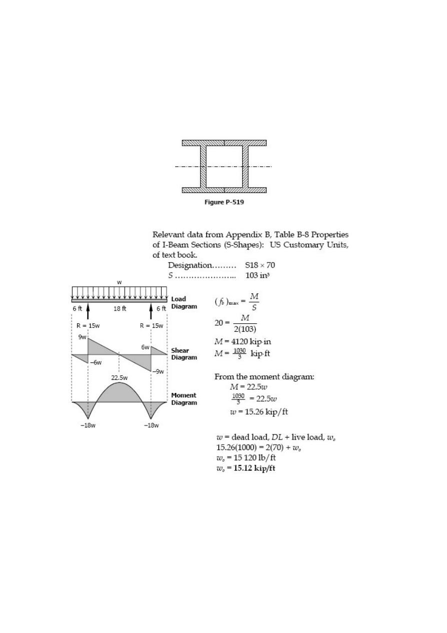
Problem 519
A 30-ft beam, simply supported at 6 ft from either end carries a uniformly distributed
load of intensity w
o
over its entire length. The beam is made by welding two S18 × 70
(see appendix B of text book) sections along their flanges to form the section shown in
Fig. P-519. Calculate the maximum value of wo if the flexural stress is limited to 20 ksi.
Be sure to include the weight of the beam.
Solution 519
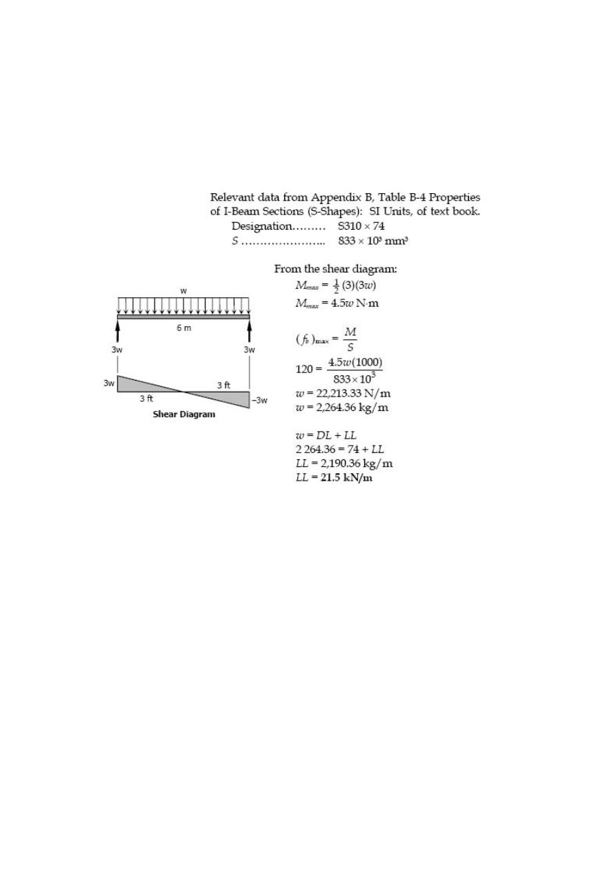
Problem 520
A beam with an S310 × 74 section (see Appendix B of textbook) is used as a simply
supported beam 6 m long. Find the maximum uniformly distributed load that can be
applied over the entire length of the beam, in addition to the weight of the beam, if the
flexural stress is not to exceed 120 MPa.
Solution 520
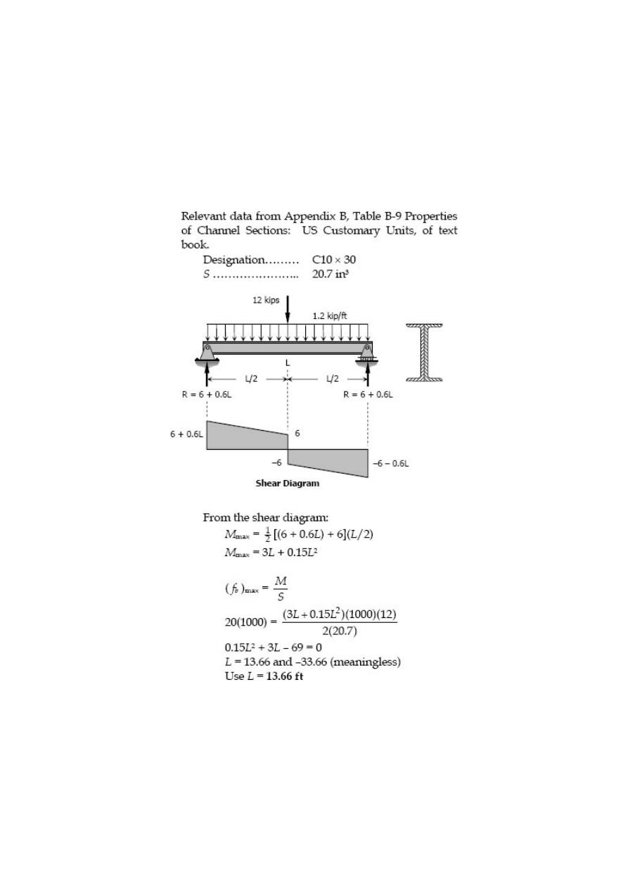
Problem 521
A beam made by bolting two C10 × 30 channels back to back, is simply supported at its
ends. The beam supports a central concentrated load of 12 kips and a uniformly
distributed load of 1200 lb/ft, including the weight of the beam. Compute the maximum
length of the beam if the flexural stress is not to exceed 20 ksi.
Solution 521
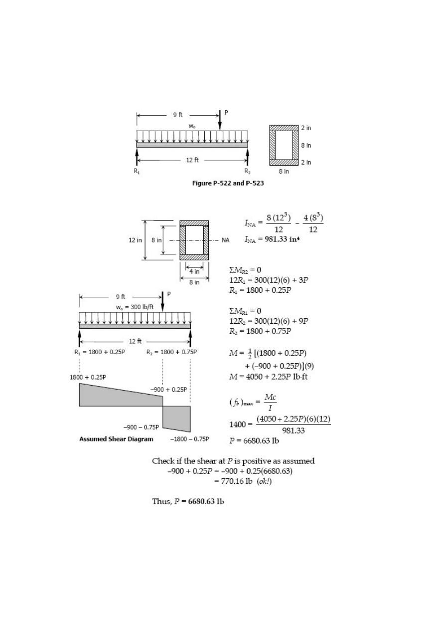
Problem 522
A box beam is composed of four planks, each 2 inches by 8 inches, securely spiked
together to form the section shown in Fig. P-522. Show that I
NA
= 981.3 in
4
. If w
o
= 300
lb/ft, find P to cause a maximum flexural stress of 1400 psi.
Solution 522
Problem 523
Solve Prob. 522 if w
o
= 600 lb/ft.
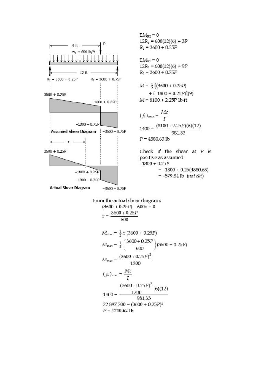
Solution 523
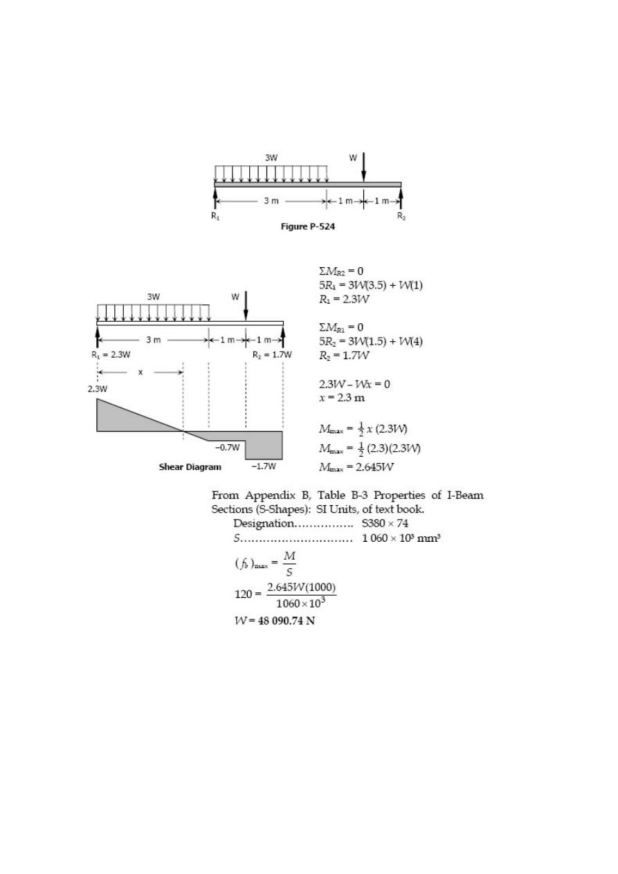
Problem 524
A beam with an S380 × 74 section carries a total uniformly distributed load of 3W
and a concentrated load W, as shown in Fig. P-524. Determine W if the
flexural stress is limited to 120 MPa.
Solution 524
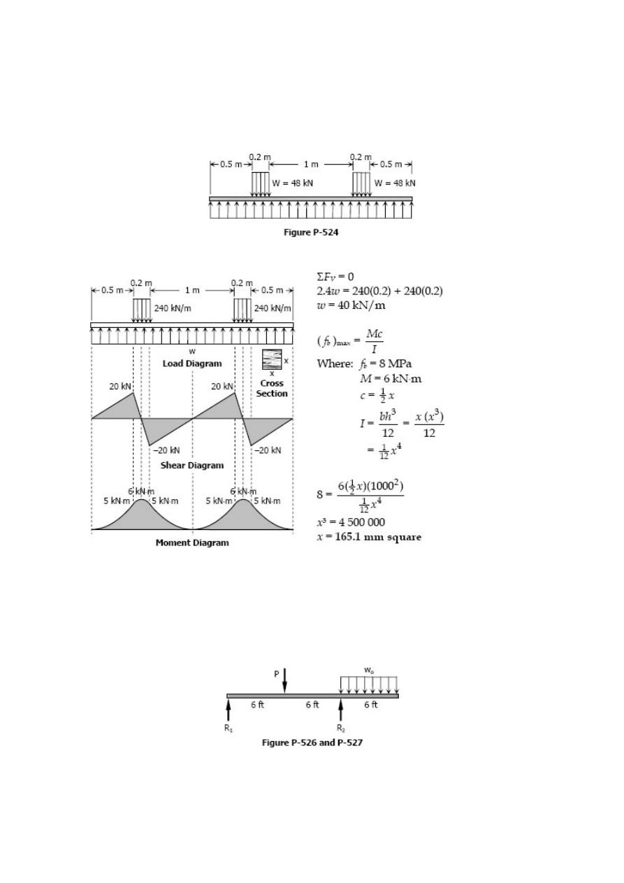
Problem 525
A square timber beam used as a railroad tie is supported by a uniformly distributed
loads and carries two uniformly distributed loads each totaling 48 kN as shown in Fig. P-
525. Determine the size of the section if the maximum stress is limited to 8 MPa.
Solution 525
Problem 526
A wood beam 6 in wide by 12 in deep is loaded as shown in Fig. P-526. If the maximum
flexural stress is 1200 psi, find the maximum values of w
o
and P which can be applied
simultaneously?
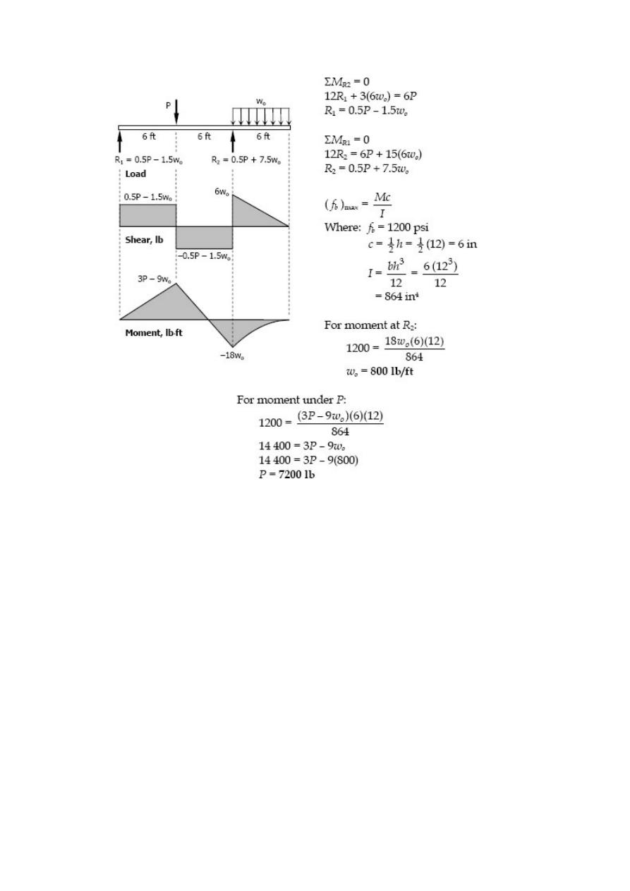
Solution 526
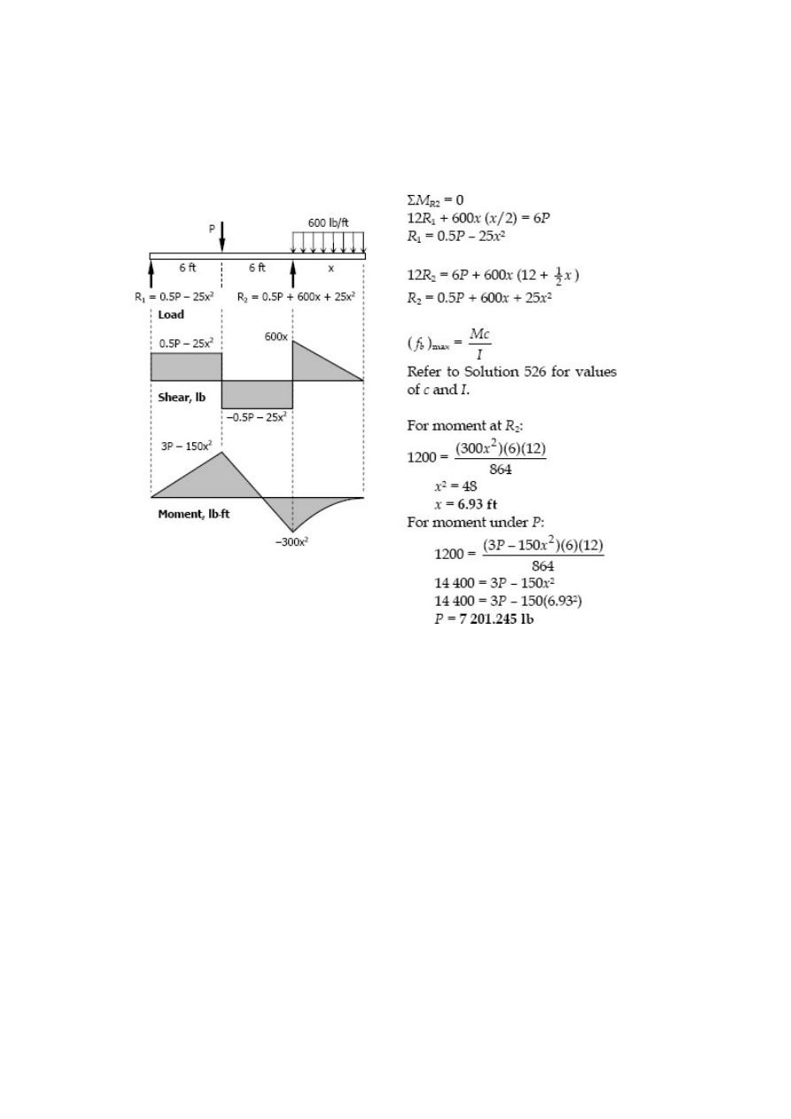
Problem 527
In Prob. 526, if the load on the overhang is 600 lb/ft and the overhang is x ft long, find
the maximum values of P and x that can be used simultaneously.
Solution 527
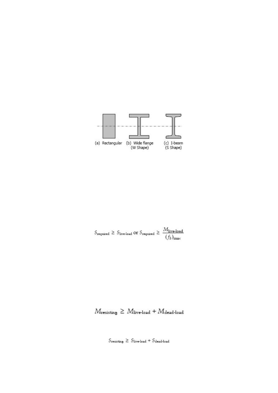
Economic Sections
From the flexure formula f
b
= My / I, it can be seen that the bending stress at the
neutral axis, where y = 0, is zero and increases linearly outwards. This means that for a
rectangular or circular section a large portion of the cross section near the middle
section is understressed.
For steel beams or composite beams, instead of adopting the rectangular shape, the
area may be arranged so as to give more area on the outer fiber and maintaining the
same overall depth, and saving a lot of weight.
When using a wide flange or I-beam section for long beams, the compression flanges
tend to buckle horizontally sidewise. This buckling is a column effect, which may be
prevented by providing lateral support such as a floor system so that the full allowable
stresses may be used, otherwise the stress should be reduced. The reduction of stresses
for these beams will be discussed in steel design. In selecting a structural section to be
used as a beam, the resisting moment must be equal or greater than the applied
bending moment. Note: ( f
b
)
max
= M/S.
The equation above indicates that the required section modulus of the beam must be
equal or greater than the ratio of bending moment to the maximum allowable stress. A
check that includes the weight of the selected beam is necessary to complete the
calculation. In checking, the beams resisting moment must be equal or greater than the
sum of the live-load moment caused by the applied loads and the dead-load moment
caused by dead weight of the beam.
Dividing both sides of the above equation by ( f
b
)
max
, we obtain the checking equation
Assume that the beams in the following problems are properly braced against lateral
deflection. Be sure to include the weight of the beam itself.
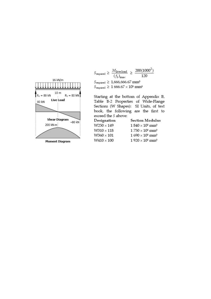
Solved Problems in Economic Sections
Problem 529
A 10-m beam simply supported at the ends carries a uniformly distributed load of 16
kN/m over its entire length. What is the lightest W shape beam that will not exceed a
flexural stress of 120 MPa? What is the actual maximum stress in the beam selected?
Solution 529
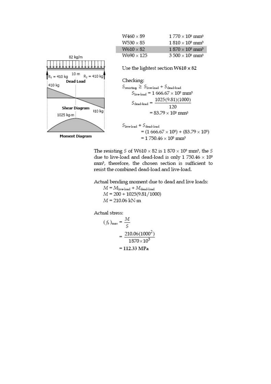
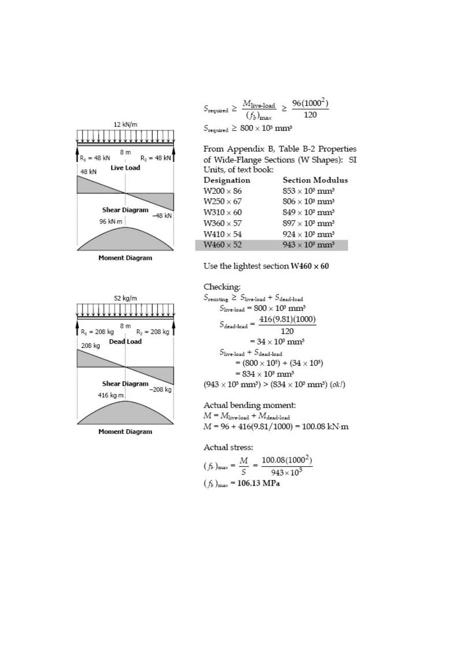
Problem 530
Repeat Prob. 529 if the distributed load is 12 kN/m and the length of the beam is 8 m.
Solution 530
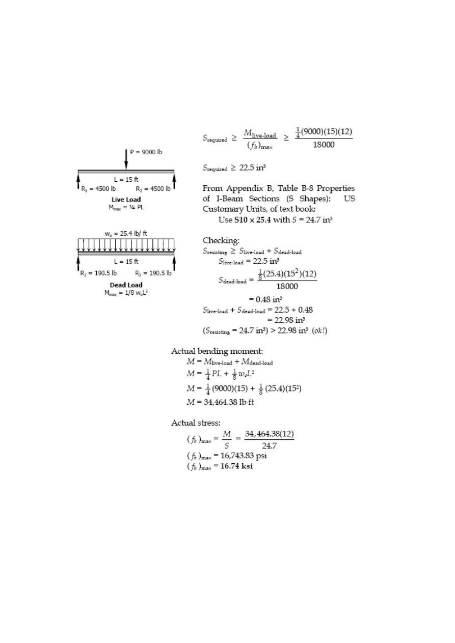
Problem 531
A 15-ft beam simply supported at the ends carries a concentrated load of 9000 lb at
midspan. Select the lightest S section that can be employed using an allowable stress of
18 ksi. What is the actual maximum stress in the beam selected?
Solution 531
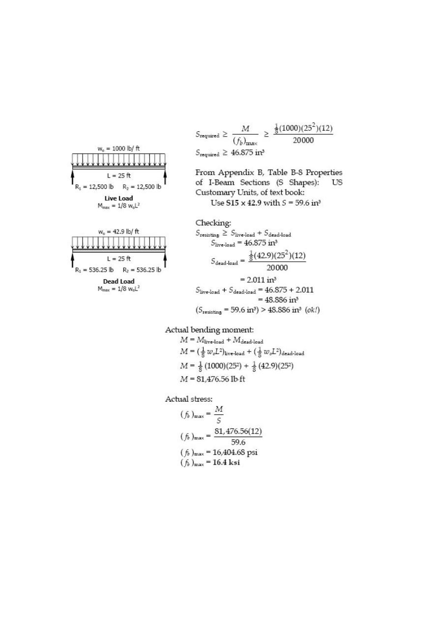
Problem 532
A beam simply supported at the ends of a 25-ft span carries a uniformly distributed load
of 1000 lb/ft over its entire length. Select the lightest S section that can be used if the
allowable stress is 20 ksi. What is the actual maximum stress in the beam selected?
Solution 532
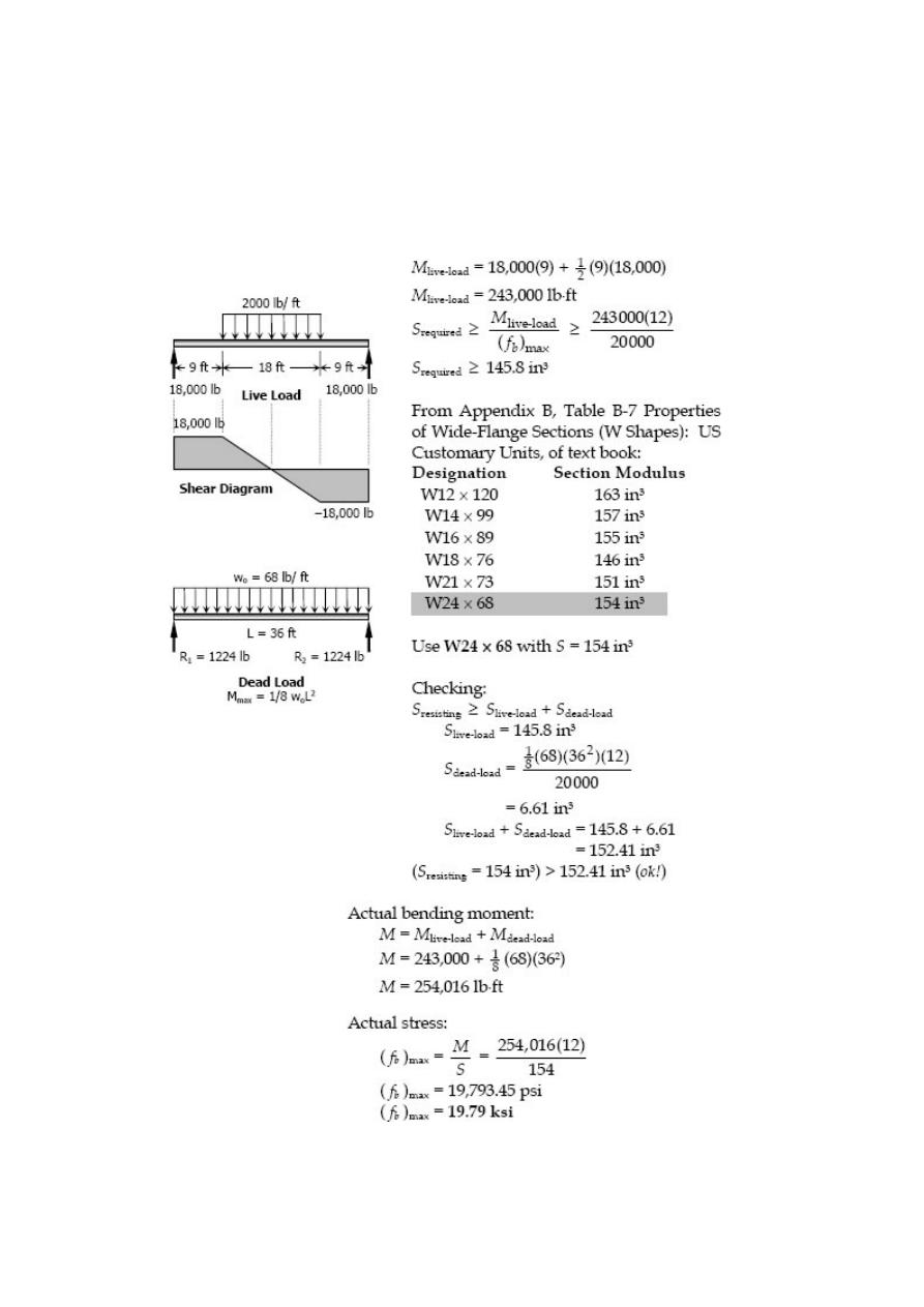
Problem 533
A beam simply supported on a 36-ft span carries a uniformly distributed load of 2000
lb/ft over the middle 18 ft. Using an allowable stress of 20 ksi, determine the lightest
suitable W shape beam. What is the actual maximum stress in the selected beam?
Solution 533
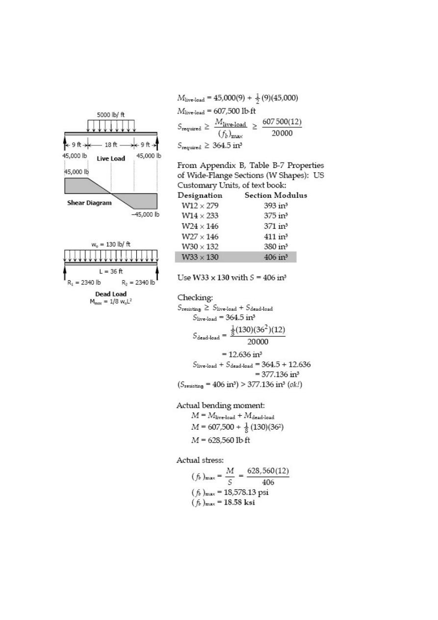
Problem 534
Repeat Prob. 533 if the uniformly distributed load is changed to 5000 lb/ft.
Solution 534
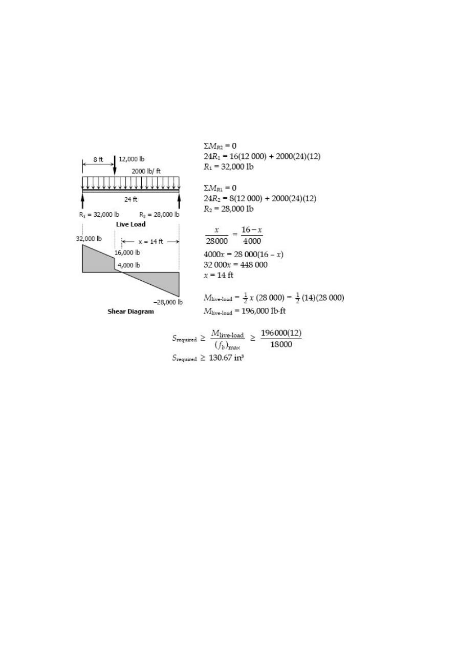
Problem 535
A simply supported beam 24 ft long carries a uniformly distributed load of 2000 lb/ft
over its entire length and a concentrated load of 12 kips at 8 ft from left end. If the
allowable stress is 18 ksi, select the lightest suitable W shape. What is the actual
maximum stress in the selected beam?
Solution 535
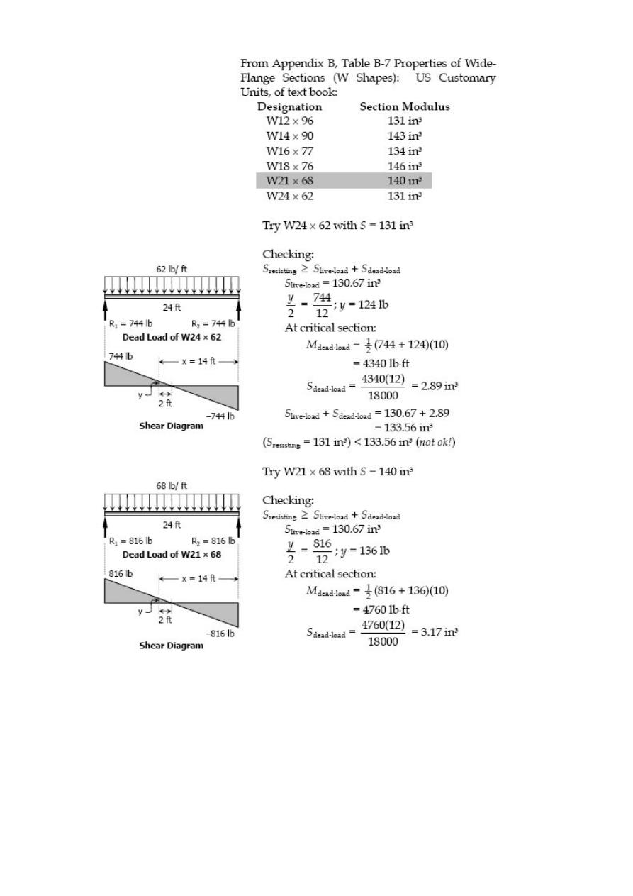
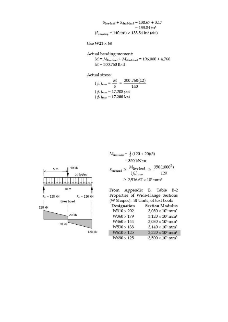
Problem 536
A simply supported beam 10 m long carries a uniformly distributed load of 20 kN/m
over its entire length and a concentrated load of 40 kN at midspan. If the allowable
stress is 120 MPa, determine the lightest W shape beam that can be used.
Solution 536
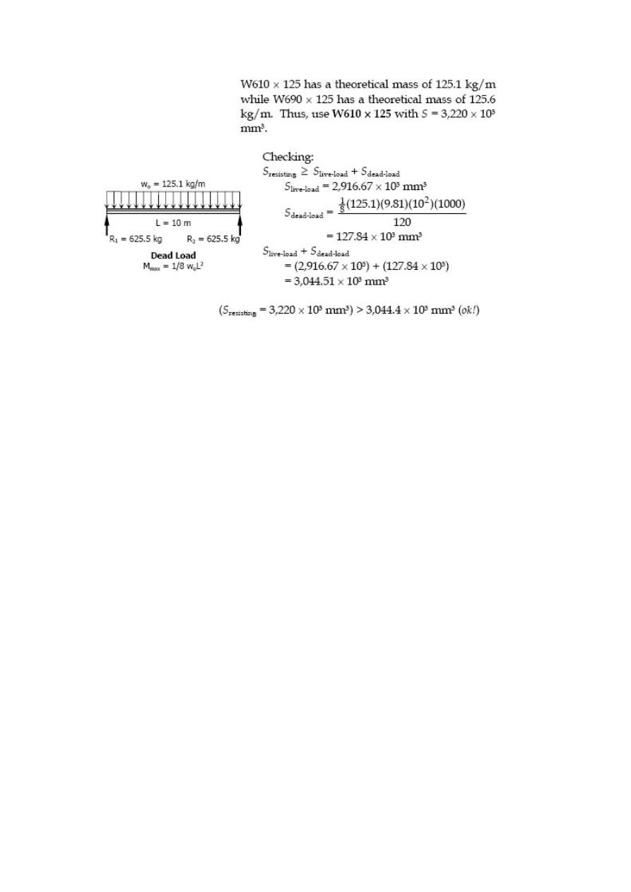
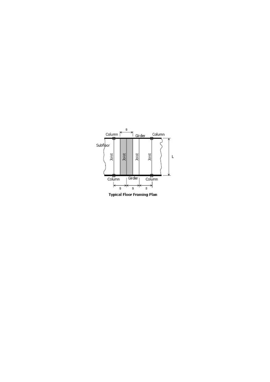
Floor Framing
In floor framing, the subfloor is supported by light beams called floor joists or simply
joists which in turn supported by heavier beams called girders then girders pass the
load to columns. Typically, joist act as simply supported beam carrying a uniform load
of magnitude p over an area of sL,
where
p = floor load per unit area
L = length (or span) of joist
s = center to center spacing of joists and
w
o
= sp = intensity of distributed load in joist.
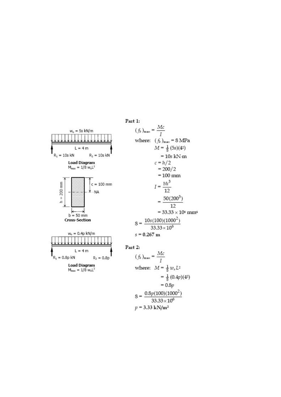
Solved Problems in Floor Framing
Problem 538
Floor joists 50 mm wide by 200 mm high, simply supported on a 4-m span, carry a floor
loaded at 5 kN/m
2
. Compute the center-line spacing between joists to develop a
bending stress of 8 MPa. What safe floor load could be carried on a center-line spacing
of 0.40 m?
Solution 538
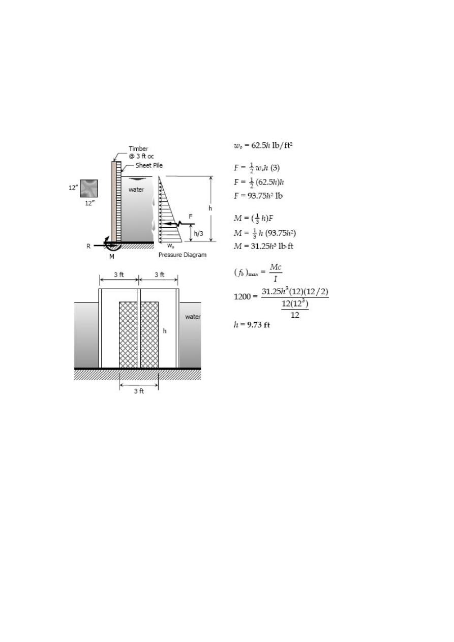
Problem 539
Timbers 12 inches by 12 inches, spaced 3 feet apart on centers, are driven into the
ground and act as cantilever beams to back-up the sheet piling of a coffer dam. What is
the maximum safe height of water behind the dam if water weighs = 62.5 lb/ft
3
and ( f
b
)
max
= 1200 psi?
Solution 539
Problem 540
Timbers 8 inches wide by 12 inches deep and 15 feet long, supported at top and
bottom, back up a dam restraining water 9 feet deep. Water weighs 62.5 lb/ft
3
. (a)
Compute the center-line spacing of the timbers to cause f
b
= 1000 psi. (b) Will this
spacing be safe if the maximum f
b
, ( f
b
)
max
= 1600 psi, and the water reaches its
maximum depth of 15 ft?
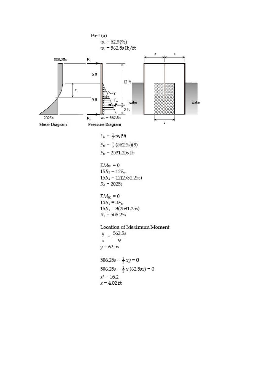
Solution 540
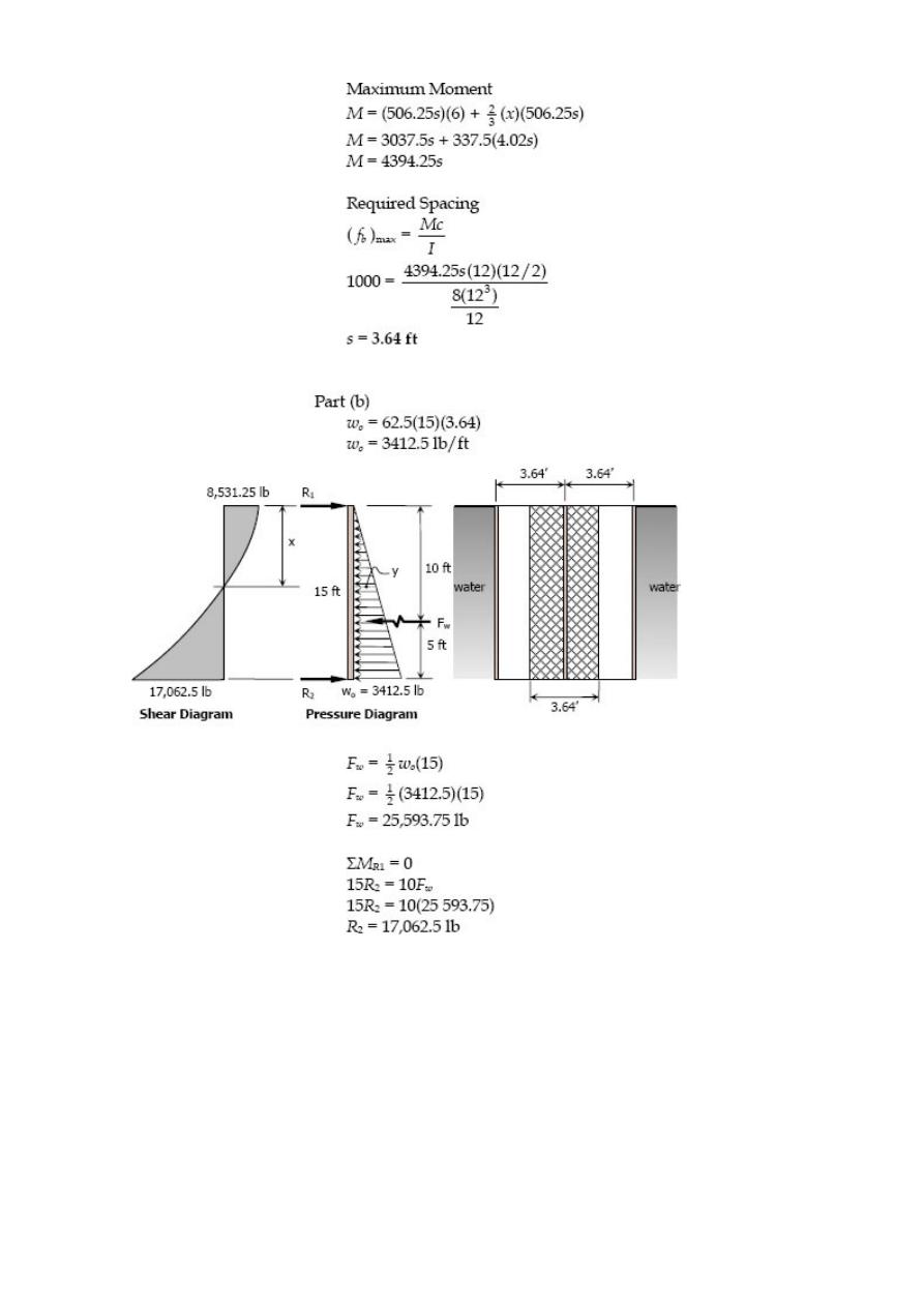
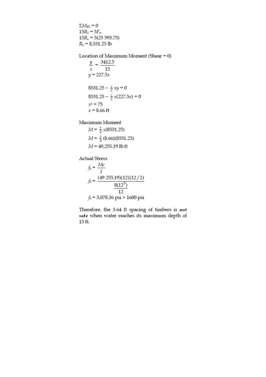
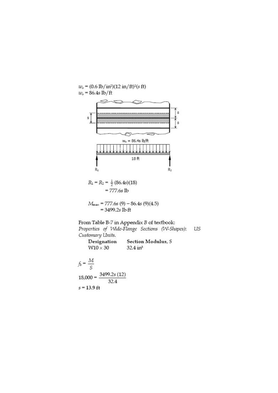
Problem 541
The 18-ft long floor beams in a building are simply supported at their ends and carry a
floor load of 0.6 lb/in
2
. If the beams have W10 × 30 sections, determine the center-line
spacing using an allowable flexural stress of 18 ksi.
Solution 541
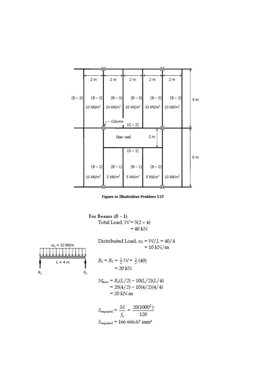
Problem 542
Select the lightest W shape sections that can be used for the beams and girders in
Illustrative Problem 537 of text book if the allowable flexural stress is 120 MPa. Neglect
the weights of the members.
Solution 542
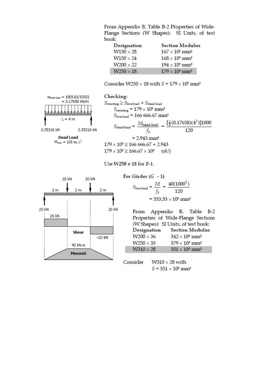
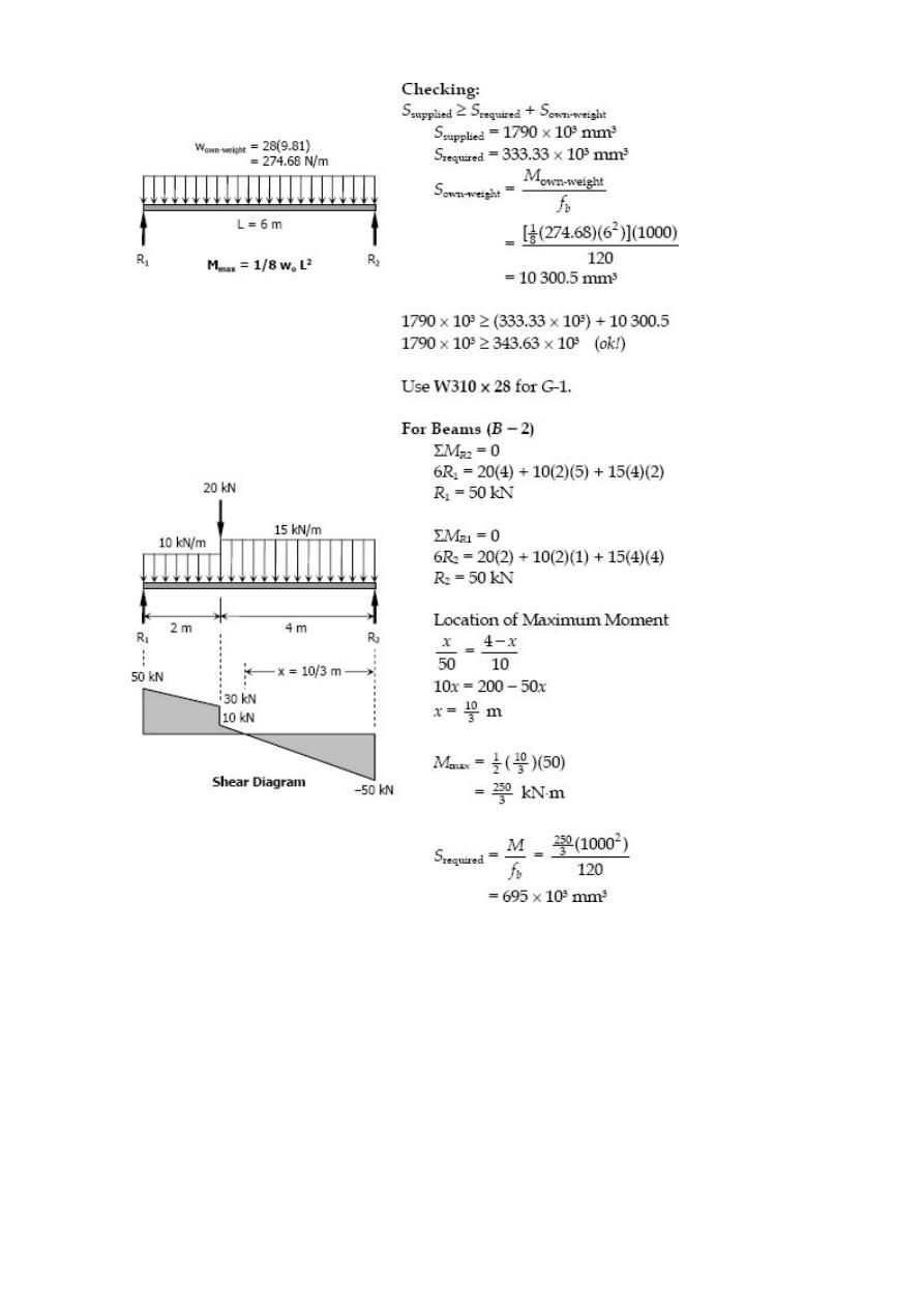
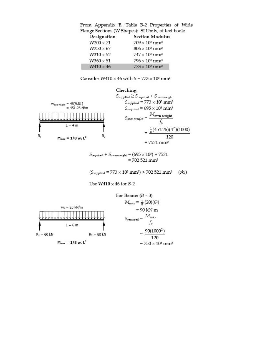
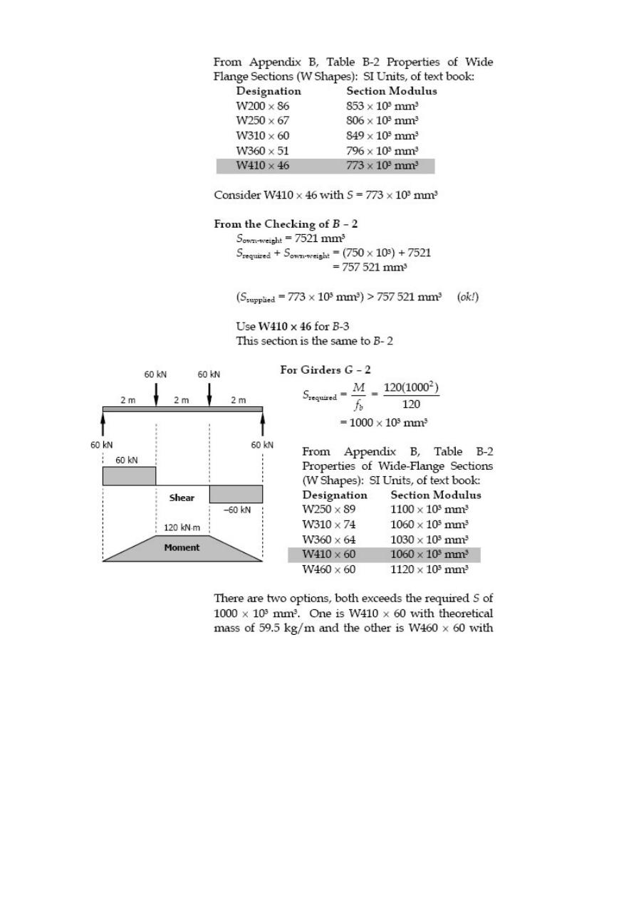
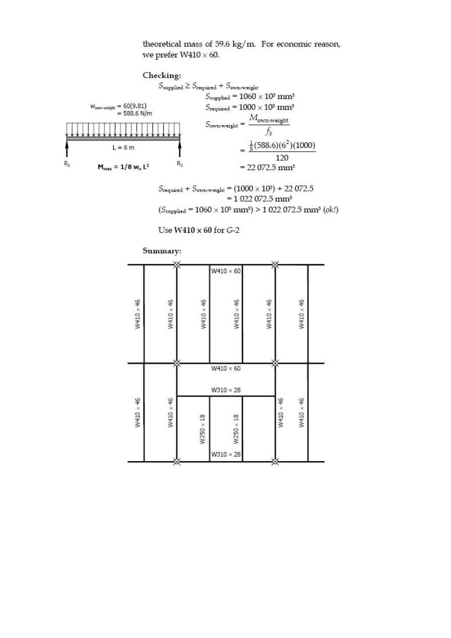
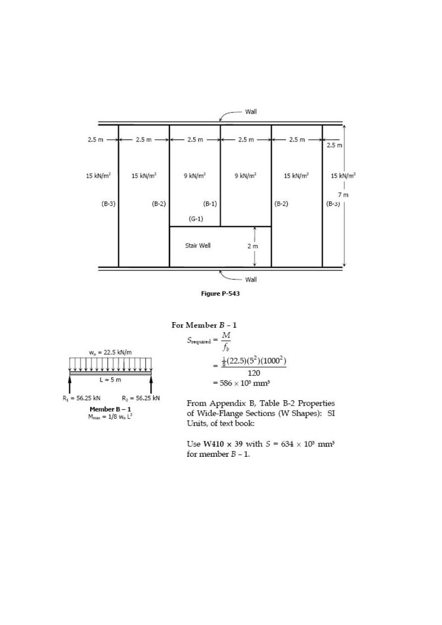
Problem 543
A portion of the floor plan of a building is shown in Fig. P-543. The total loading
(including live and dead loads) in each bay is as shown. Select the lightest suitable W if
the allowable flexural stress is 120 MPa.
Solution 543
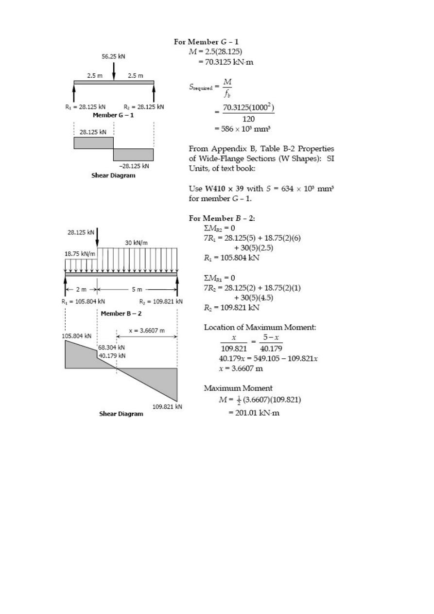
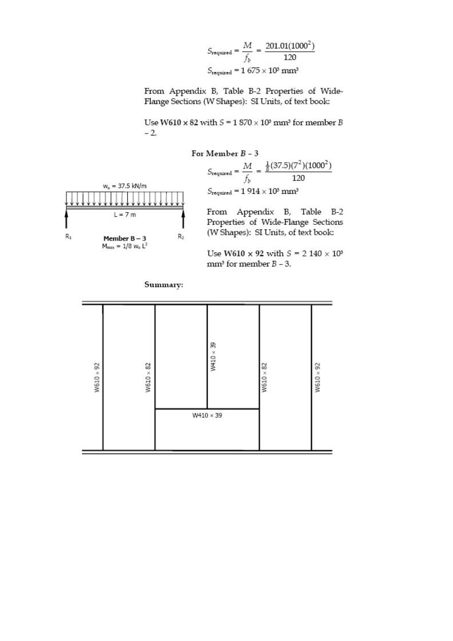

Unsymmetrical Beams
Flexural Stress varies directly linearly with distance from the neutral axis. Thus for a
symmetrical section such as wide flange, the compressive and tensile stresses will be
the same. This will be desirable if the material is both equally strong in tension and
compression. However, there are materials, such as cast iron, which are strong in
compression than in tension. It is therefore desirable to use a beam with unsymmetrical
cross section giving more area in the compression part making the stronger fiber
located at a greater distance from the neutral axis than the weaker fiber. Some of these
sections are shown below.
The proportioning of these sections is such that the ratio of the distance of the neutral
axis from the outermost fibers in tension and in compression is the same as the ratio of
the allowable stresses in tension and in compression. Thus, the allowable stresses are
reached simultaneously.
In this section, the following notation will be use:
f
bt
= flexure stress of fiber in tension
f
bc
= flexure stress of fiber in compression
N.A. = neutral axis
y
t
= distance of fiber in tension from N.A.
y
c
= distance of fiber in compression from N.A.
M
r
= resisting moment
M
c
= resisting moment in compression
M
t
= resisting moment in tension
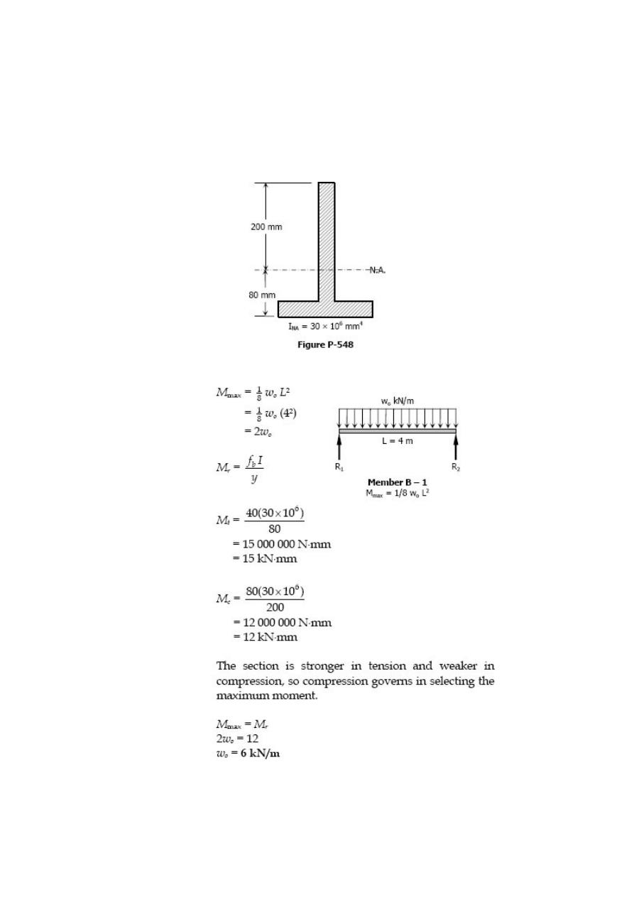
Solved Problems in Unsymmetrical Beams
Problem 548
The inverted T section of a 4-m simply supported beam has the properties shown in Fig.
P-548. The beam carries a uniformly distributed load of intensity w
o
over its entire
length. Determine wo if f
bt
≤ 40 MPa and f
bc
≤ 80 MPa.
Solution 548
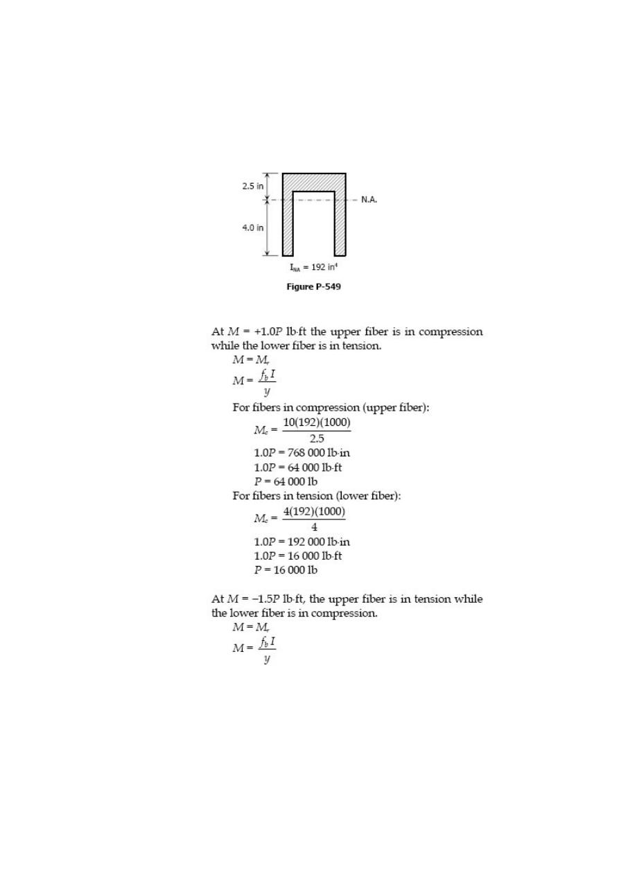
Problem 549
A beam with cross-section shown in Fig. P-549 is loaded in such a way that the
maximum moments are +1.0P lb·ft and -1.5P lb·ft, where P is the applied load in
pounds. Determine the maximum safe value of P if the working stresses are 4 ksi in
tension and 10 ksi in compression.
Solution 549
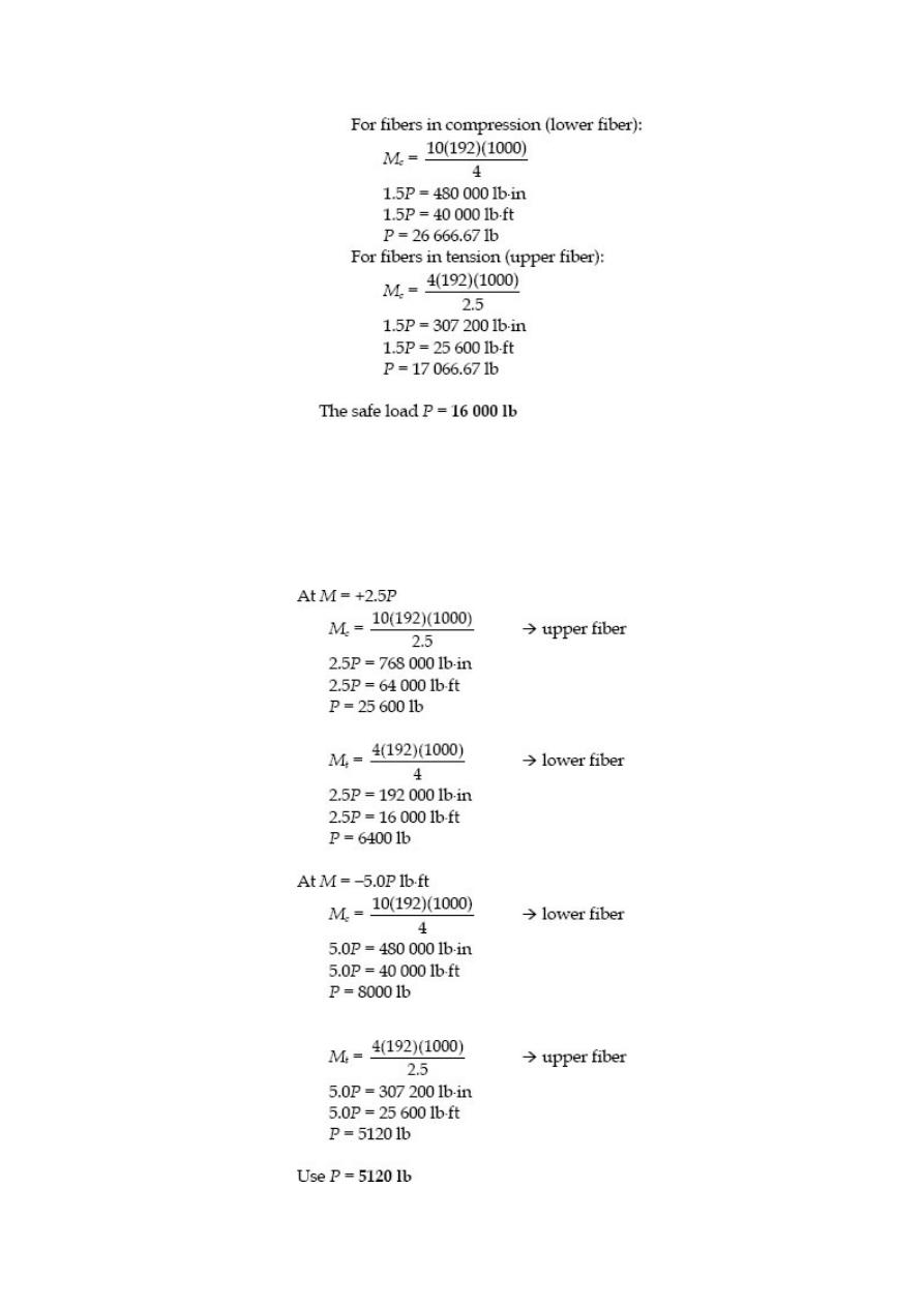
Problem 550
Resolve Prob. 549 if the maximum moments are +2.5P lb·ft and -5.0P lb·ft.
Solution 550
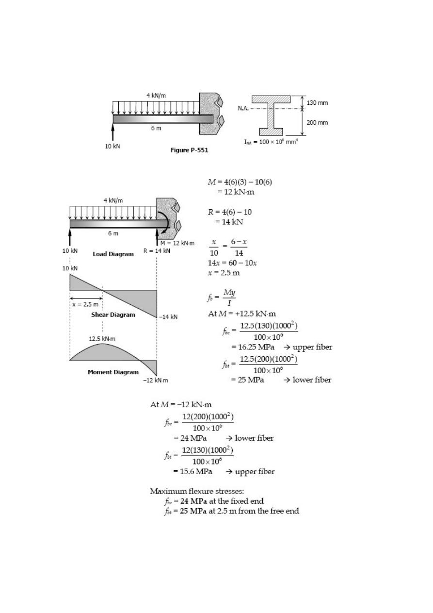
Problem 551
Find the maximum tensile and compressive flexure stresses for the cantilever beam
shown in Fig. P-551.
Solution 551
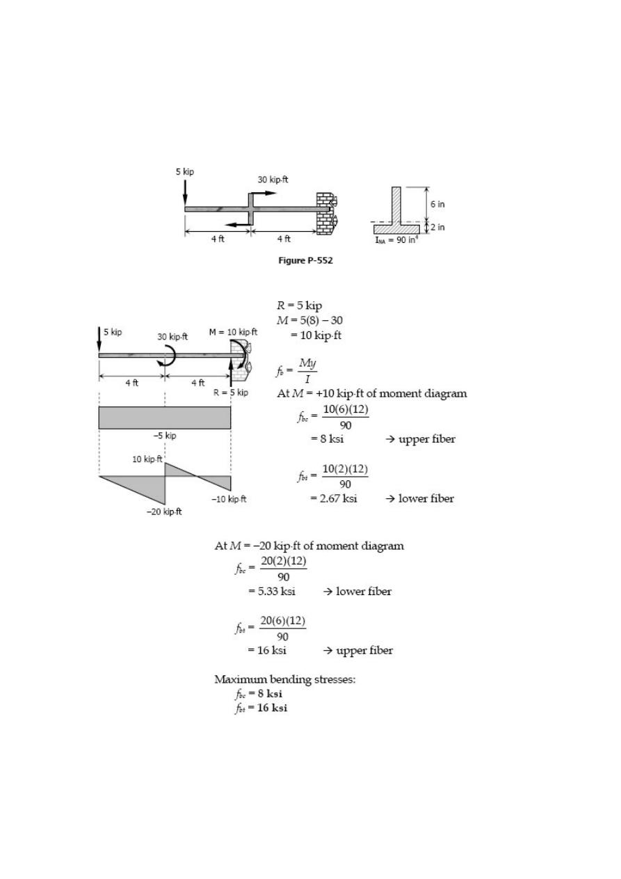
Problem 552
A cantilever beam carries the force and couple shown in Fig. P-552. Determine the
maximum tensile and compressive bending stresses developed in the beam.
Solution 552
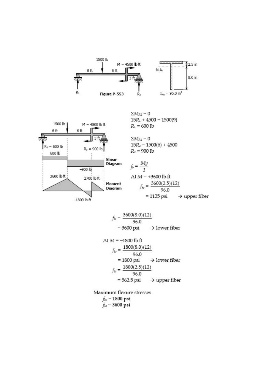
Problem 553
Determine the maximum tensile and compressive bending stresses developed in the
beam as shown in Fig. P-553.
Solution 553
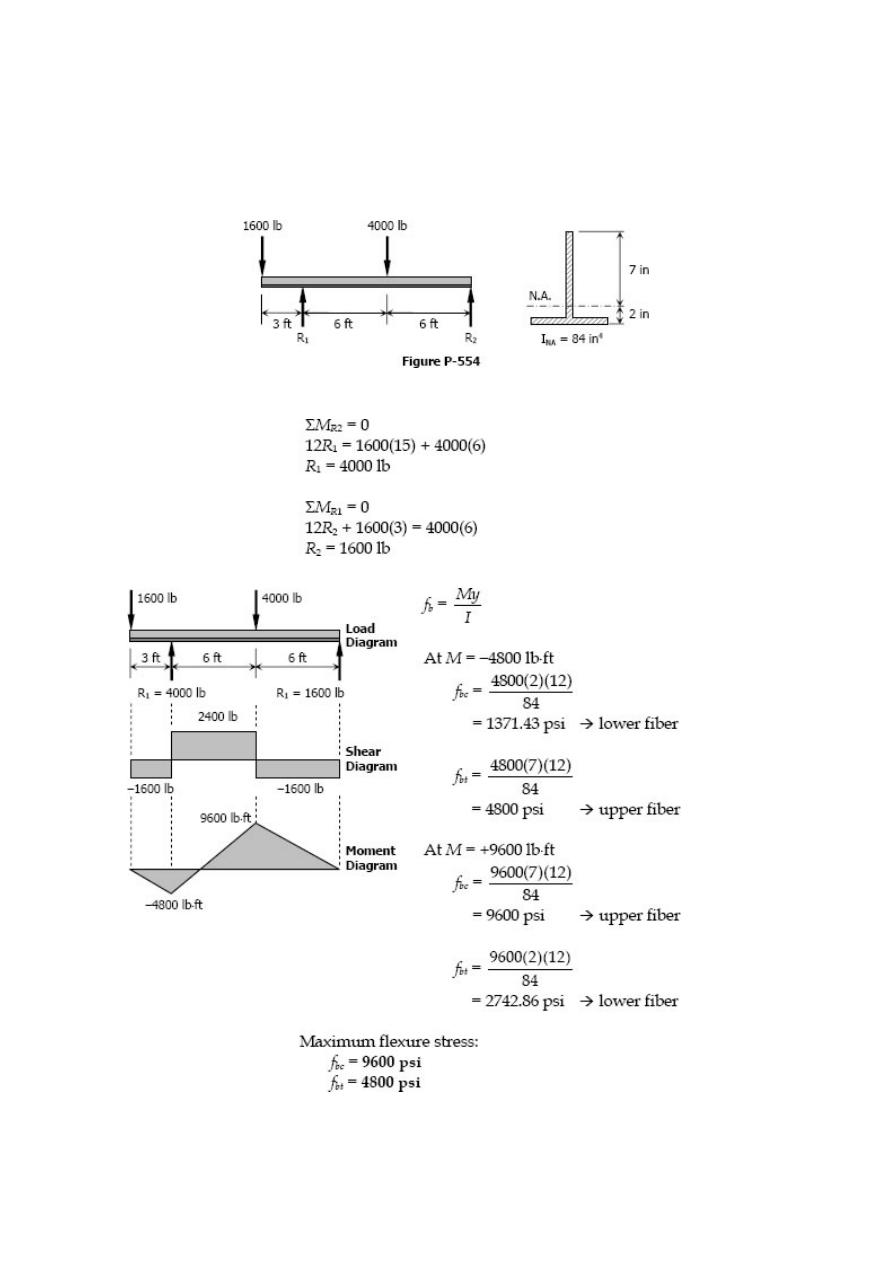
Problem 554
Determine the maximum tensile and compressive stresses developed in the
overhanging beam shown in Fig. P-554. The cross-section is an inverted T with the
given properties.
Solution 554
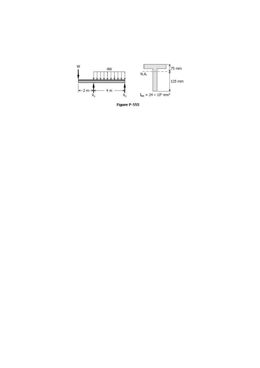
Problem 555
A beam carries a concentrated load W and a total uniformly distributed load of 4W as
shown in Fig. P-555. What safe value of W can be applied if f
bc
≤ 100 MPa and f
bt
≤ 60
MPa? Can a greater load be applied if the section is inverted? Explain.
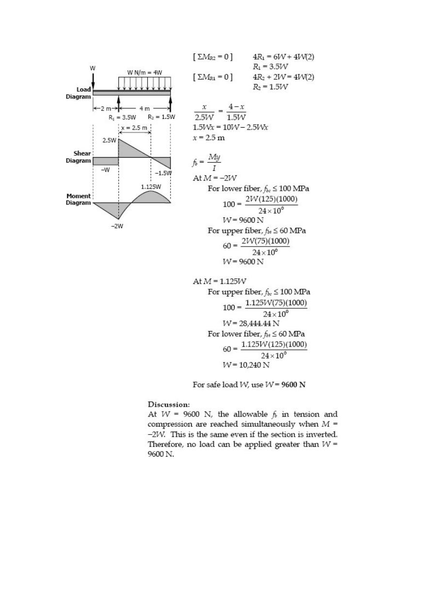
Solution 555
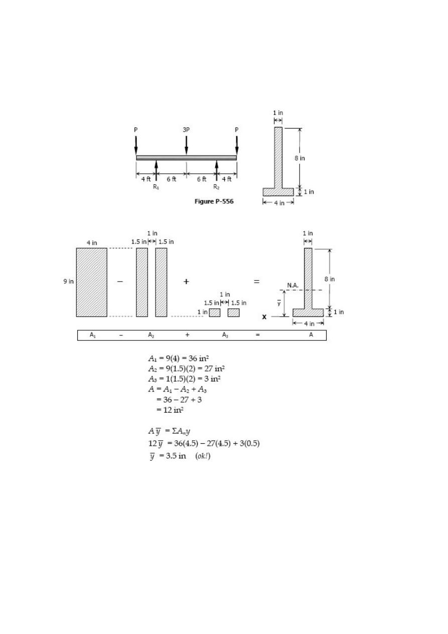
Problem 556
A T beam supports the three concentrated loads shown in Fig. P-556. Prove that the NA
is 3.5 in. above the bottom and that I
NA
= 97.0 in
4
. Then use these values to determine
the maximum value of P so that f
bt
≤ 4 ksi and f
bc
≤ 10 ksi.
Solution 556
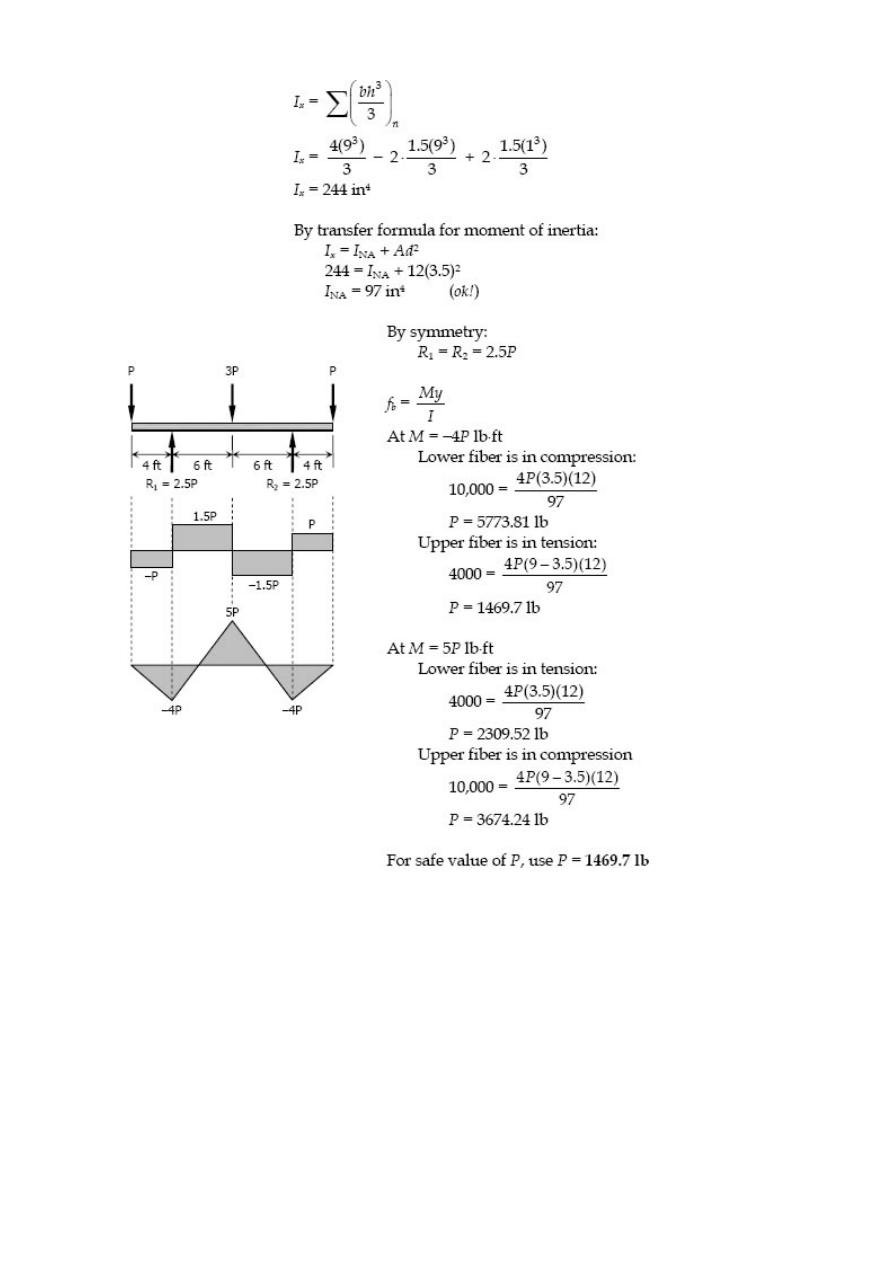
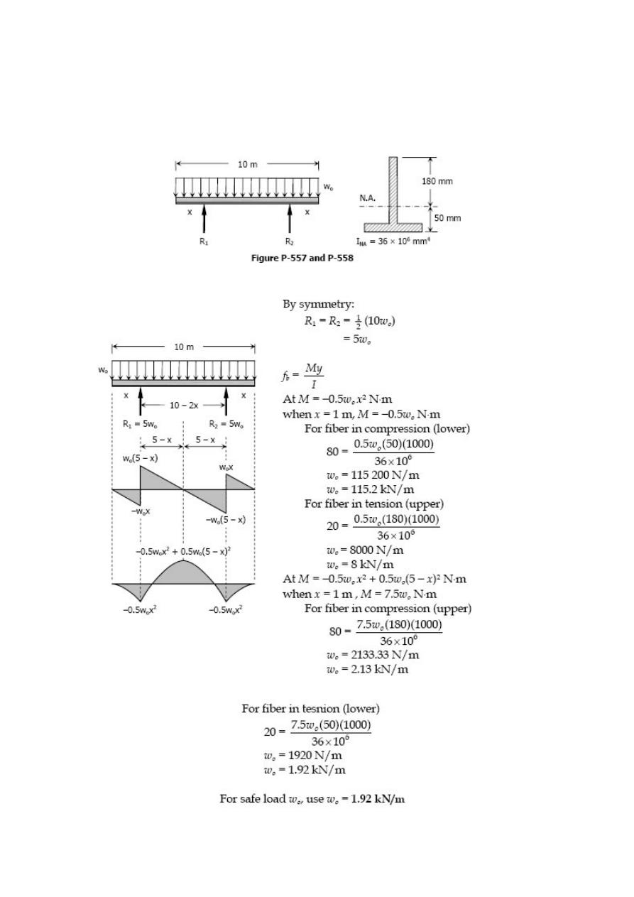
Problem 557
A cast-iron beam 10 m long and supported as shown in Fig. P-557 carries a uniformly
distributed load of intensity wo (including its own weight). The allowable stresses are f
bt
≤ 20 MPa and f
bc
≤ 80 MPa. Determine the maximum safe value of wo if x = 1.0 m.
Solution 557

Problem 558
In Prob. 557, find the values of x and w
o
so that w
o
is a maximum.
Solution 558