MINOR CONNECTORHEIGHT OF CONTOUR-SURVEYING
Lec.6+7
12/12/2016
Assis.Prof.Radhwan H. Hasan1
Minor Connectors
Functions:
Unification and rigidityStress distribution
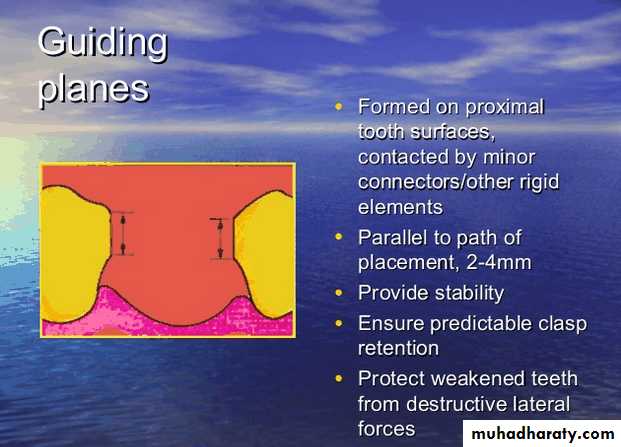
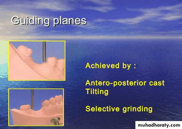
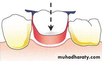
Bracing through contact with guiding planes
Maintain a path of insertion
12/12/2016
Assis.Prof.Radhwan H. Hasan
2
Types of Minor Connectors
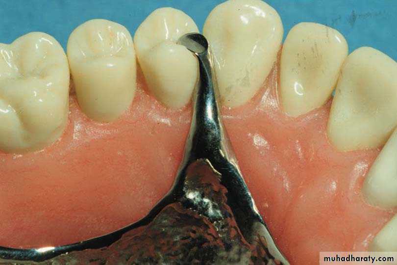
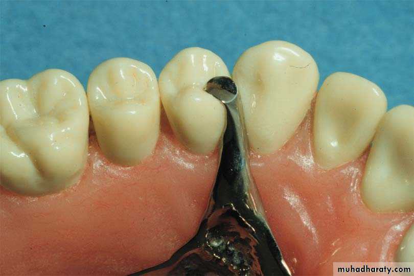
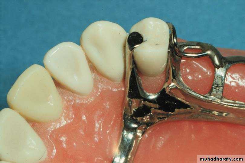
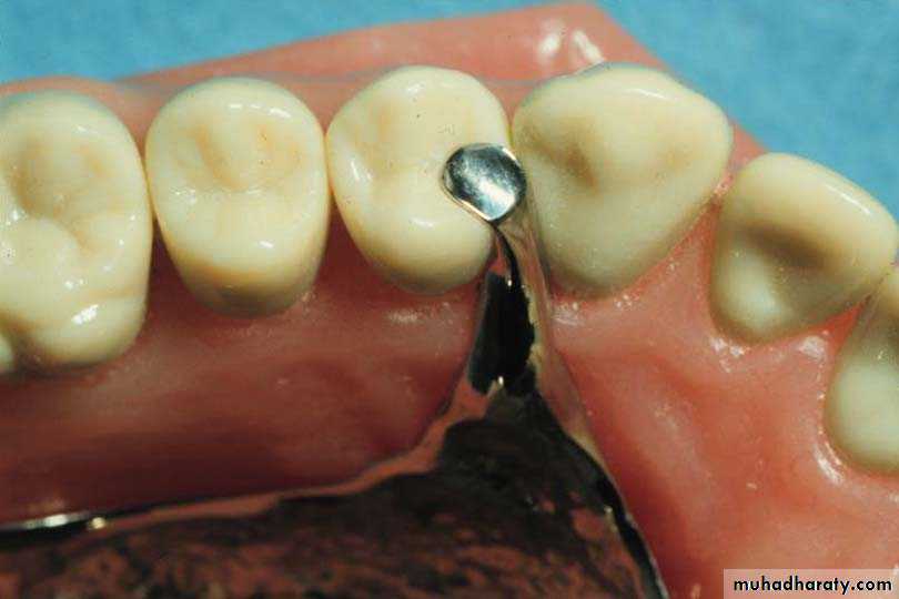
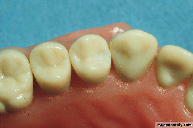
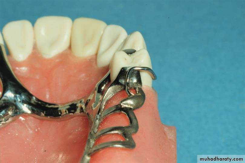
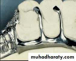
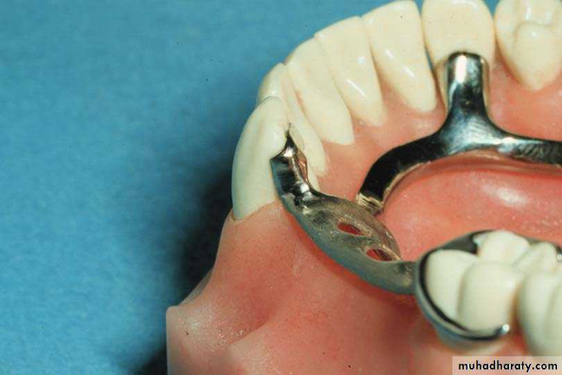
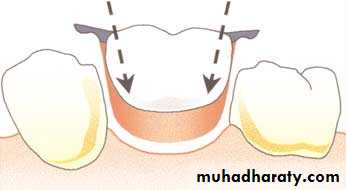
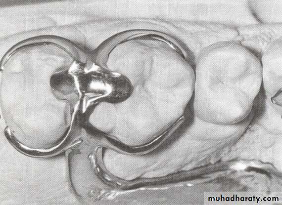
1-Embrasure Minor ConnectorsBetween two adjacent teeth
12/12/2016
Assis.Prof.Radhwan H. Hasan3
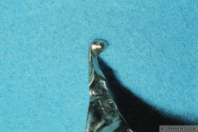
The minor connector is located in the mesio-lingual embrasure but is not in contact with the adjacent tooth (prevents wedging).
12/12/2016
Assis.Prof.Radhwan H. Hasan4
Types of Minor Connectors
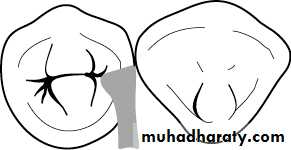
Embrasure Minor ConnectorsTriangular shaped in cross section
Joins major connector at right angles
Relief placed so connector not directly on soft tissue
12/12/2016
Assis.Prof.Radhwan H. Hasan5
Characteristics of Embrasure Minor Connectors
Embrasure Minor Connectors
Contact teeth above height of contour
Prevents wedging & tooth mobility
Alternatively, difficult to seat
12/12/2016
Assis.Prof.Radhwan H. Hasan
6
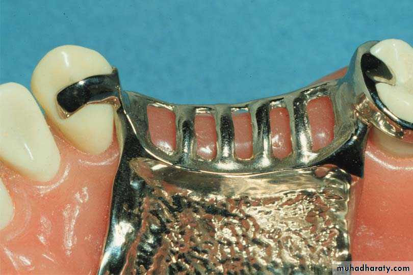
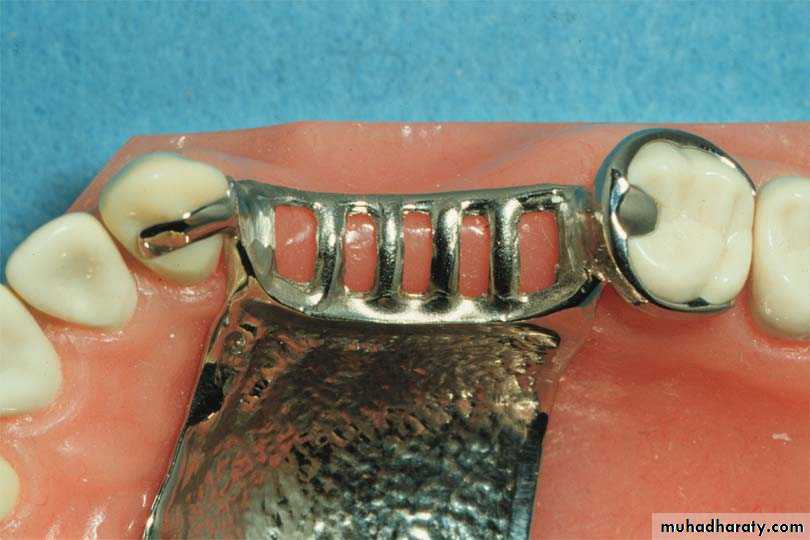
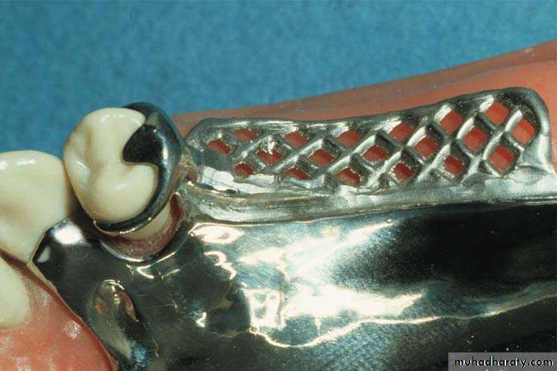
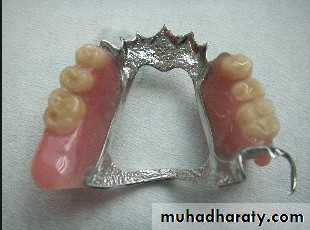
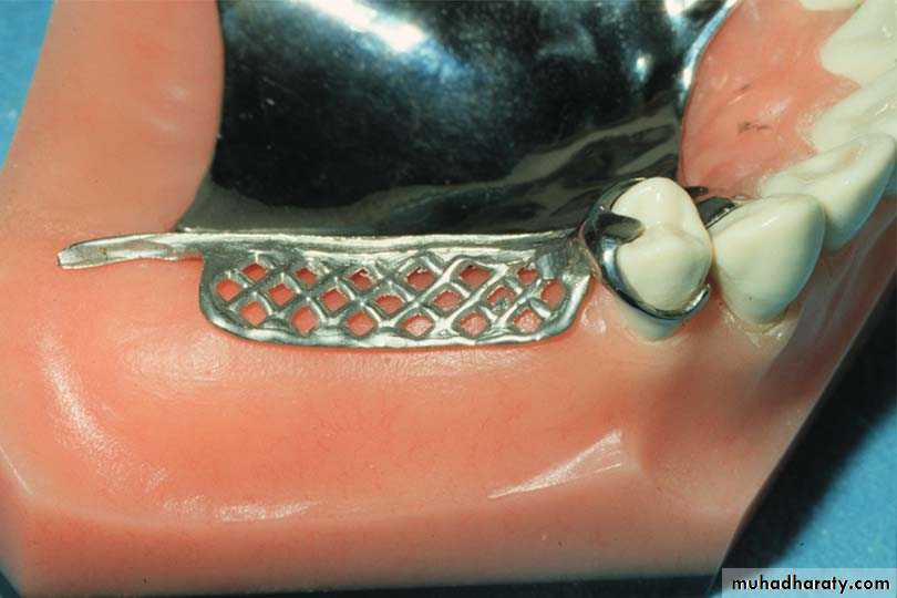
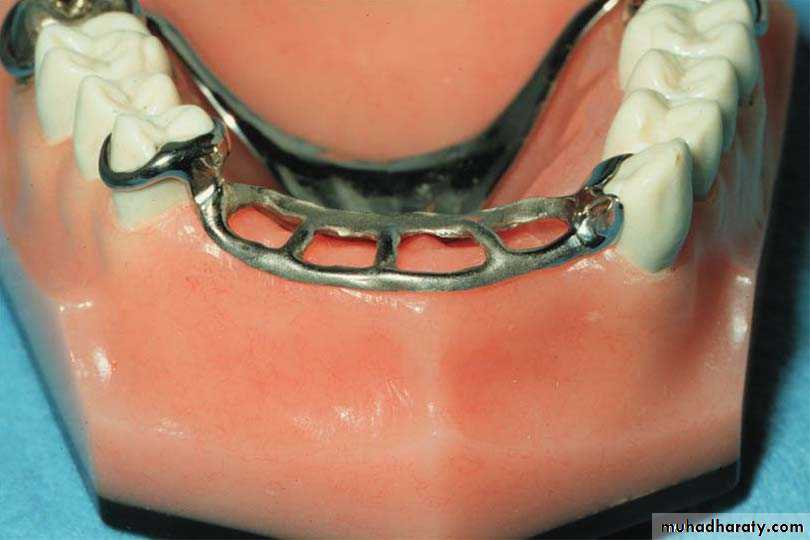
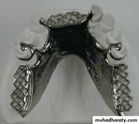
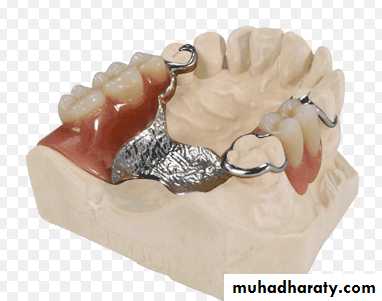
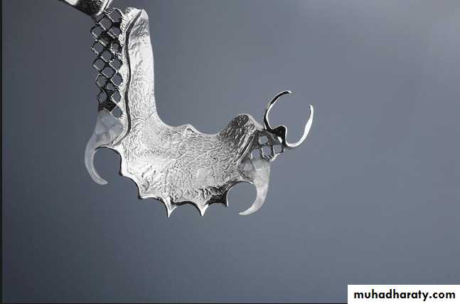
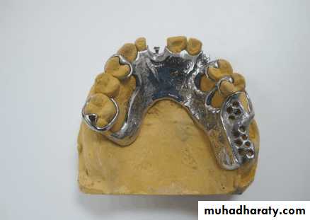
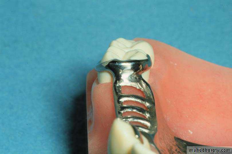
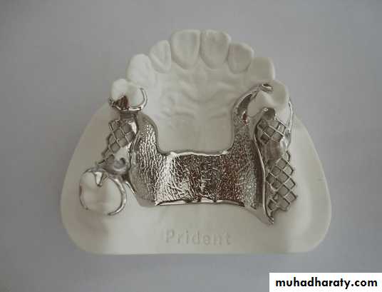
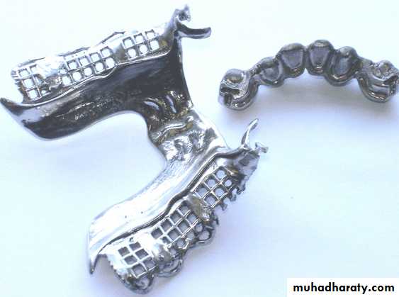
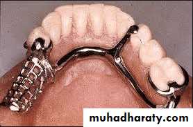
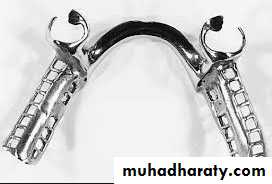
2-Gridwork Minor Connectorsfunction:Connect the denture base and teeth to the major connector
Adjacent edentulous spaces
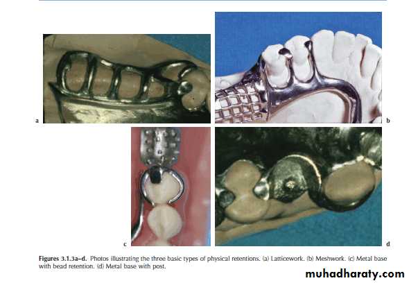
Usually connect major connector to direct retainersTypes: Open lattice work , mesh types, or Nail head retention
12/12/2016
Assis.Prof.Radhwan H. Hasan7
Gridwork Minor Connectors
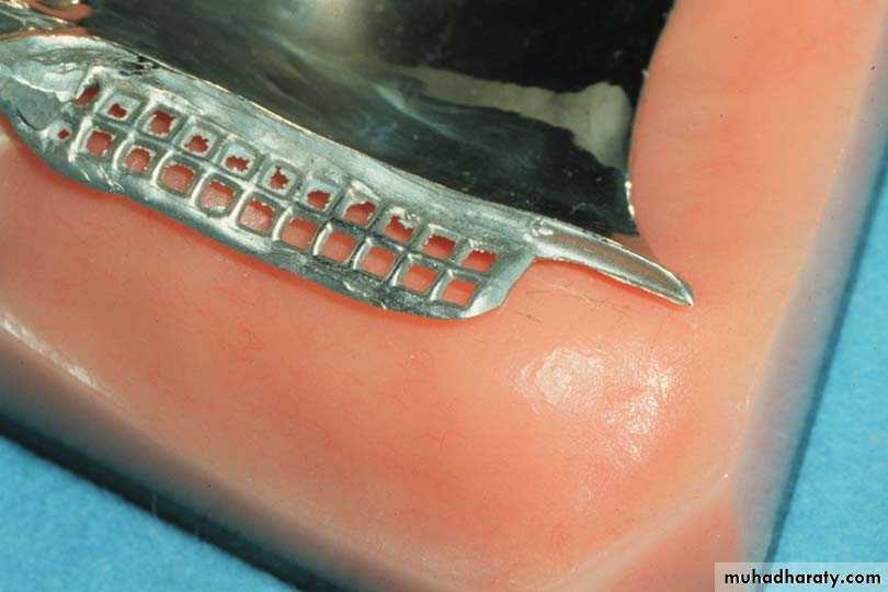
1-Mesh typeFlatter
Potentially more rigid
Less retention for acrylic if openings are small
12/12/2016
Assis.Prof.Radhwan H. Hasan
8
Gridwork Minor Connectors
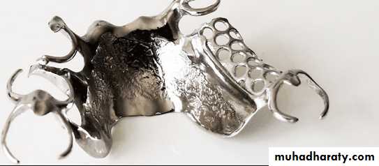
2-Lattice Type
Potentially superior retentionDisadvantages:Interferes with setting of teeth, if struts are too thick
Both types are acceptable if correctly designed
12/12/2016
Assis.Prof.Radhwan H. Hasan
9
12/12/2016
Assis.Prof.Radhwan H. Hasan10
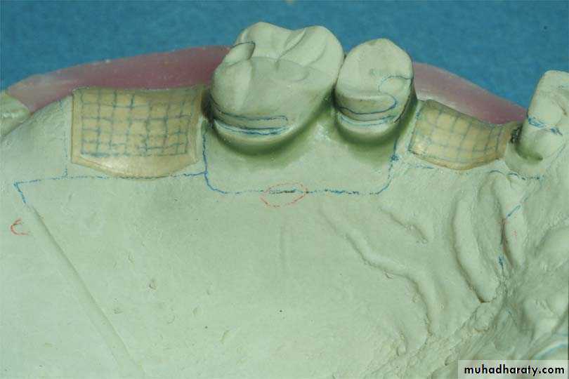
Gridwork Relief
Mechanical retention of denture base resin
Allows the acrylic resin to flow under the gridwork12/12/2016
Assis.Prof.Radhwan H. Hasan11
Gridwork Relief
Relief wax is placed in the edentulous areas1 mm of relief
12/12/2016
Assis.Prof.Radhwan H. Hasan12
Relief Under the Gridwork
Should begin 1.5 - 2 mm from the abutment tooth12/12/2016
Assis.Prof.Radhwan H. Hasan13
Relief Under the Gridwork
Creates a metal to tissue contact adjacent toothPreferable since it wears less
Less porous, (hygiene)
12/12/2016
Assis.Prof.Radhwan H. Hasan
14
Mandibular Gridwork Design
Extend 2/3 of the way from abutment tooth to retromolar padNever on the ascending portion of the ridge
Stewart's, Fig. 2-55
12/12/2016
Assis.Prof.Radhwan H. Hasan
15
Maxillary Gridwork Design
Gridwork2/3 of the length of from abutment to the hamular notch
Major connector
extends fully to the hamular notch
12/12/2016
Assis.Prof.Radhwan H. Hasan16
Gridwork Design
Facially just over the crest of the residual ridge
12/12/2016Assis.Prof.Radhwan H. Hasan
17
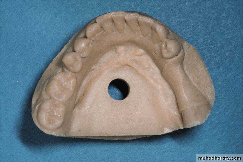
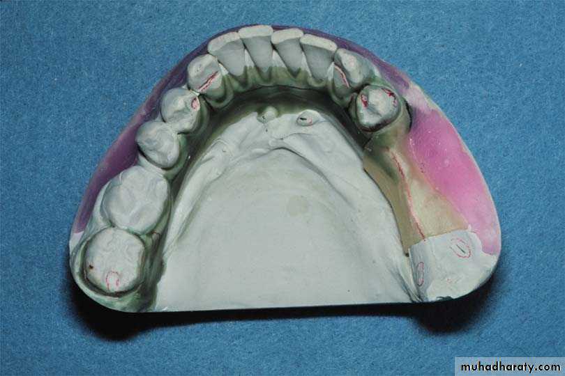
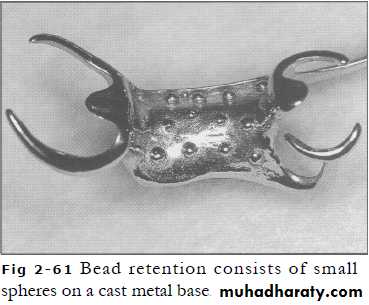
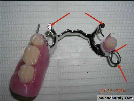
3-Bead wire,post,or Nail head retentionMinor connector
Metal denture base
No relief provided.Retention by projections of metal on this surface.
Projections may be – beads,wires,or nail heads.
Denture base – hygenic because of better soft tissue response to metal
12/12/2016
Assis.Prof.Radhwan H. Hasan
18
12/12/2016
Assis.Prof.Radhwan H. Hasan19
12/12/2016
Assis.Prof.Radhwan H. Hasan
20
12/12/2016
Assis.Prof.Radhwan H. Hasan21
12/12/2016
Assis.Prof.Radhwan H. Hasan22
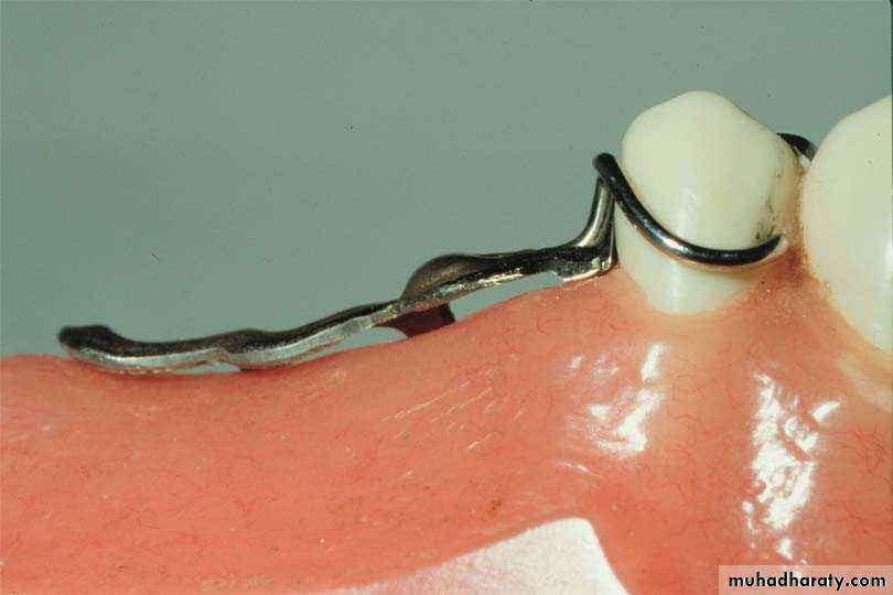
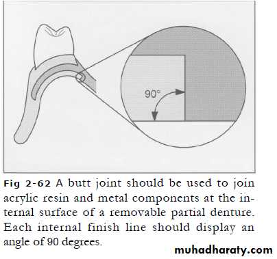
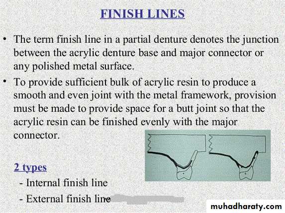
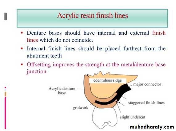
Junction With Major Connector
Butt joint with slight undercut in metalMaximum bulk of the acrylic resin
Prevents thin, weak edges fracturing
12/12/2016
Assis.Prof.Radhwan H. Hasan23
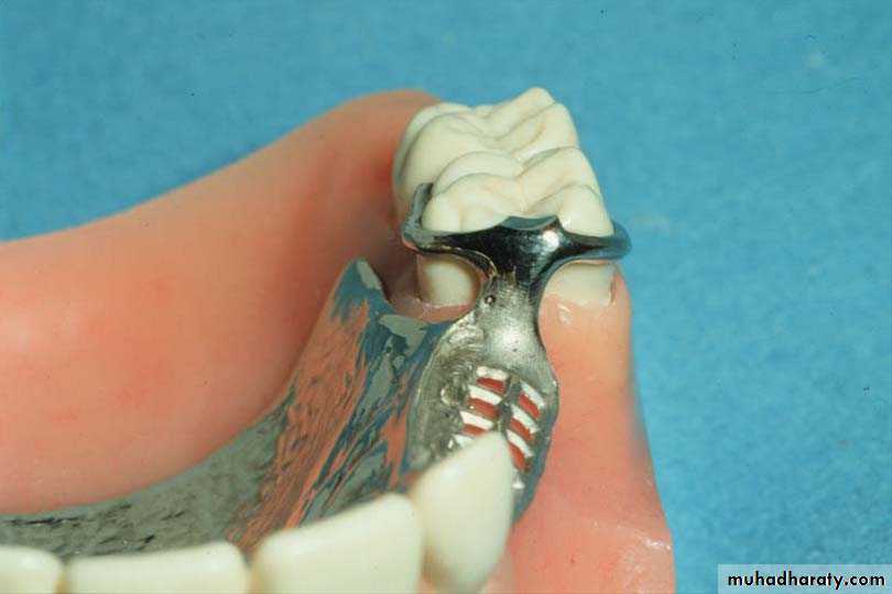
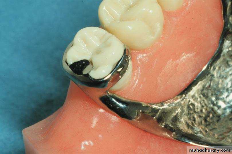
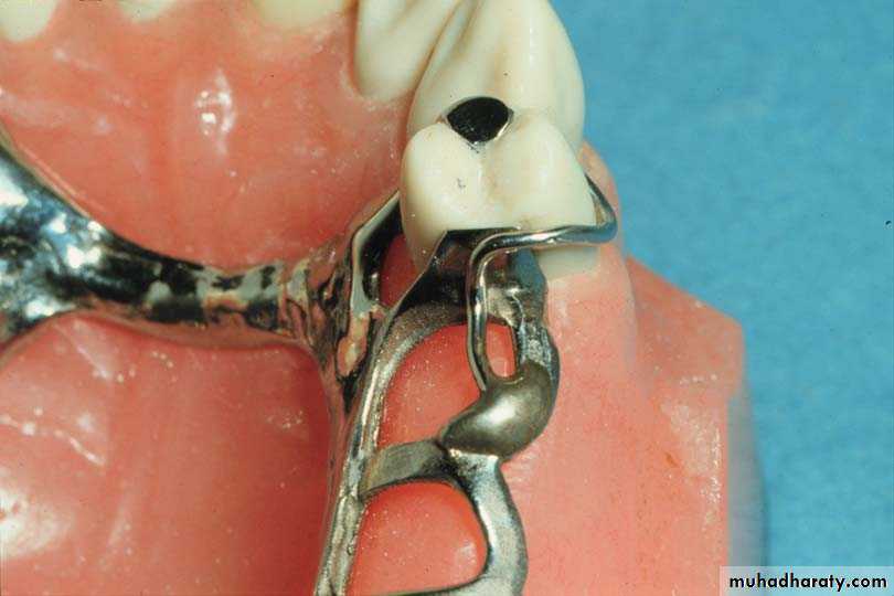
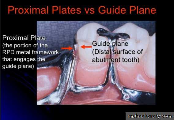
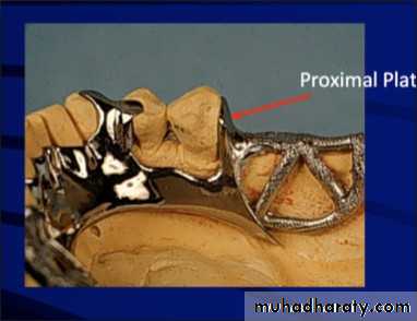
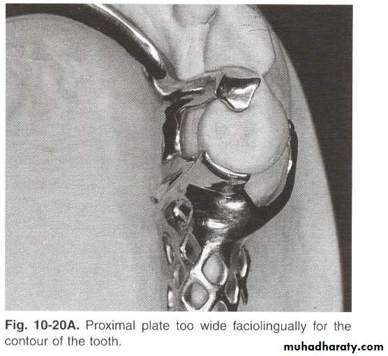
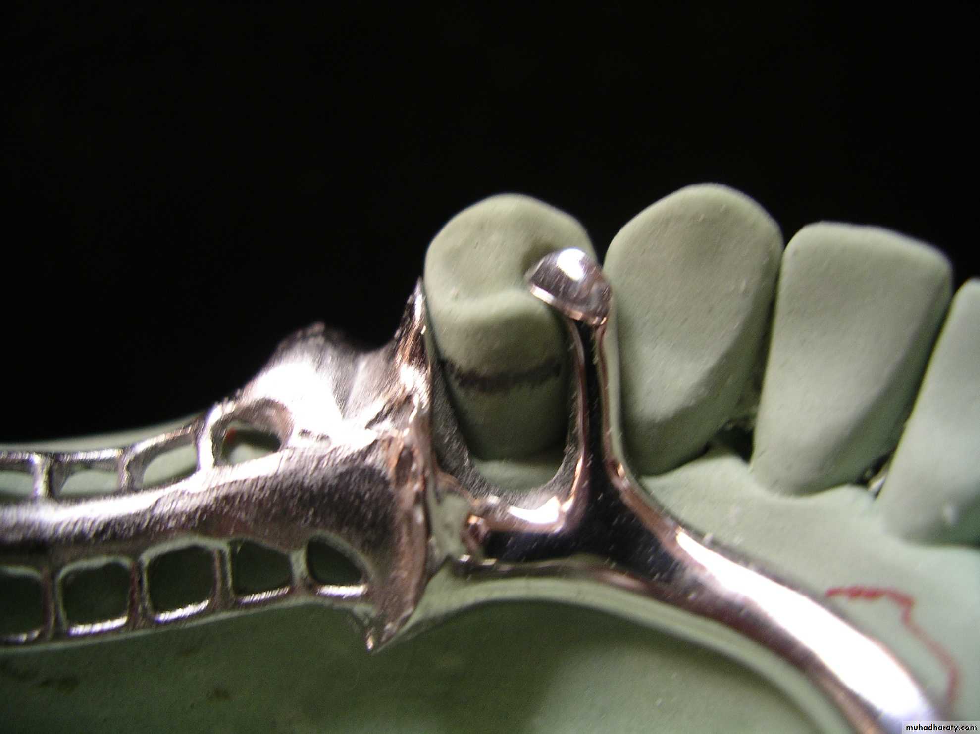
3-Proximal Plates minor connector
Minor connectors originating from the gridwork in an edentulous areaBroad contact with guiding planes
May or may not terminate in an occlusal rest
12/12/2016
Assis.Prof.Radhwan H. Hasan24
Proximal Plates
12/12/2016
Assis.Prof.Radhwan H. Hasan25
12/12/2016
Assis.Prof.Radhwan H. Hasan26
12/12/2016
Assis.Prof.Radhwan H. Hasan27
12/12/2016
Assis.Prof.Radhwan H. Hasan28
Path of insertion and removal.prevent dislodgment of RPD during function
12/12/2016
Assis.Prof.Radhwan H. Hasan29
12/12/2016
Assis.Prof.Radhwan H. Hasan30
12/12/2016
Assis.Prof.Radhwan H. Hasan31
HEIGHT OF CONTOUR-SURVEYING
12/12/2016
Assis.Prof.Radhwan H. Hasan32
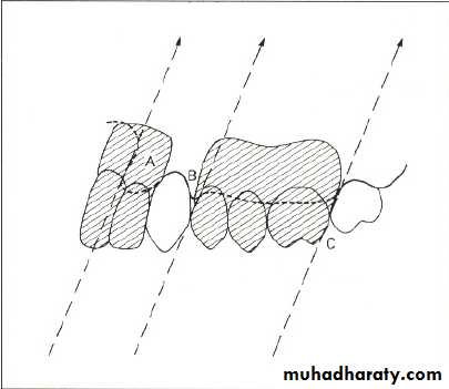
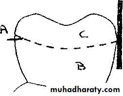
• Buccal view of tooth.
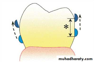
• A: Height of tooth contour B: Undercut area. C: Non undercut area.Undercuts
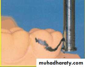
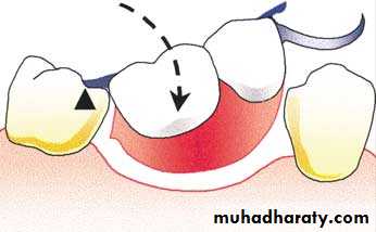
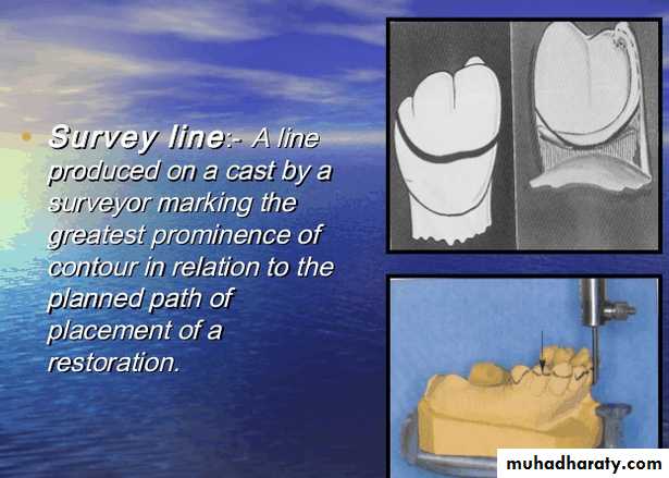
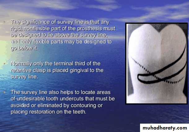
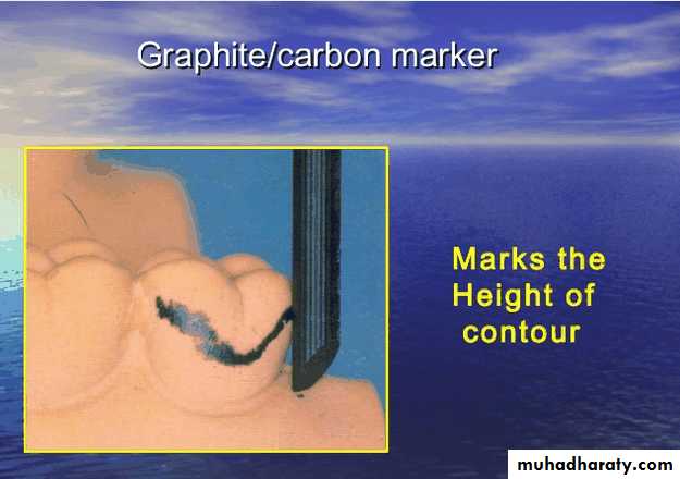
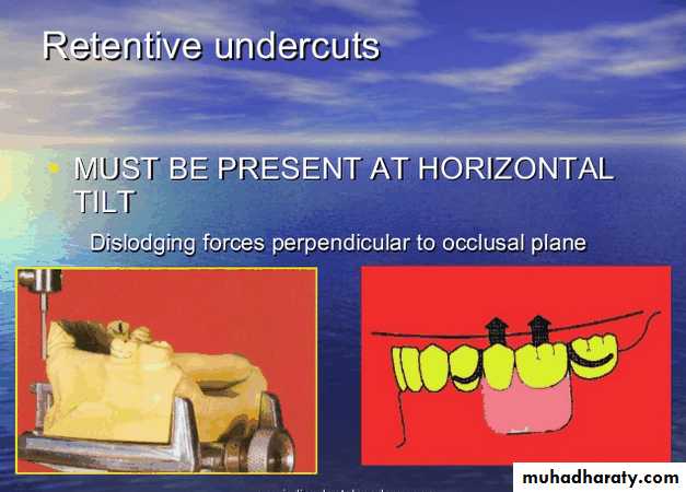
An undercut is formed when the base of an object is smaller than its top. Undercuts on abutment teeth lie below the height of contour, which is the most bulbous and convex part of the tooth also called maximum bulge.
12/12/2016
Assis.Prof.Radhwan H. Hasan33
A partially edentulous mouth has many undercut areas that result due to :
a- Bulbous shape of the crowns of natural teeth resulting in buccal and lingual undercuts, fig.b- The inclination of the long axes of teeth in relation to a vertical line drawn from the occlusal surface, resulting in undercut on the proximal surfaces of these teeth, fig.
c- The inclination of soft tissues or bone to a vertical line drawn from the occlusal surface resulting in soft tissue or bony undercuts, fig.
d- Proliferation of soft tissues covering the edentulous ridge due to the rapid pattern of bone resorption.
12/12/2016
Assis.Prof.Radhwan H. Hasan34
Types of undercuts :
1) Desirable undercuts :Desirable undercuts are used for retaining the partial denture against dislodging forces usually by incorporating retentive flexible clasp arms, less frequently by the denture base engaging a tissue or bony undercut.
2) Undesirable undercuts :
Undercuts other than those used for retention are considered undesirable and should be eliminated.
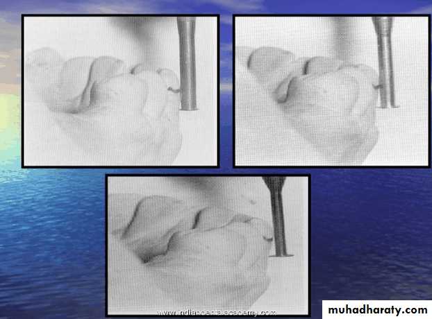
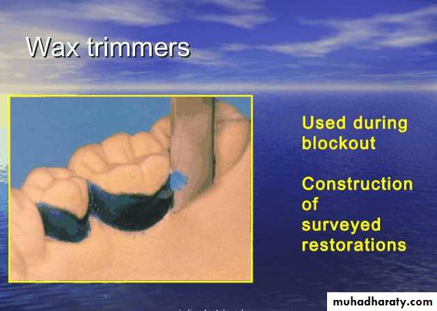
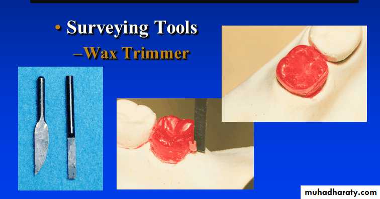
This is done by 1-blocking-out the undercut with wax on the master cast, 2-by the preparation and reduction of the tooth surface in the mouth or 3-by placing a properly contoured crown restoration on the tooth.
In planning for removable partial dentures the prosthodontist should:
1- identify tooth contours, soft tissue or bony undercuts that may interfere with the placement of the denture and that should be corrected in the mouth before construction of the prosthesis.
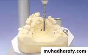
2- analyze the shape of abutment teeth to determine the max. bulge of teeth.
3- The amount of undercut required to provide the best retentive& esthetically satisfactory partial denture.
→ All of this can be achieved by the aid of the dental surveyor
12/12/2016
Assis.Prof.Radhwan H. Hasan
35
12/12/2016
Assis.Prof.Radhwan H. Hasan36
12/12/2016
Assis.Prof.Radhwan H. Hasan37
12/12/2016
Assis.Prof.Radhwan H. Hasan38
12/12/2016
Assis.Prof.Radhwan H. Hasan39
12/12/2016
Assis.Prof.Radhwan H. Hasan40
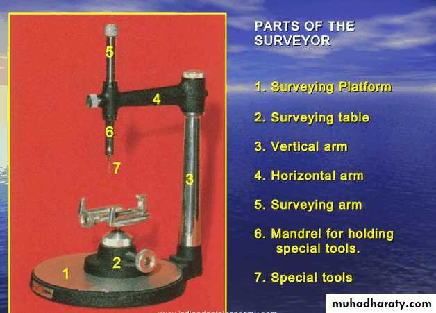
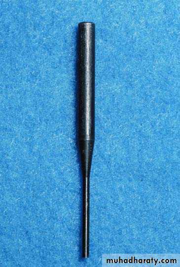
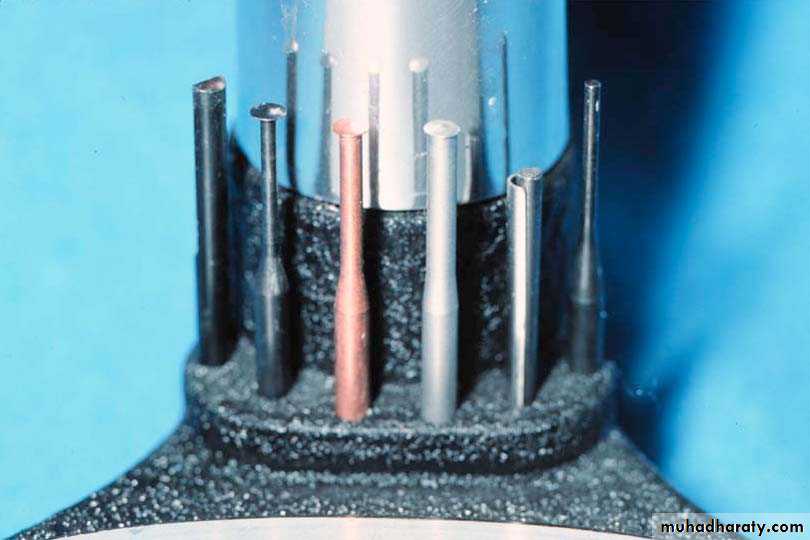
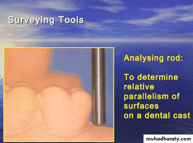
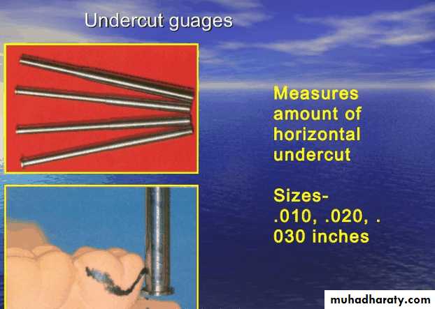
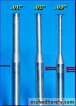
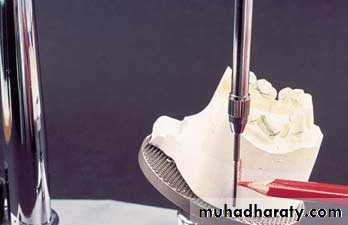
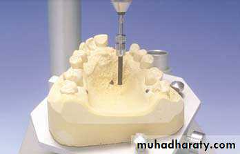
• Surveyor tools
12/12/2016
Assis.Prof.Radhwan H. Hasan41
12/12/2016
Assis.Prof.Radhwan H. Hasan42
12/12/2016
Assis.Prof.Radhwan H. Hasan43
12/12/2016
Assis.Prof.Radhwan H. Hasan44
0.01
0.020.03
12/12/2016
Assis.Prof.Radhwan H. Hasan
45
12/12/2016
Assis.Prof.Radhwan H. Hasan46
12/12/2016
Assis.Prof.Radhwan H. Hasan47
12/12/2016
Assis.Prof.Radhwan H. Hasan48
12/12/2016
Assis.Prof.Radhwan H. Hasan49
12/12/2016
Assis.Prof.Radhwan H. Hasan50
12/12/2016
Assis.Prof.Radhwan H. Hasan51
12/12/2016
Assis.Prof.Radhwan H. Hasan52
12/12/2016
Assis.Prof.Radhwan H. Hasan53
• Path of insertion.
The path followed by the denture from its first contact with the teeth until it is fully seated.This path coincides with the path of withdrawal and may or may not coincide with the path of displacement. There may be a single path or multiple paths of insertion.
12/12/2016
Assis.Prof.Radhwan H. Hasan54
• Path of insertion.
A single path of insertion may be created if sufficient guide surfaces are contacted by the denture; it is most likely to exist when bounded edentulous areas are present.
Path of insertion
12/12/2016Assis.Prof.Radhwan H. Hasan
55
Multiple paths of insertion will exist where guide surfaces are not utilized, for example where the abutment teeth are divergent.
Path of insertion
• Path of insertion.
12/12/2016
Assis.Prof.Radhwan H. Hasan56
Path of insertion
• Path of insertion.• Occasionally a rotational path of insertion can be used.
12/12/2016
Assis.Prof.Radhwan H. Hasan
57
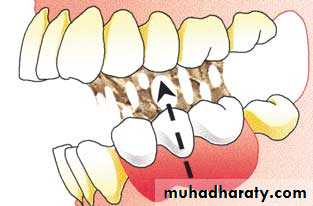
• Path of displacement.
This is the direction in which the denture tends to be displaced in function.The path is variable but is assumed for the purpose of design to be at right angles to the occlusal plane.
Path of displacement.
12/12/2016Assis.Prof.Radhwan H. Hasan
58
Surveying procedure • Final Survey
• Methods of recording the degree of tilt:• The tripod method
• The analyzing rod method
•
12/12/2016
Assis.Prof.Radhwan H. Hasan59
SURVEYING
Horizontal plane,zero plane,Survey line, under cute(amount and position) against displacement,dislodgment(function)
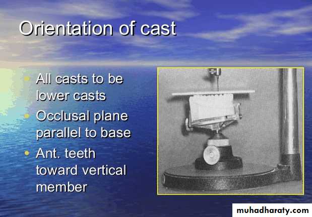
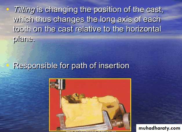
Tillting, path of insertion and removal, interference, under cut ,esthetic, guid planes,
tripoding
First step
Second step
12/12/2016
Assis.Prof.Radhwan H. Hasan60
61
12/12/2016
Assis.Prof.Radhwan H. Hasan
1- Give the name of this action?and Mention its importance
2-Give the name of this clasp? And where it can be used?12/12/2016
Assis.Prof.Radhwan H. Hasan62
1-Which is the most preferable: lingual or incisal rest? Why
2- How much The angle between the minor connector and the rest should be ? And why12/12/2016
63Assis.Prof.Radhwan H. Hasan


