Experiment (7): Transistor as a Switch & a Device Driver
1
2015/2016
Study Objective:
(1) Understanding the characteristic transistors in cut-off and saturation.
(2) Understanding how the transistor to be act as a device driver circuit.
(3) Learning the transistor application in switching and driving.
Introduction:
1. Transistor as a Switch
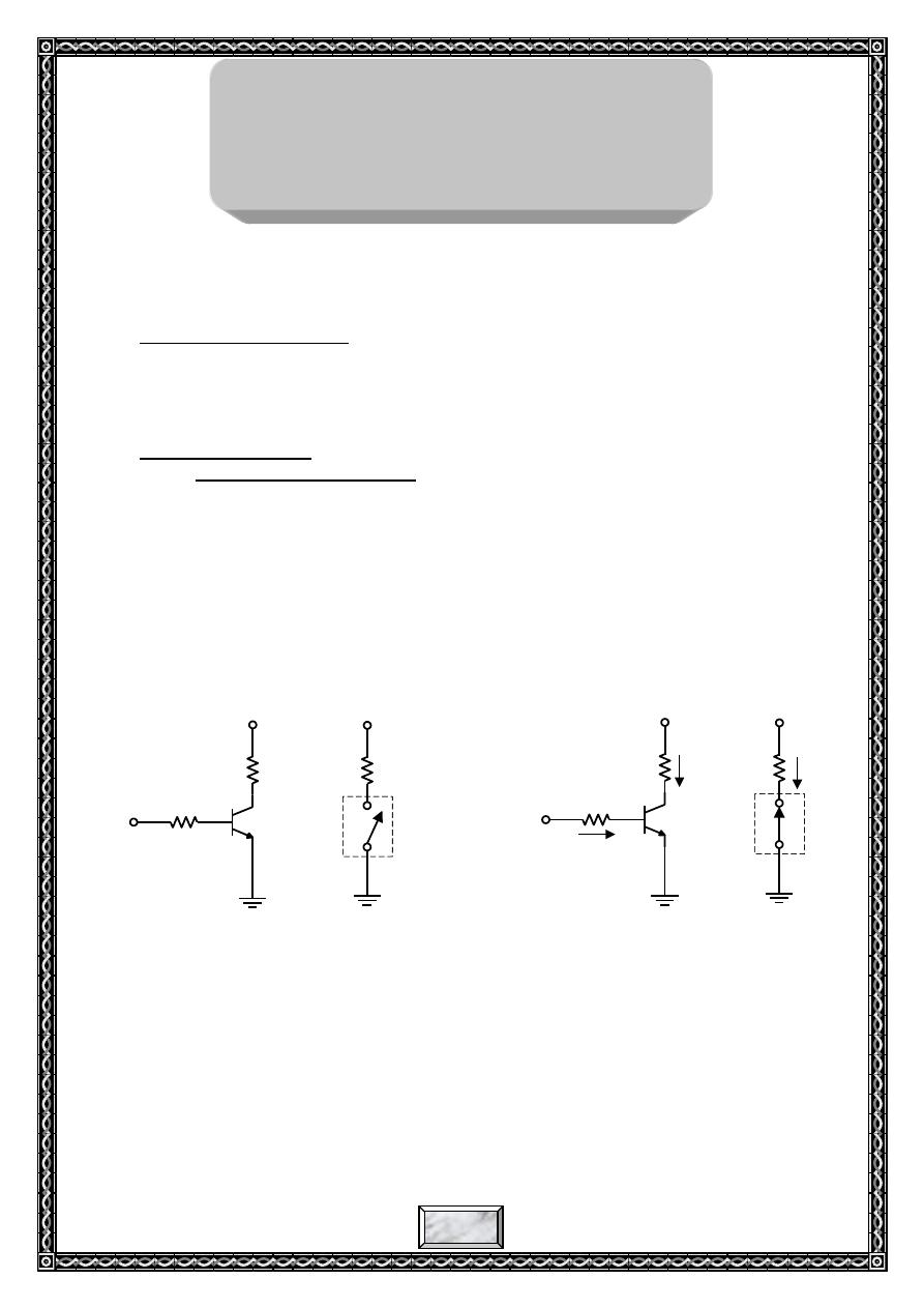
Fig. 1 illustrates the basic operation of the transistor as a switching
device. In Fig. 1a, the transistor is in the cutoff region because the base-emitter
junction is reversed-biased. In this condition, there is, ideally, an open circuit
between collector and emitter, as indicated by the switch equivalent. In Fig.
1b, the transistor is in the saturation region because the base-emitter junction
and the base-collector junction are forward-biased. In this case base current is
made large enough to cause the collector current to reach its saturation value.
In this condition, there is, ideally, a short circuit between collector and emitter
and the equivalent switch is closed as shown in Fig. 1b.
(a) Cutoff-open switch
(b) Saturation-closed switch
Fig. 1: Ideal switching action of a transistor
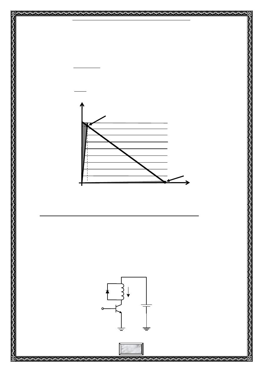
Condition in cutoff:
A transistor is in the cutoff region when the base-emitter
junction in reversed-bias. neglecting leakage current, all of the
currents are zero, and V
CE
is equal to V
CC
(Fig. 2).
CC
CE
V
(cutoff)
V
Experiment No. (5)
Transistor as a Switch &
Device Driver
+V
CC
Q3
R
C
R
B
0 V
I
B
=0
I
C
=0
+V
CC
R
C
C
E
+V
CC
Q3
R
C
R
B
+V
BB
I
B
+V
CC
R
C
C
E
I
C(sat)
I
C(sat)
Experiment (7): Transistor as a Switch & a Device Driver
2
2015/2016
Condition in saturation:
when the base-emitter junction is forward-biased and there is
enough base current to produce a maximum collector current, the
transistor is saturated. The formula for collector saturation current is:
C
sat
CE
CC
sat
C
R
V
V
I
)
(
)
(
The minimum value of base current needed to produce saturation is:
Fig. 2: Output characteristic curves illustrating the cutoff and saturation
conditions
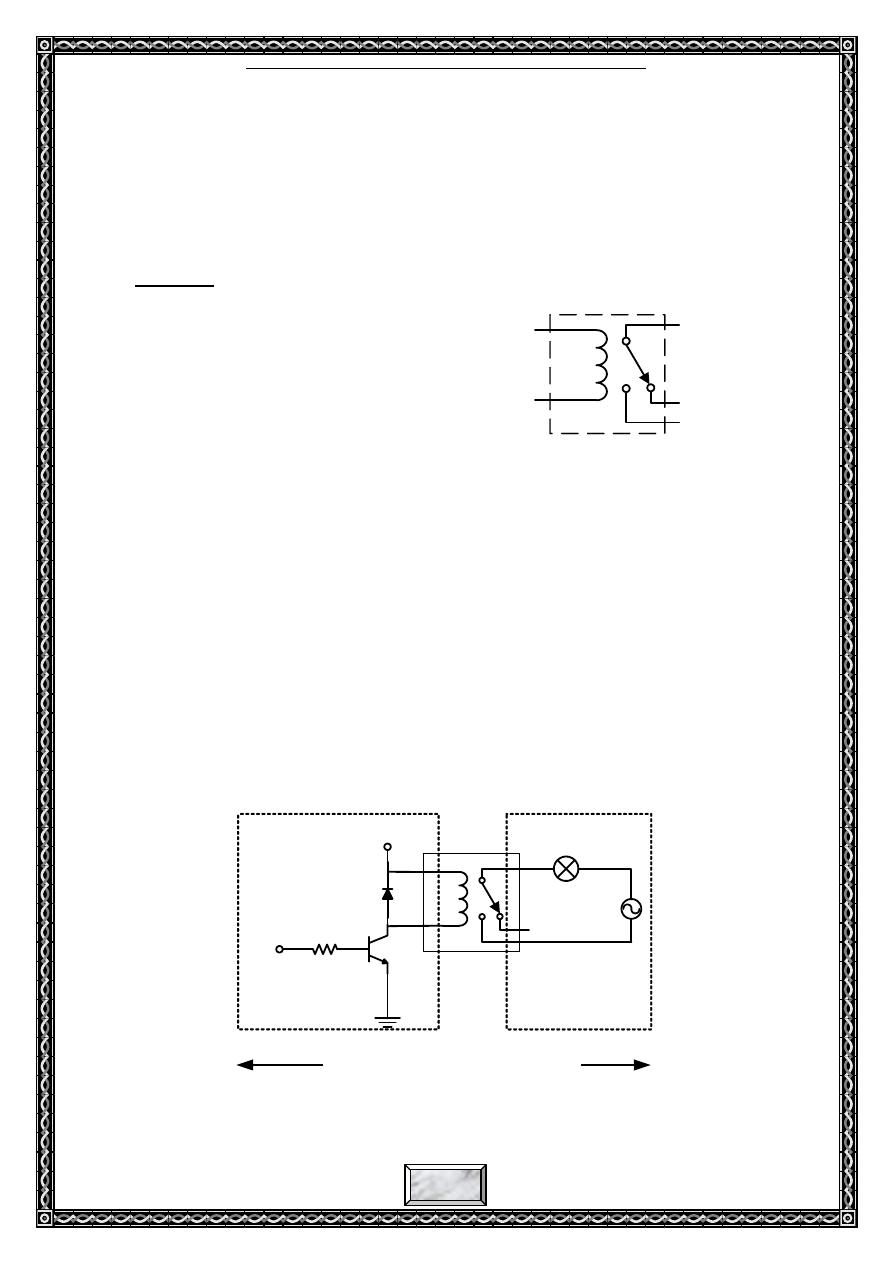
2. Use transistor to drive inductive device such as relay, motor
When the transistor is used to drive inductive device, you shall
consider if the current flowing through Collector during saturation of transistor
conforms to the specified requirements, and you shall also consider if the
voltage applied to Collector during cutoff of transistor will exceed V
CEO
that
the transistor can sustain (V
CEO
: the voltage that CE can sustain during CE
open status of transistor) As shown in Fig. 3, because a reverse electromotive
force will be generated during cutoff of transistor with polarity indicated in
this figure, V
CE
will be two times of V
CC
.
CC
CC
RELAY
CEO
V
V
V
V
2
I
C
+
-
V
CC
+
-
I
C(mA)
V
CE(V)
I
B=0
Saturation
Cutoff
Vcc
I
C
(sat)
V
CE(sat)
0
)
(
(min)
sat
C
B
I
I
Fig. 3
Experiment (7): Transistor as a Switch & a Device Driver
3
2015/2016
In order to eliminate the reverse electromotive force generated by
inductive device during cutoff of transistor, a diode can be connected in
parallel across two terminals of the coil, shown in Fig .2. as the discharge
circuit for the reverse electromotive force. V
CEO
can thus be decreased, and
achieve the function for protection of transistor.
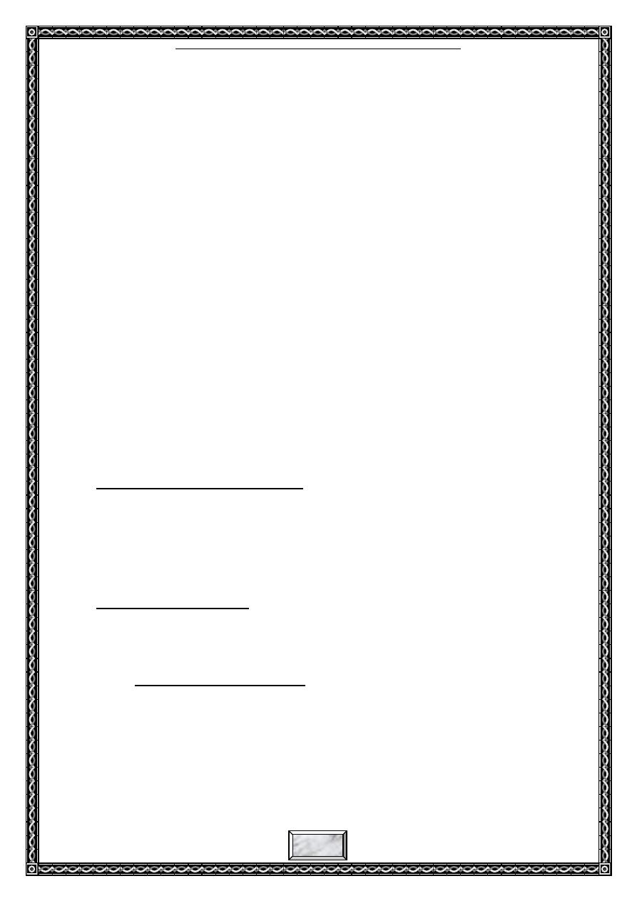
3. Relays
A relay is an electro-mechanical
switch. It consists of a coil and moveable
iron lever (Fig. 4). when current flowing
through the coil of the relay creates a
magnetic field which attracts a lever and
changes the switch contact. The coil current
can be on or off so relays have two switch
positions and they are double throw
switches.
The relay's switch connections are usually labeled COM, NC and NO:
COM = Common, this is the fixed side of the moving lever.
NC = Normally Closed, point COM is connected to this point when the
relay coil is off.
NO = Normally Open, point COM is connected to this point when the
relay coil is on.
Relays allow one circuit to switch a second circuit (AC or DC) which
can be completely separate from the first. For example a low voltage battery
circuit can use a relay to switch a 220V AC mains circuit as shown in Fig. 5.
There is no electrical connection inside the relay between the two circuits, the
link is magnetic and mechanical.
Fig. 5: A transistor drives an AC circuit
AC
V
CC
R
B
V
in
Lamp
Relay
High Voltage Circuit
Low Voltage Circuit
Electrically Separated Circuits
NO
COM
NC
COM
NC
NO
Relay
Coil
Fig. 4: A relay
Moveable lever
Experiment (7): Transistor as a Switch & a Device Driver
4
2015/2016
Like relays, transistors can be used as an electrically operated switch.
for switching a small DC currents (< 1A) at low voltage they are usually a
better choice than a relay. However transistors cannot switch AC or high
voltages (such as mains electricity) and they are not usually a good choice for
switching large currents (> 5A). In these cases a relay will be needed, but note
that a low power transistor may still be needed to switch the current for the
relay's coil. The main advantages and disadvantages of relays are listed below:
Advantages of relays:
Relays can switch AC and DC, transistors can only switch DC.
Relays can switch high voltages, transistors cannot.
Relays are a better choice for switching large currents (> 5A).
Relays can switch many contacts at once.
Disadvantages of relays:
Relays are bulkier than transistors for switching small currents.
Relays cannot switch rapidly, transistors can switch many times per
second.
Relays use more power due to the current flowing through their coil.
Relays require more current than many ICs can provide, so a low
power transistor may be needed to switch the current for the relay's
coil.
Experiment Equipments:
(1) KL-200 Linear Circuit Lab.
(2) Experiment Module: KL-23003.
(3) Experiment Instrument: 1. Multimeter or digital multimeter.
2. Oscilloscope.
(4) Tools: Basic hand tools.
(5) Materials: As indicated in the KL-23003.
Experiment Items:
Item One (1): Experiment for ON (saturation) and OFF (cutoff)
currents of transistor
.
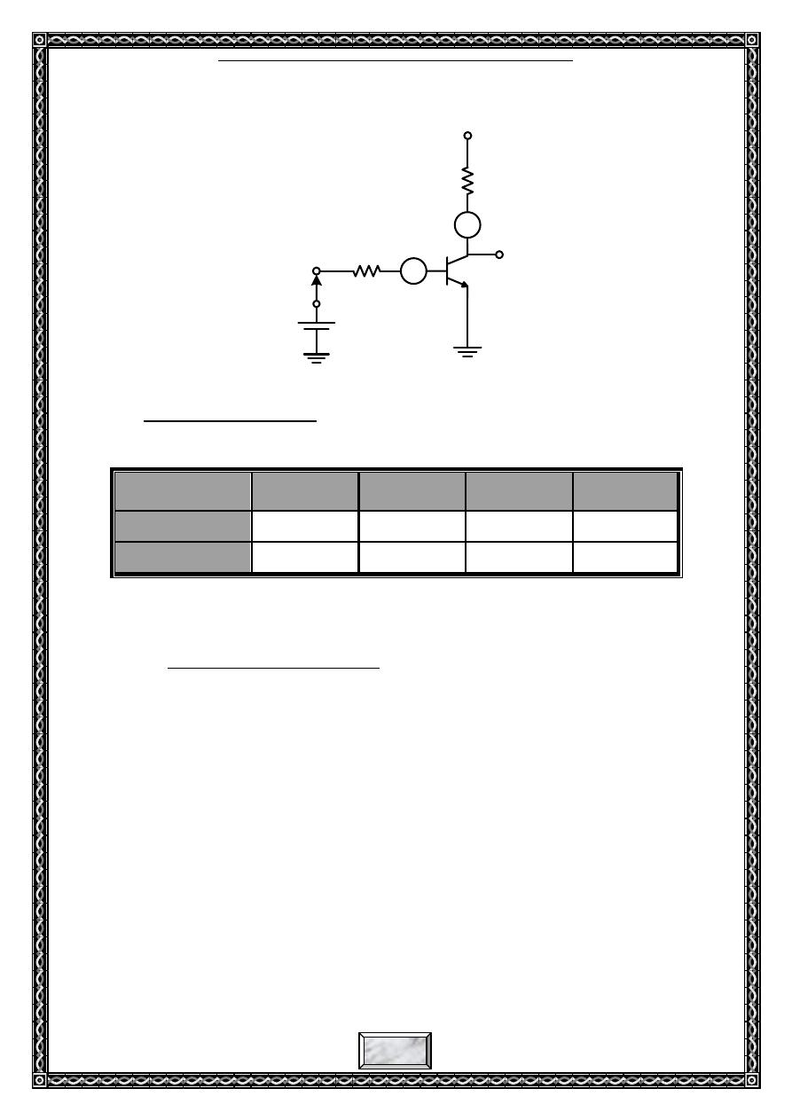
1-1 Experiment Procedures:
(1) Insert the short-circuit clip by referring to Fig. 6.
(2) Connect ammeter to measure I
B
and I
C
.
(3) Feed 5V voltage to the input terminal, then view I
B
, I
C
and V
CE
, and
make records in table -1.
(4) Disconnect voltage from the input terminal, then view I
B
, I
C
and V
CE
,
and make records in table -1.
Experiment (7): Transistor as a Switch & a Device Driver
5
2015/2016
12V
Q3
R17
2.2K
R15
22K
A
V
o
A
V
in
5V
Fig .6
1-2 Experiment Result:
Record in Table -1.
Table -1
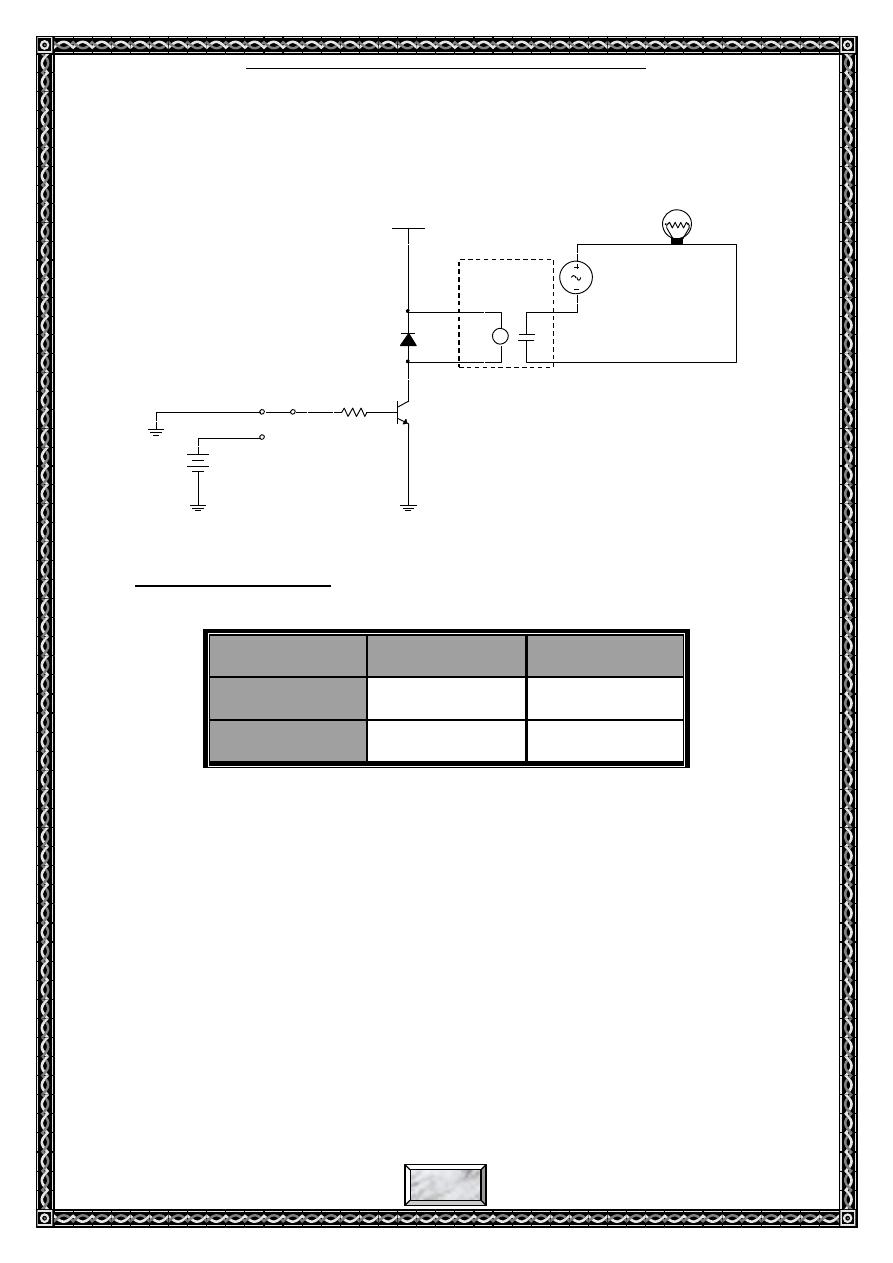
Item Two (2): Use transistor to drive a relay (Using Multi-Sim)
2-1 Experiment Procedures:
(1) Connect the circuit shown in Fig. 7 using Multi-Sim Program. you can find
the main devices of this circuit in the following Multi-sim libraries:
Relay from (Basic library/Relay/EDR201A05).
120V 60Hz AC Source from (sources library).
120V_100Watt Lamp from (indicators library/Lamp).
Switch from (Basic library/switch/SPDT).
(2) a. By using the switch (in the input of the circuit), feed 5V voltage to the
input terminal, then view if the lamp is illuminated (this means that the
relay has been turned on (magnetized)), use voltmeter to measure V
CE
and V
BE
.
Operating Region
of Transistor
V
in
I
B
I
C
V
CE
Saturation
Cut-off
Experiment (7): Transistor as a Switch & a Device Driver
6
2015/2016
b. Disconnect voltage from the input terminal, and then view if the lamp is
turned off (this means that the relay returns to OFF) )), use voltmeter to
measure V
CE
and V
BE
.
Fig. 7
2-2 Experiment Result:
Record in Table -3.
Table -2
Relay
V
BE
V
CE
ON
OFF
VCC
12V
Q2
2N2222A
K
K2
EDR201A05
1
V1
120 V
60 Hz
0Deg
X1
120V_100W
R1
22.1k
J1
Key = Space
V2
5 V
D1
1BH62
Relay
Experiment (7): Transistor as a Switch & a Device Driver
7
2015/2016
Conclution:(
)االستنتاج
Discussions:
(1) Explain at what conditions the transistor operate as a switch and as a driver.
(2) When the transistor drives a coil, why we must connect a diode in parallel with
the coil?
(3) choose the correct answer:
a) When the transistor works as a switch, it represents:
1. Amplifier
2. NOT Gate
3. Buffer
b) In saturation, the transistor ideally behaves like an closed switch between:
1. Base and Emitter
2. Base and Collector
3. Collector and Emitter
c) In cutoff, the parameter that will be in its maximum value is:
1. V
CE
2. I
C
3. I
B
d) To saturate a BJT,
1. I
B
= I
C(SAT)
2. I
B
> I
C(SAT)
/β
3. I
B
= 0
e) If base-emitter junction is open, the collector voltage is:
1. V
CC
2. 0V
3. Floating