
Continue - Application of
Combinational Logic Circuit /
DECODER- ENCODER
& Bit Converters
First Class
1
Dr. AMMAR ABDUL-HAMED KHADER
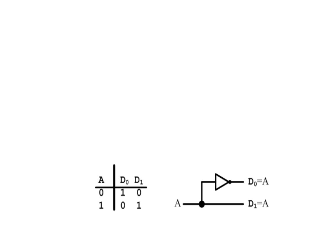
Decoder
• Decoder – Is a digital circuit that detects the presence of a
specified combination of bits (code) on its input and indicates
the presence of that code by a specified output level.
• Decoding – Is the conversion of an
n
-bit input code to an
m
-
bit output code with n ≤ m ≤ 2
n
such that each valid code
word produces a unique output code
• Circuits that perform decoding are called
decoders
• This a 1-to-2 Line decoder – exactly one of the output lines
will be active.
Dr. AMMAR ABDUL-HAMED KHADER
2
-
Decoder
Dr. AMMAR ABDUL-HAMED KHADER
3
X= A
3
A
2
A
1
A
0
- -
X= A
3
A
2
A
1
A
0
- -
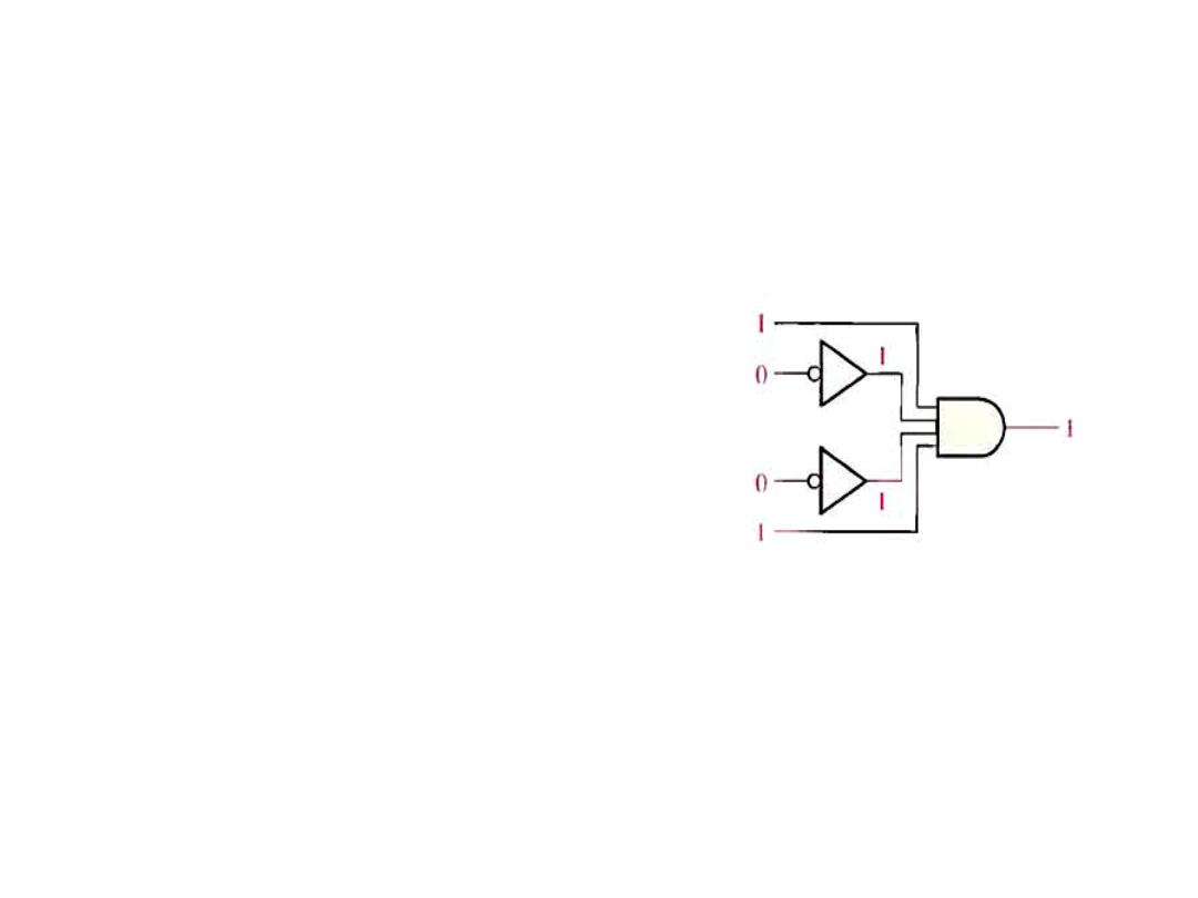
Example: Determine the logic
required to decode the binary
Number 1001 by producing a
High level on the output
Solution: You must be sure that
all of the inputs to the AND gate
are
HIGH
when
the
binary
number 1001 occurs,
Decoder
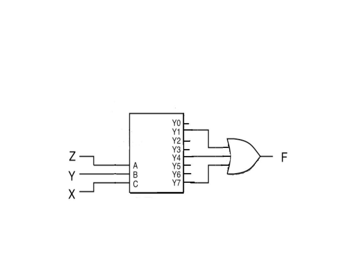
• Example: Realize F (X,Y,Z) = Σ (1, 4, 7) with a decoder
Solution: 1, 4, 7 means the three outputs obtained from eight
output.
Dr. AMMAR ABDUL-HAMED KHADER
4
0
1
2
3
4
5
6
7
Decoder
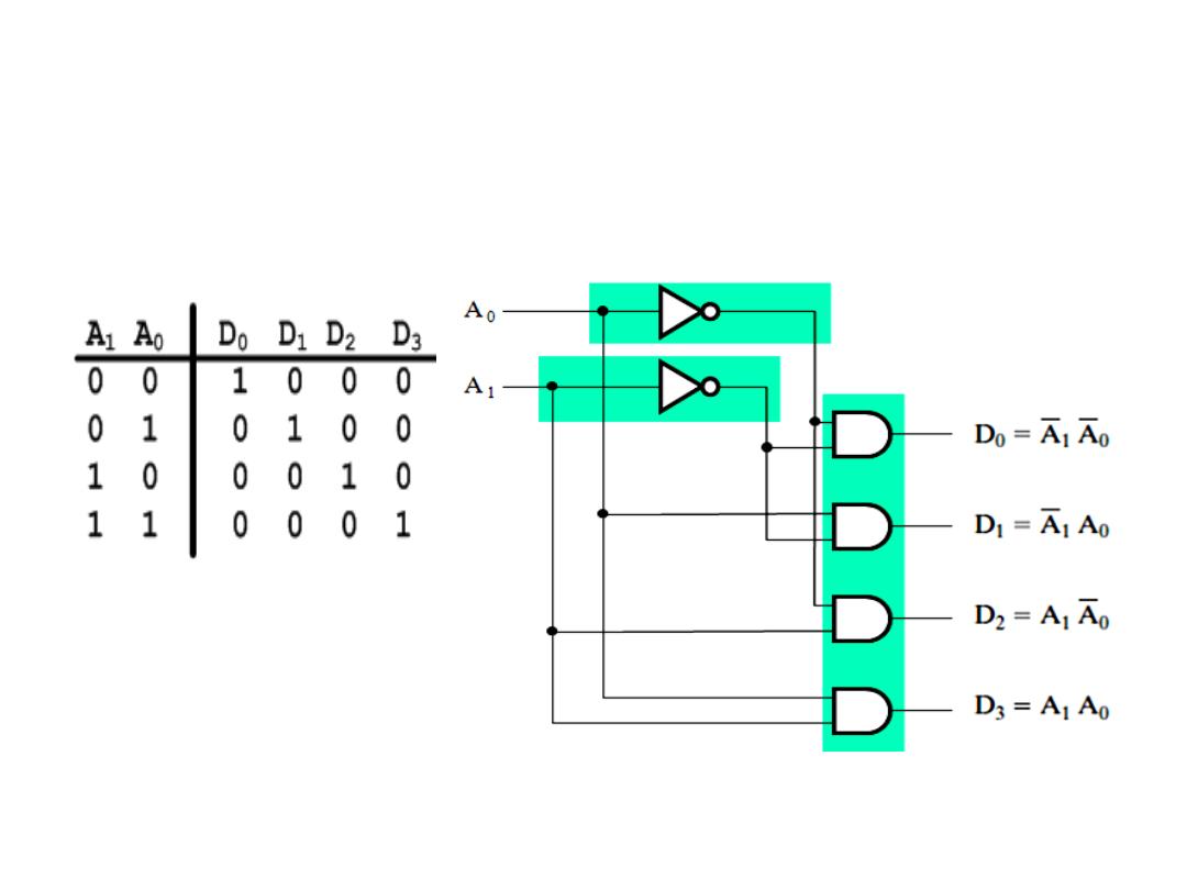
• A 2-to-4 line decoder
Dr. AMMAR ABDUL-HAMED KHADER
5
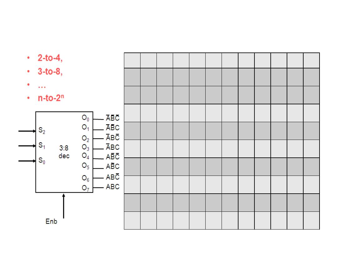
Decoder
Dr. AMMAR ABDUL-HAMED KHADER
6
A
B
C
E
nb
A
B
C
O
0
O
1
O
2
O
3
O
4
O
5
O
6
O
7
0
x
x
x
0
0
0
0
0
0
0
0
1
0
0
0
1
1
0
0
1
1
1
0
1
0
1
1
0
1
1
1
1
1
0
0
1
1
1
0
1
1
1
1
1
0
1
1
1
1
1
1
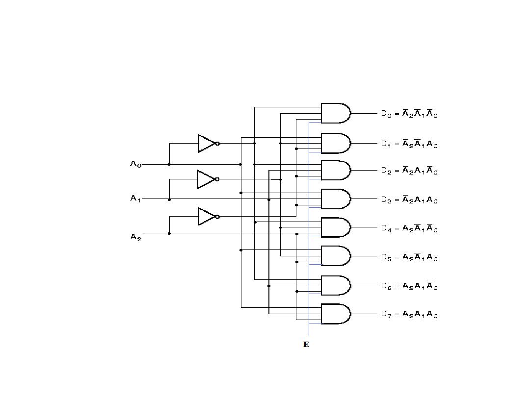
3-to-8 Decoder with Enable
Dr. AMMAR ABDUL-HAMED KHADER
7
Application of Decoder
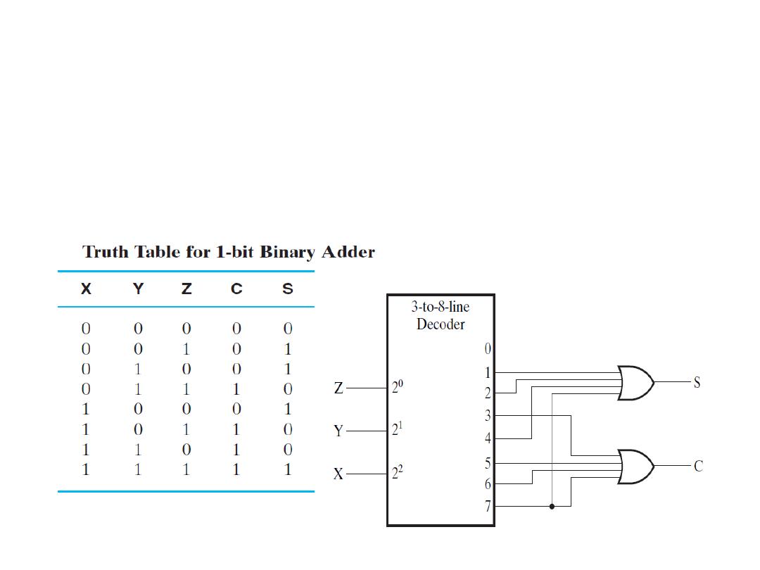
• Example: Realize the 1 bit-binary adder circuit using decoder.
Solution: The truth table is as shown, so the output function
should be:
Dr. AMMAR ABDUL-HAMED KHADER
8
)
7
,
6
,
5
,
3
(
)
,
,
(
)
7
,
4
,
2
,
1
(
)
,
,
(
m
Z
Y
X
C
m
Z
Y
X
S
Application of Decoder
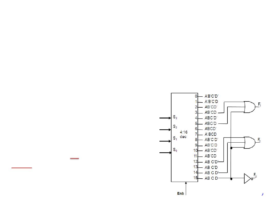
• Implementing General Logic
Any combinational circuit can be constructed using decoders
and OR gates!
Example: design a circuit that can realize the output below:
Solution:
Note: X’ means X
Dr. AMMAR ABDUL-HAMED KHADER
9
F1 = A' B C' D + A' B' C D + A B C D
F2 = A B C' D' + A B C
F3 = (A' + B' + C' + D')
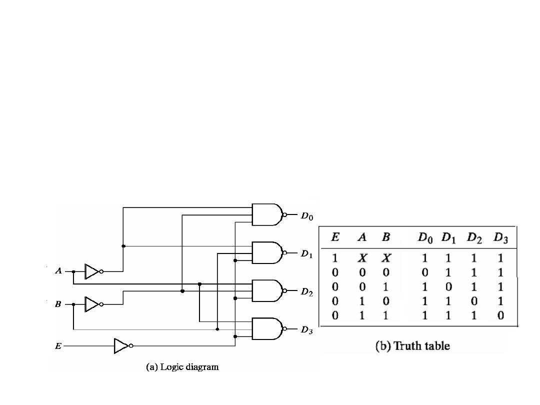
Active Low Decoder
• If an active-low output is required for each decoded number,
the entire decoder can be implemented with NAND gates and
inverters.
• Example: 2-to-4 Decoder is enabled when E=0 and an output
is active if it is 0
Dr. AMMAR ABDUL-HAMED KHADER
10
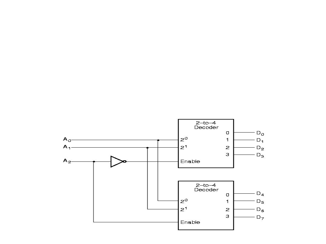
Decoder Expansion
Decoder expansion
• Combine two or more small decoders with enable inputs to form
a larger decoder. 3-to-8-line decoder constructed from two 2-to-
4-line decoders
• The MSB is connected to the enable inputs
• if A
2
= 0, upper is enabled; if A
2
=1, lower is enabled.
Dr. AMMAR ABDUL-HAMED KHADER
11
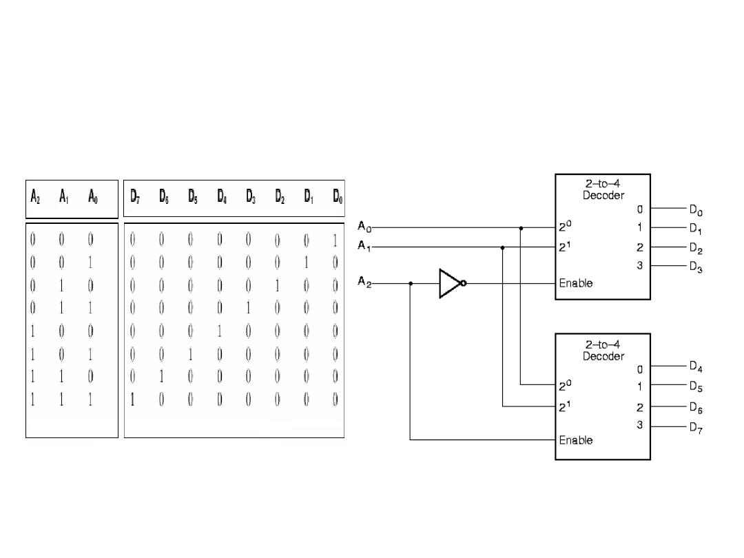
Combining Two 2-4 Decoders to Form
One 3-8 Decoder Using Enable Switch
Dr. AMMAR ABDUL-HAMED KHADER
12
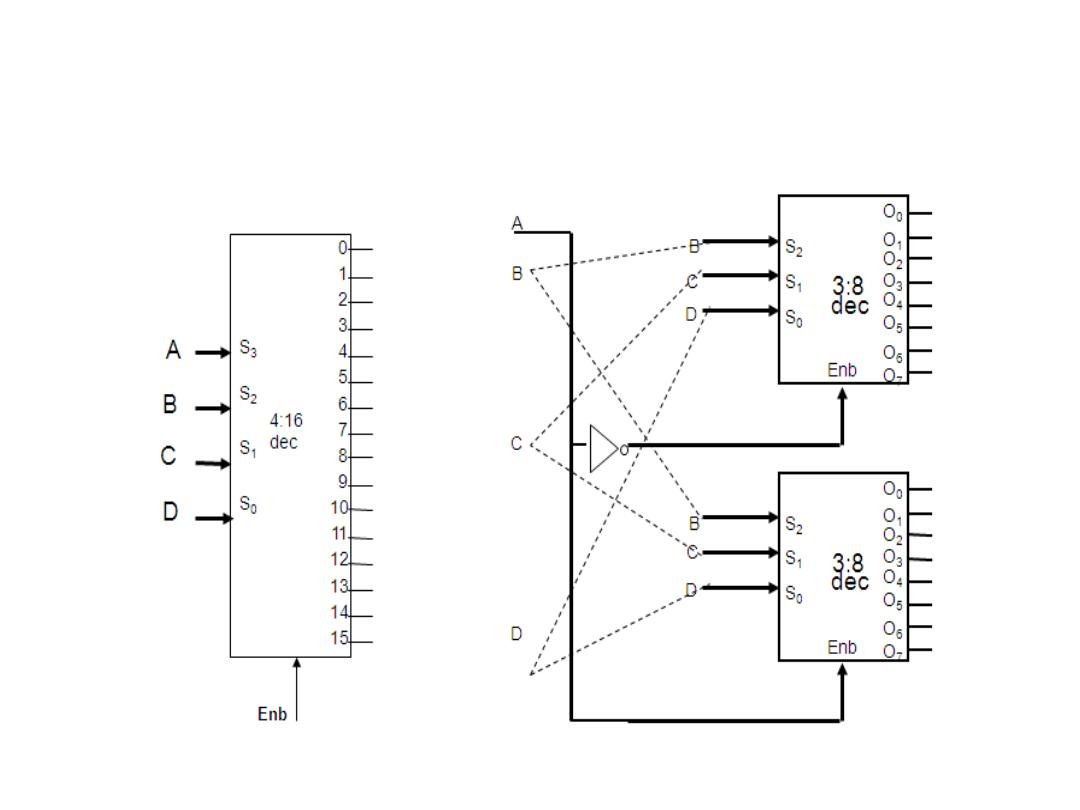
Combining Two 3-8 Decoders to Form
One 4-16 Decoder Using Enable Switch
Dr. AMMAR ABDUL-HAMED KHADER
13
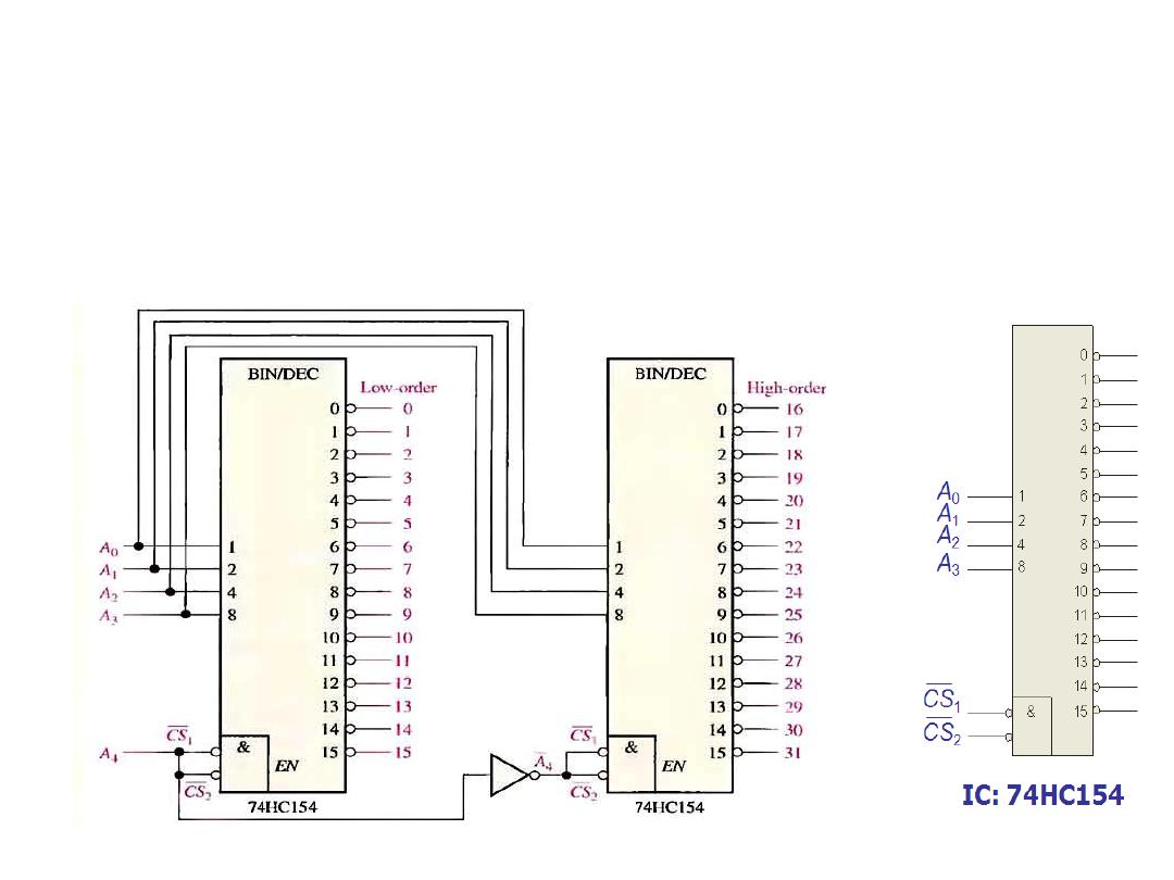
74HC154 Integrated Circuit
• Example: A certain application requires that a 5-bit number be
decoded. Use a 74HC154 IC decoders to implement the logic.
• Solution: Since this IC handle only 4-bits, two decoder must be used.
Dr. AMMAR ABDUL-HAMED KHADER
14
Chip
select
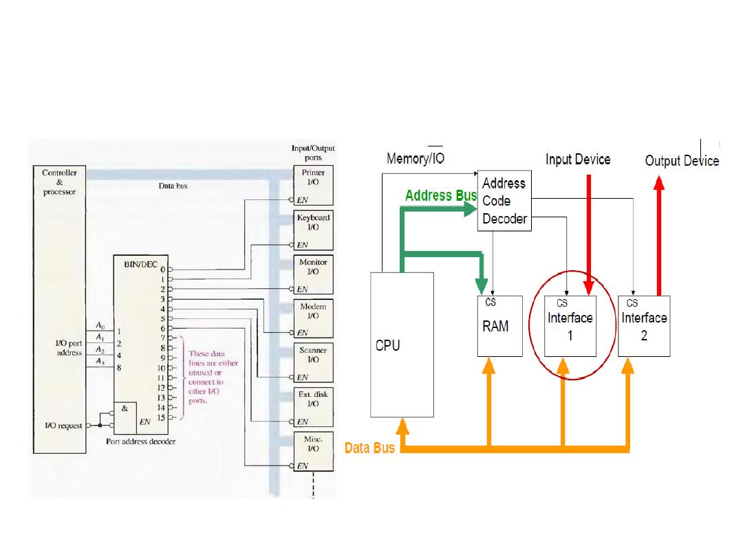
Application of Decoder in Computer
Dr. AMMAR ABDUL-HAMED KHADER
15
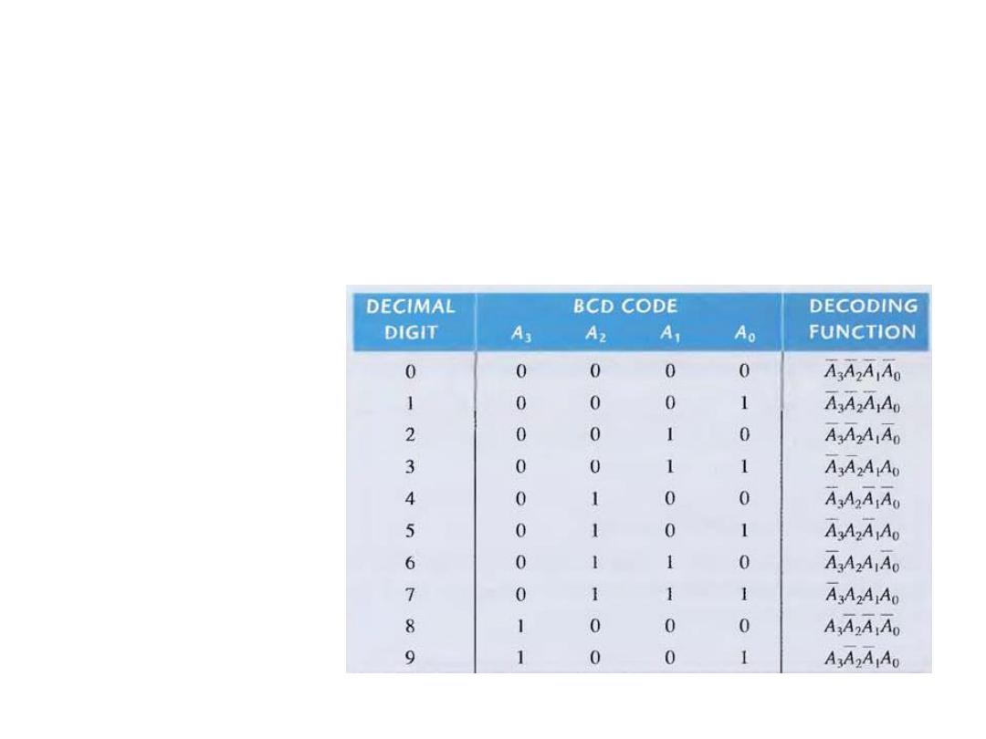
The BCD to Decimal Decoder
• It convert each BCD (8421 code) into one-to-ten possible
decimal digit indications. It is called 4-to-10 line decoder or a
1-to-10 decoder.
Dr. AMMAR ABDUL-HAMED KHADER
16
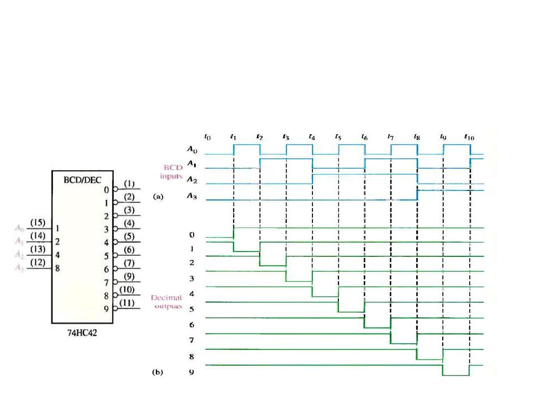
The BCD to Decimal Decoder
• Example: the 74HC42 is an IC BCD-to-decimal decoder. If the
input waveforms as in Fig. are applied to the IC inputs, show
the output waveforms.
Dr. AMMAR ABDUL-HAMED KHADER
17
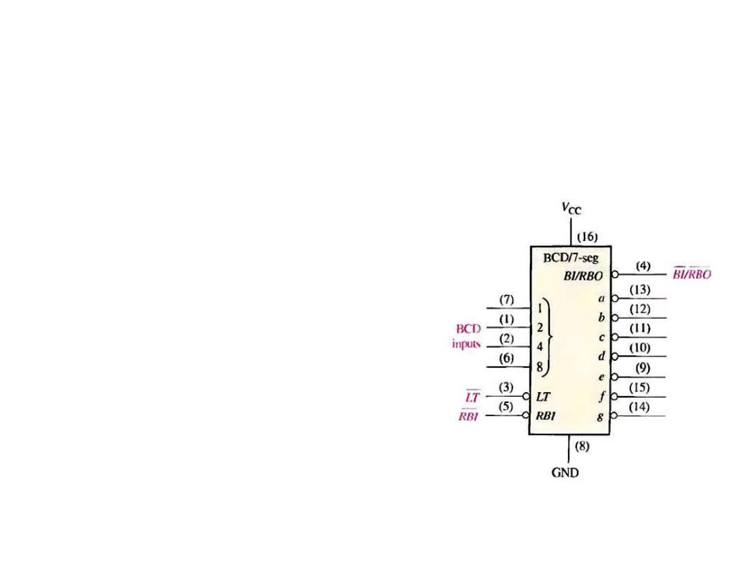
The BCD to 7-Segment Decoder
• This decoder accept the BCD code on its input and provides
outputs to drive 7-segment display devices to produce a decimal
readout.
• As an example, the 74LS47 . LT (Lamp
Test), RBI (Ripple Blanking Input),
BI/RBO (Blanking Input/ Ripple
Blanking Output). All output are non-
active (HIGH) if (0000) is on inputs
and if RBI is low. This causes the display
to be blank and produces a LOW RBO.
Dr. AMMAR ABDUL-HAMED KHADER
18
Encoder
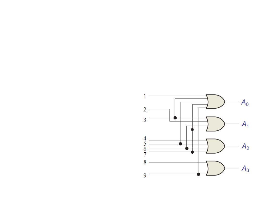
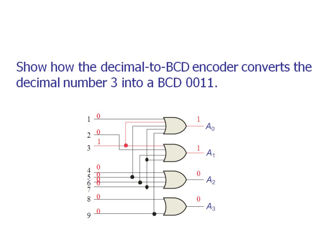
• An encoder is a combinational logic cct. that essentially
performs a reverse decoder function. It is accepts an active
logic level on one of its inputs representing a digit, such as a
decimal or octal digits, and converts it to a coded output, such
as BCD or binary.
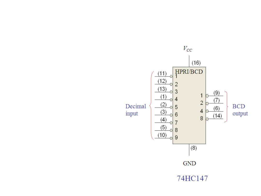
• IC: 74HC147 16-to-4 encoder
(decimal-to-BCD)
• IC: 74F148 8-to-3 encoder
Dr. AMMAR ABDUL-HAMED KHADER
19
Encoder
Dr. AMMAR ABDUL-HAMED KHADER
20
Encoder
Dr. AMMAR ABDUL-HAMED KHADER
21
The 74HC147 is an example of an
IC encoder (Decimal-to-BCD). It
has ten active-LOW inputs and
converts the active input to an
active-LOW BCD output.
Code Converters
Dr. AMMAR ABDUL-HAMED KHADER
22
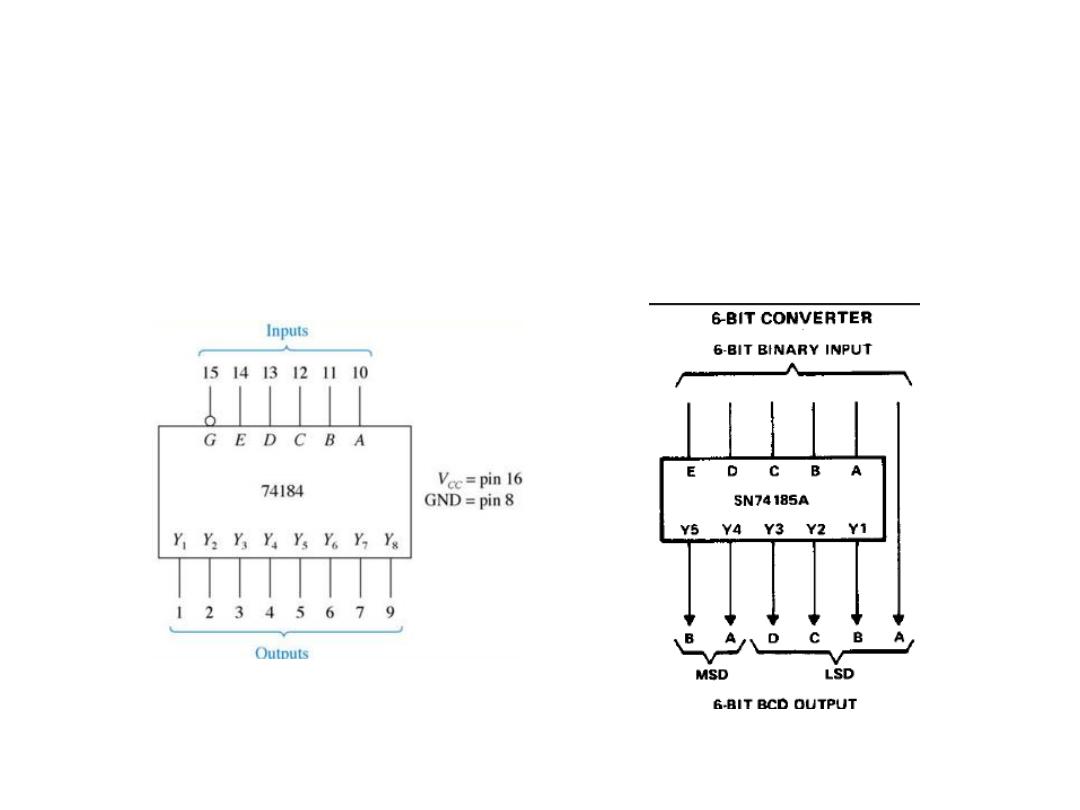
• BCD-to-Binary Conversion
• IC: 74184
• Binary-to-BCD Conversion
• IC: 74185
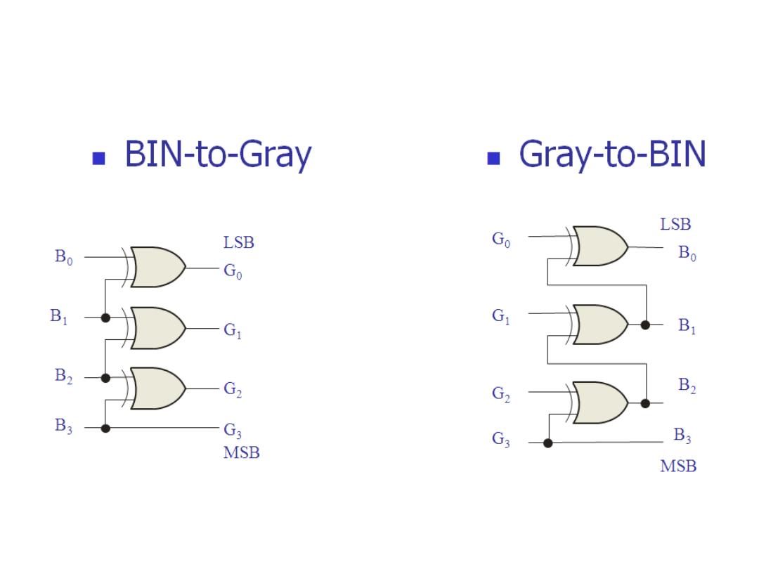
Code Converters
Dr. AMMAR ABDUL-HAMED KHADER
23
