Experiment No. (7)
Encoder Circuit
Study Objective:
Understanding the construction and operating principles of encoder circuits.
Introduction:
Encoder circuit
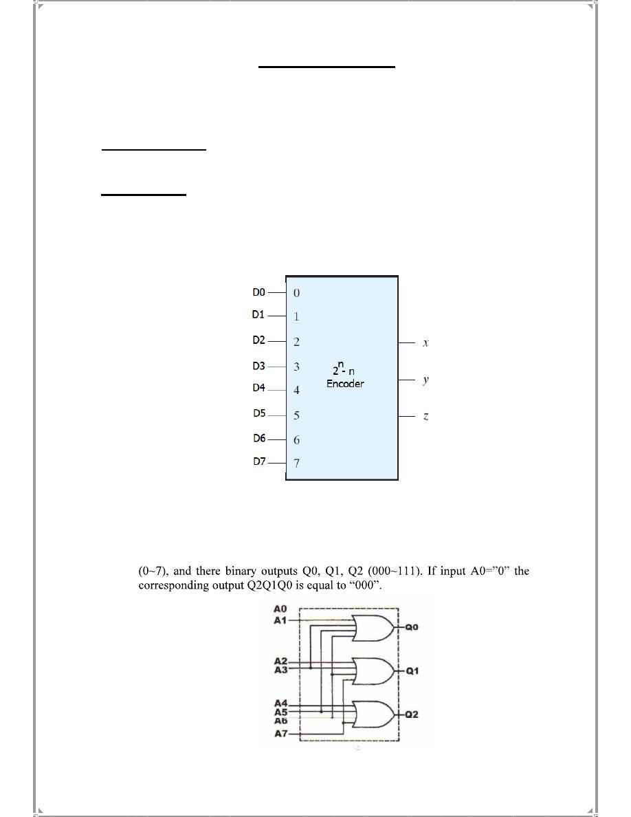
An encoder is a combinational logic gate that accepts multiple inputs and
generates a specific output code when only one input is triggered at a time. An
encoder with 2
n
bit inputs and n-bit outputs is shown in the figure below .
Octal
to
binary
Encoder
An
octal
to
binary
encoder
is
shown
in
figure 7-1.
There
are
8
octal
inputs
A0~A7
Fig.7-1
Experiment Equipments:
(1) KL-31001 Digital Logic Lab.
(2) Experiment Module: KL-33005, KL-33006.
Experiment 1:
Constructing a 4-to-2 Encoder with Basic Gates
Experiment Procedures:
(1)
Insert connection clips according to Figure 7-2.
Fig.
7-2
If two inputs are triggered at the same time, the output will be incorrect. To solve this
problem, encoder circuits must establish an input priority to ensure that only one input
is encoded.
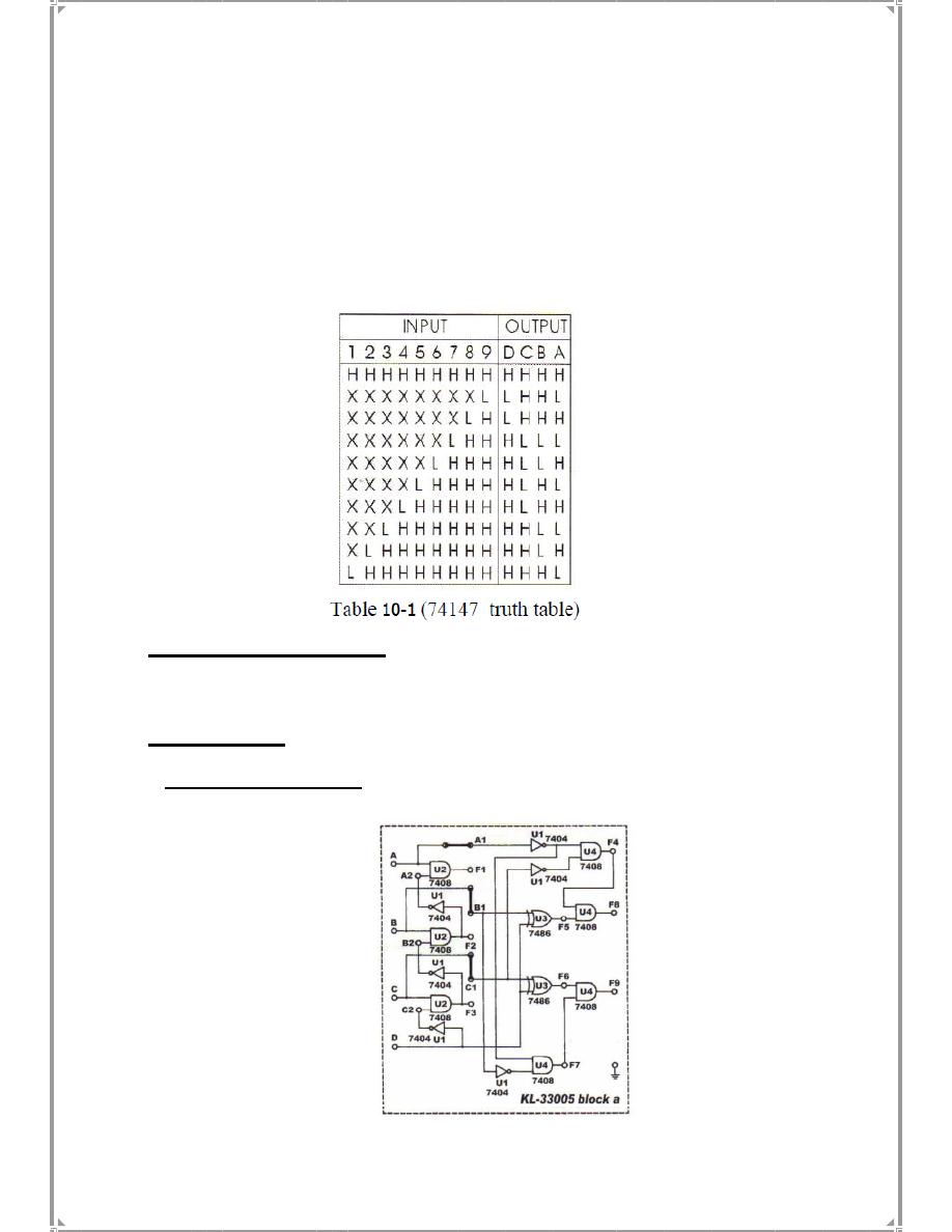
The 74147 IC is an active
low
9-4 priority
BCD
output
encoder.
When
inputs
1~9
are
all
in
high
state ,
output
DCBA = “HHHH ”. When input 2 and 5 are triggered
simultaneously the output
is
determined
by
input
5,
which
has
higher
priority
than
input
2.
When
inputs
2,
5
and
7
are
triggered
together ,
input
7
will
determine
the
output.
(2) Connect Vcc to +5V.
(3) Connect inputs A~D to Data Switches SW3~SW0 respectively; outputs F8
and F9 to logic Indicator L0 and L1.
(4) Follow the inputs sequences for
A
,B,C,D in Table7-2
and
record
the
output
states.
Table 7-2
A
B
C
D
F9 F8
0 0 0 0
0 0 0 1
0 0 1 0
0 0 1 1
0 1 0 0
0 1 0 1
0 1 1 0
0 1 1 1
1 0 0 0
1 0 0 1
1 0 1 0
1 0 1 1
1 1 0 0
1 1 0 1
1 1 1 0
1 1 1 1
Fig. 7-3
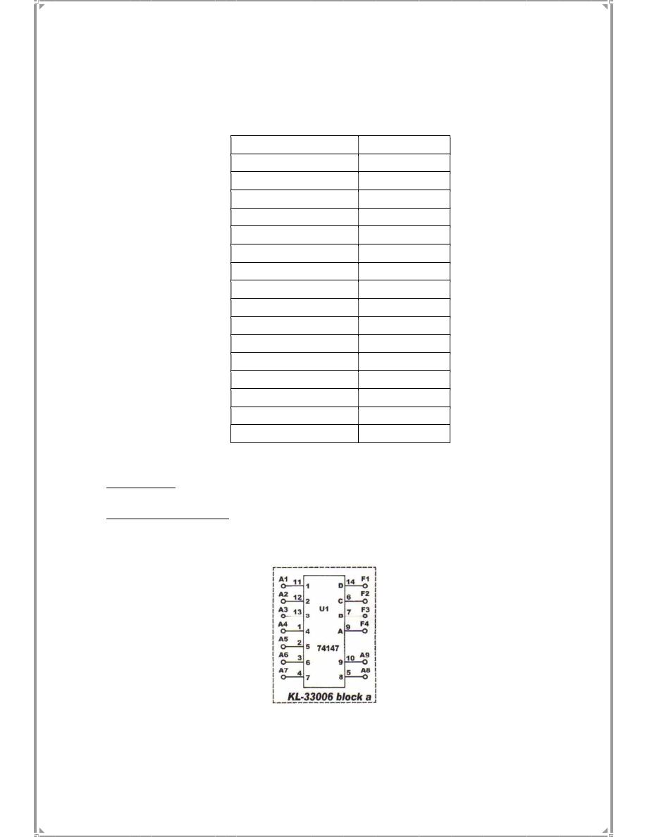
(2) Connect inputs A1~A9 to DIP Switches 1.7~1.0, A9 to 2.0. Connect outputs
F1~F4 to logic indicators L4~L1. Follow the input sequences given in Table 7-3
and record output states.
Experiment 2: 9-4 Encoder with TTL IC
Experiment Procedures:
(1) The 74147 (U7) on block a of module KL 33006 is used in this section of the
experiment. Connect Vcc to +5V.
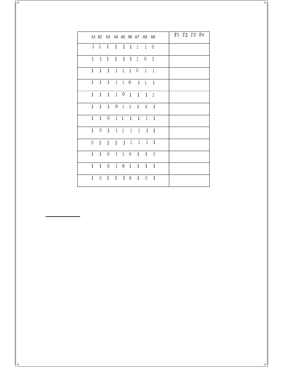
Table
7- 3
Discussions:
1. Which statement is true for a priority encoder that has two inputs triggered at the
same time?
a. The output will be incorrect.
b. The output is determined by the input with higher priority.
c. The output will remain correct.
2. Derive the output Boolean function (F9, F8) of the circuit shown in figure 7.3.
3. Validate the Boolean expression derived above in (2) using the truth table.
4. Which of the statement is true for the 74147 Encoder shown in figure 7.
3?
a. It has an active low input & active high output
b. It has an active low input / output
c. It has an active high input & active low output