Step By Step Construction Of
Orthodontic
Removable Appliance
Lab-work Handout for year 4 students at The
University of Mosul / College of Dentistry.
2018
Authors
:
Dr.Anas Almukhtar
B.D.S., M.Sc. Ph.D Orthodontics
Dr. Ne`am Fakhri Yassin
B.D.S., M.Sc., Ph.D Orthodontics

1

2
List of contents
LAB:1. INTRODUCTION ......................................................... 6
LAB:2. THE PALATAL FINGER SPRING ........................... 11
LAB:3. MODIFIED FINGER SPRING ................................... 17
LAB:4 . Z-SPRING ................................................................... 21
LAB:5 DOUBLE Z-SPRING .................................................. 26
LAB:6. T- SPRING .................................................................. 30
LAB:7. THE BUCCAL CANINE RETRACTOR .................. 34
LAB:8. MODIFIED BUCCAL CANINE RETRACTOR ..... 38
LAB:9. ADAM'S CLASP ........................................................ 42
LAB:10. THE LABIAL ARCH ................................................ 47
LAB:11. THE FITTED LABIAL ARCH . ................................ 51
LAB:12. ROBERT'S RETRACTOR ........................................ 54
LAB:13. ACRYLIC BASE PLATE ….. ................................... 58

3

4
List of figures
. ...................................................... 11
..................................... 16
.................................... 20
. ........................................................... 25
. ................................................... 29
................................................................... 33
.. ........................ 34
........................................................... 46
......................................................... 50
............................................... 53
................................................ 57
............................................................ 63
.. ......................................... 64

5

6
Lab:1. Introduction
.
Orthodontic Removable Appliance:
An orthodontic appliance that could be inserted and
removed by the patient.
In general, Removable orthodontic appliances are
considered as an interceptive orthodontic treatment and
is mostly used in mix dentition period. Basically, they
either resolve the treated dental problem or diminish its
severity. Either way, this is definitely beneficial to the
patient. However, this is a patient-dependent protocol
and stability of the appliance in place is vital. The
stability is accomplished mainly by retentive components
(clasps) attached to the appliance. Fulfillment of the
treatment objectives requires a substantial mechanical
concept and designing.
Biomechanics of Tooth movement
When a force is applied to the crown of a tooth, it
will displace slightly within the confines of the
periodontal ligament. This small change in position will
set up areas of tension and compression within the
periodontal ligament. Provided that the force is applied
over a sufficient period of time, remodeling of the socket
will allow the tooth to move farther.
Types of tooth movements:
1. Spontaneous tooth movement: include tooth
movements that occurs spontaneously without
orthodontic force application, An example of this is

7
tipping toward an extraction space or over eruption
of teeth opposite to an extracted tooth.
2. Active tooth movement: these movements which
occur due to application of orthodontic force to the
crown of the tooth. Active tooth movement could be
sub-categorized into the following:
a. Tipping Tooth Movement: When a force is
applied at a single point on the crown trying to
move the tooth, the alveolar bone will resist that
movement which will result in tipping of the tooth
around its center of rotation (about 40% of root
length apically). This means that while the crown
moves in one direction the root apex will move in
the opposite direction.

8
b. Translation (Bodily) Tooth Movement: When all
parts of the tooth move in the same direction for the
same distance. If a tooth is to be moved bodily, a
force couple must be applied to the crown in
conjunction to the original force. This is not
practically applicable with removable appliance
since it is difficult to control the M/F ratio along the
course of tooth movement.
c. Intrusion and Extrusion tooth movement: Is a
translational movement parallel to the long axis of
the tooth.
d. Rotational movements: Rotation of the tooth
around its long axis. To achieve this type of tooth
movement, the application of couple force is
required.
Construction of removable appliance
Removable appliances are made in dental laboratories.
However, learning the basic construction techniques is
essential to master the various applications and mode of
action of each of the components.
Components of removable appliance:
1. Active components: The active components are used
for the application of orthodontic force to the teeth
and are made mainly from stainless steel wires and
Screws and elastics are also used in removable
appliance but less frequent. An example is the Z
spring.

9
2. Retentive components: Those components that are
used to provide resistance of the dislodgement of the
appliance from the mouth. For example of that are
different types of clasps labial bows.
3. Acrylic base plate: Is the basic frame to which all
active and retentive components are attached directly
or indirectly. In addition to its function as the main
frame it also plays an impotent role as an active
component. for example when modified as an anterior
bite plate to treat deep bite cases, also considered as
an impotent retentive component as its adaptation to
the palate and the engagement to the palatal undercuts
of the molars and premolars will increase the retention
of the appliance.
Essential construction tools
For the vast majority of removable appliances the
usual set of instruments and materials are composed of:
1. Orthodontic pliers and cutters
Orthodontic pliers
These are used for all wire bending. The ends are
firm, tapered, with one round end and the other
pyramidal or 2 rounded in section, and meet only at the
tips. The beaks meet only at the tips so that they are
separated about O.6 mm at the base when the pliers are
closed. This makes the beaks of the Universal pliers
parallel when gripping the wire.
Tow famous pliers of this type are:
a) Angle pliers (coil forming pliers): with one cone-
shaped beak and one pyramidal beak.

10
b) Adams pliers (universal pliers): with two
pyramidal beaks.
Orthodontic wire cutters
The diagonal type of wire cutter is used and must have
hardened blades.
2. Stainless steel wire;
These are used to make the active and retentive
components. they can be classified according to its
hardness to:
Extra-hard
Hard (used in removable appliances)
Soft
The wires gauge range between 0.3-1.5 mm; in
removable appliances we use 0.5 - 0.7 mm hard stainless
steel wire.
3. Acrylic:
This is used for construction of the frame or the body of
removable appliance that carry the active and passive
springs. Chemical cure, light cure or hot cure acrylic
could be used. Colures and additives are preferable.
4. Patient’s dental cast model:
A pair of dental cast model (upper and lower arches) for
the patient should be present when constructing the
removable appliance. These are necessary for treatment
plan and construction of the appliance.
11
Manual training:
The students are instructed to make the following shapes
(Figure: 1) using 0.6 or 0.7 stainless steel wire.
Meanwhile instructions about the correct pliers grasping,
wire bending and cutting are being given.
Those shapes will introduce the student to the manual
skill of wire bending and help him/her to manage future
wire works accurately.
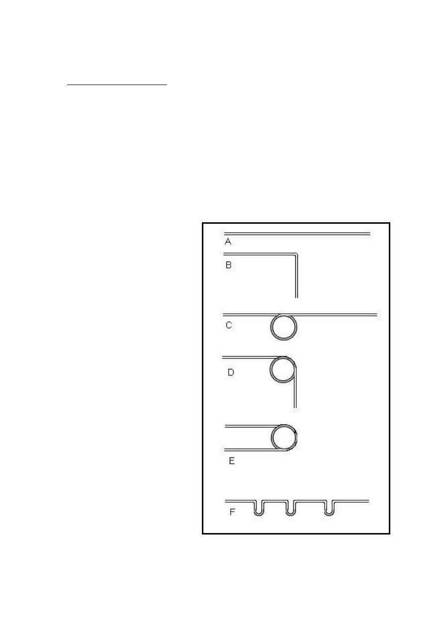
Figure
1 the students are
instructed to make the shapes
of : A. Straight wire piece;
B. 90 degree angle; C.
Straight wire with coil; D. 90
degree angle with coil; E.
Full turn coil; F. three well
aligned vertical loops on the
same wire.

12
Lab:2.
The palatal finger spring
Description and design
The simplest form of this spring is a strait piece of
wire embedded at one end in the acrylic base plate. The
usual wire diameter is 0.5 mm or occasionally 0.6 mm. a
coil is incorporated near the point of insertion into the
acrylic, this increase the length of the wire and stores
activation energy, thus, it will help delivering a light
force over a longer range of action (figure:2A). The coil
should be made as large as possible 3- 4mm . It is placed
so that when activated it is tightened (the coil is placed
on the side away from the desired tooth movement).
A coil spring of this design will usually be about 2
cm in length from the point of force application to the
insertion into the acrylic. The position of the coil
(distance from the tooth) is most important as it influence
course of action in which the spring works.
Indications:
It is commonly used to move any tooth mesially or
distally along the dental arch
Advantages:
1. Simple design
2. Provide light pressure
3. Well tolerated by the patient
4. Several springs can be added if required
Disadvantages:
- The palatal finger spring can not move teeth in
labial or palatal directions.

13
Step by step construction of finger spring
1. With a sharp pencil, sketch the design of the wire on
the cast model according to the (description and
design) mentioned above.
2. Cut a (5cm) of ( 0.5mm) round stainless steel wire
3. straighten off the wire piece
4. Make a very small loop ( as small as possible) at one
end of the wire and then bend it to be ( 90° )to the
spring long axes. This will be the tooth end of the
spring and will help tooth engagement and prevent
injury from sharp wire terminal.
5. Adapt the wire on the cast model so that the tooth end
is fit on the tooth side opposite to the direction of the
desired tooth movement and the spring long axes is
perpendicular on the direction of tooth movement.
Then measure about (*15 mm) from the tooth end of
the wire and put a mark on the wire.
6. Hold the wire on the mark. The round beak of the plier
should be held away from the operator and from the
first bend made on the wire,( keep in mined that the
coil will always be away from the direction of the
desired tooth movement). Start rolling over the wire
around the round beak of the pliers until forming a
complete coil, and the wire continues in the same
direction.
7. Make sure that the coil will be above the tooth end
(active arm) of the spring. This is a critical point of the
wire design since it will keep the active arm close to
the palate.
Please note that this section is for training purpose only and the
construction steps are not required in any written or verbal exam.

14
8. Re-adapt the spring on the cast model and check the
following points:
a) The spring fits on the side of the tooth away from
the direction of tooth movement
b) The coil is on the side away from the direction of
tooth movement
c) The coil is above the active arm
9. Leave about (4mm) from the coil end and mark the
wire. This is the point where the wire will start to be
embedded in the acrylic.
10. About (2mm) after this point, make a (45°) bend on
the round beak of the pliers and start a 2 to 3 ( zigzag )
bends that is the retentive part of the wire which will
provide the mechanical retention of the spring in the
acrylic base-plate.
11. Cut the excess of the wire and adapt it on the cast
model with piece of soft wax. and check the fallowing
points:
a) The length of the spring is about 2 cm from the
tooth end to the point of insertion into the acrylic.
b) The retentive zigzag does not cross the midline to
the opposite side.

15
Boxing, Open spring and Wire guard:
These are three designs of the acrylic base plate
around the finger spring. Boxing (figure:2B) is designed
to provide the freedom of movement of the active arm
and coil inside an acrylic chamber built in the base-plate.
Open spring (figure:2C) is designed to completely
remove the acrylic of the base-plate from the path of the
movement and leave the active arm and the coil free
without protection. Wire guard is the addition of a
stainless steel wire be incorporate in the open spring
design to prevent distortion of the spring during wearing
and activation. This could be from the tongue side or
occasionally from palatal side too. It could also be used
with the boxing design palatally for the same reason.
Those three designs will be discussed thoroughly in base
plate construction labs.
Activation
It is widely believed that for a single rooted tooth a
force of 30 to 50 g is enough to produce orthodontic
tooth movement with minimal tipping. A tension gauge
could be used to measure the force; however the usual
activation is roughly one third to one half of a unit (the
mesio-distal dimension of the tooth). This is about 3-5
mm. Over activated springs may be harmful to the tooth
producing pain and discomfort to the patient (figure:2).
The palatal finger spring is activated by gentile
opining of the coil with the use of angle pliers the old
position of the tooth end of the spring (before activation)
is marked on the base plate to be compared to the new
position (after activation).
16
A B
C D
Figure
2 the palatal finger spring. A: palatal figure spring design ; B: boxing with wire guard ;
C: open spring ; D: activated finger spring.

17
Lab:3.
Modified finger spring
One of the modifications to the palatal finger spring
is the modified finger spring. it differs from the original
one in four main points: Its action is applied labially
rather than palatally; It crosses the occlusal surface; The
direction of force is vertical and it needs an attachment
(usually orthodontic bracket ) on the labial surface of the
tooth in order to apply its action ( figure 3).
The gauge of the wire is 0.5mm or 0.6mm, a loop is
incorporate in the wire design to increase the length of
the wire and its range of action.
Indications:
For extrusion for ectopic or high buccally erupted teeth
Advantages:
1. Simple design
2. Suitable range of action
Disadvantages:
3. Can not be boxed or guarded.
4. Subjected to distortion.
5. Trauma to the vestibular soft tissues.
Step by step construction
1. On the plaster model, sketch the wire design on the
labial gingiva (figure 3). The end of the active arm
Please note that this section is for training purpose only and the
construction steps are not required in any written or verbal exam.

18
usually located at the mesial margin of the target
tooth and extended distally passing over the tooth to
be moved in addition to two teeth behind. This will
be about 3 mm above the gingival margin. At that
point a small loop 3-4mm in diameter is constructed
by which the wire will change its direction
occlusally, crossing the occlusal surface at the
embrasure between the teeth and rolling over to the
palatal side of the arch where the spring ends by a
retentive zigzag form.
2. Cut about 7 cm of 0.5 mm round stainless steel wire
3. Straighten the wire piece
4. Start to form a very small loop at one end of the wire,
this will be the end of the active arm of the spring
and will prevent injury to the adjacent soft tissue
5. Adapt the wire to the curvature of the alveolar arch.
Fit the wire in position and put a mark on the distal
margin of the third tooth (according to the design
drawing).
6. Hold the wire with the pliers 2 mm behind the mark
point and start to form a 3-4mm loop. The direction
of the loop is always away from the tooth to be
moved (that’s mean the coil will try to open while it
is in action).
7. The coil will not take a complete turn and the wire
leaves the coil at aright angle to the direction of the
active arm and will be directed occlusally.
8. Fit the wire in position and check the following
points:
a. The length of the active arm is appropriate.
b. The lop is above the active arm.

19
c. The wire is adapted to the alveolar mucosa (
1mm away from mucosal surface).
d. The active arm runs 2-3 mm above the gingival
margin.
9. After the necessary correction have been made, Fit
the wire in position and put a mark on the occclusal
end of the embrasure where the wire will pass above
the occlusal surface of the teeth. And use the round
beak of the angle pliers to make a sharp turn to the
palatal side of the dental arch.
10. Adapt the wire on the palatal surface of the teeth
and mucosa
11. Start to make a retentive zigzag bends starting at
the point about 2mm after the lingual gingival margin
where the acrylic base plate will be located, and then
cut the excess wire.
12. Fit the wire in position and check the fallowing:
a. The wire does not interfere occlusally with the
opposing arch.
b. The spring does not cross the midline
c. The loop does not interfere with the vestibular
tissues.
13. Now to finish the spring a small bend is made on
the active arm
(about 10 degrees) at the distal margin of the targeted
tooth gingivally. This bend will ensure correct
direction of the applied force during the course of
action.
Activation:
Activation of the modified finger spring is made by
opining the coil so that the active arm will be about 3
20
mm occlusally to the passive position (figure: 3B). This
will deliver force of about 20-30g which is enough for
extrusion movement.
. A
B
3-4 mm
2-3 mm
3 mm
Figure
3 The modified finger spring( Basic design .A:basic design; B: Activation

21
Lab:4 . Z-Spring ( double cantilever)
This is a variant of the palatal finger spring and the
commonest type in this group.
Description:
The spring is bent into the shape of the letter ' Z '
with two coils each is (2 mm) in diameter. It should be
constructed with the spring compressed. The presence
of two coils makes it possible for the active end of the
spring to be activated in a straight line perpendicular
to the dental arch.
Indications
:
1. Correction of single palatally Positioned anterior
tooth.
2. Correction of simple rotation ( not more than 45° )
when combined with active labial arch to produce a
couple force.
Advantages
:
1. The spring is compact and may be narrowed to
small teeth such as lateral incisors.
2. The force is delivered in a straight line due to the
presence of two coils.
3. The spring could be boxed and distortion is not
common.
Disadvantages:
1. Not suitable for posterior teeth.
2. If the spring is made very small it can produce an
excessive force during activation.

22
3. The reactionary force from the cingulum tends to
displace the anterior part of the appliance, good
anterior retention is therefore essential.
4. May produce some intrusive force.
Step by step construction procedure:
1. Start sketching the design of the spring on the
palatal surface of the cast model. The spring name is
self explanatory as it will take the shape of the letter (
Z ) (figure: 4A). The spring is confined to the mesio-
distal dimension of the tooth to be moved. starting at
the mesial border of the tooth, draw a straight line 2-3
mm above the palatal gingival margin crossing the
tooth to the distal side, at that point a coil of 2 mm in
diameter is placed, make sure it will be confined to the
tooth borders, then continue the line in reverse
direction gingival to the coil till the mesial side of the
tooth, at that point another coil of the same dimension
is placed, also make sure that the spring is confined to
the mesio-distal dimension of the tooth, now continue
the line back in reverse direction gingival to the coil
passing about 2 mm ( nearly at the middle of the tooth
dimension where a sharp turn is made to change the
direction posteriorly , the line then continues straight
about 6 mm then start 2 to 3 zigzag retention form.
2. Take a (5 cm) piece of a (0.5mm) stainless steel wire
and straighten it.
3. Start by making a small loop ( as small as possible) at
one of the wires ends, this will be the active end of the
wire.
Please note that this section is for training purpose only and the
construction steps are not required in any written or verbal exam.

23
4. assuming that the z-spring is mad for the upper left
permanent incisor, put the wire on the palatal surface
of the tooth with the small loop is pointing mesially
and mark the point at the distal margin of the tooth.
5. Hold the wire about (1 mm ) before the mark point and
start forming the loop. The size of the loop is very
small in that the wire must be held at the very end of
the pliers beaks, makes sure that the coil is above the
active arm ( the wire end) this will facilitate the correct
direction of the applied force, make a complete turn
heading backward mesially.
6. Re-fit the wire in position and mark the mesial end of
the tooth (the mesial and distal end represents the
largest mesio-distal dimension of the tooth).
7. Repeat the coil just the same as the previous one except
that the coil here is above the remaining wire, this will
facilitate easier adaptation of the spring to the
curvature of the palate. Complete the turn so that the
remaining wire is pointed distally again. Make sure
that the two coils are at the same plain.
8. Re-fit the wire in position according to the sketching
and mark the wire about (2 mm) away from the second
coil (nearly at the meddle of the mesio-distal
dimension of the tooth).
9. Hold the wire just before the mark point and make a
90° bend (on the round beak) at the same plain with the
coils. This will leave the remaining wire pointing
backward.
10. Leave about (6 mm) and start a retentive zigzag
bends, then cut the remaining wire.
11. If the coils are loose and were opened during
construction, squeeze the spring i.e. close the coils to

24
the maximum is mandatory since it will increase the
range of action during the active treatment.
12. Now the spring is completed in shape but is parallel
on the tooth surface and not useful. The active part of
the spring must apply the force perpendicular to the
tooth long axes (figure 4B). This is made by a rounded
bend at the start of the (6mm) straight area of the
spring wire just after the 90 degrees bend; the direction
of the bend is toward the palatal surface which will
elevate the coils to be perpendicular to the tooth long
axes. This bend could be combined with the 90 degree
bend to produce the desired orientation.
13. Be aware that the tooth long axes is not the palatal
surface of the tooth, it is represented on the cast model
by an imaginary line passing between the labial and the
palatal tooth surface.
14. the spring is then boxed with wax ( same as in
finger spring ) and ready for the construction of the
acrylic base plate
25
Activation:
There are two methods for the activation of Z-spring
a. By opining the first coil or the second coil alone, it will
produce force at one side of the tooth which will try to
rotate it.
b. By opining both of the coils which is practically done
by gentile pulling of the active arm to produce
elongation of the spring about (2-3 mm). This is quite
enough for tipping movement and keeping the active
arm parallel to the tooth surface which will produce
equal force on both sides of the tooth.
A B
Figure
4 The Z spring A:Z- spring positioned on the lateral incisor ; B: the z-spring is
positioned perpendicular to the tooth long axes.

26
Lab:5 Double Z-Spring
.
This spring is simply tow Z-springs joined by their
active arms.
Description:
The spring is bent into the shape of two ' Z '
facing each other (figure:5) with four coils each one is
(2 mm) in diameter. It should be constructed with the
spring compressed and the presence of two coils on
each side of the spring makes it possible for the active
end of the spring to deliver the force in a straight
perpendicular to the dental arch.
Indications
:
1. Correction of up to four palatally Positioned anterior
teeth.
2. Correction of simple rotation ( not more than 45° )
when combined with active labial arch to produce a
couple force.
Advantages
:
1. The force is delivered in a straight line due to the
presence of four coils.
2. The spring could be boxed and distortion is not
common.
3. Used for correction of more than one tooth, (2-4)
anterior teeth at the same time.
Disadvantages:
1. Not suitable for posterior teeth,

27
2. If the spring is made very small it can produce an
excessive force during activation.
3. The reactionary force from the cingulum tends to
displace the anterior part of the appliance, good
anterior retention is therefore essential.
4. May produce some intrusive force.
Step by step construction procedure:
1. Assuming that the double Z-spring is made for the two
upper permanent central incisors, sketch the design of
the spring on the palatal surface of the cast model as
shown in (figure:5) . The spring will take the shape of
two (Z) facing each other and joining by their active
arms with four coils of 2mm in diameter.
2. Take a (15 cm) piece of a (0.5mm) stainless steel wire
and straighten it.
3. Put the wire on the palatal surface of the teeth with and
mark two points one on each side at the distal margins
of the teeth.
4. Hold the wire about (1 mm) before the mark points and
start forming the loop from each side. The size of the
loop is very small (2mm) so the wire must be held at
the very end of the pliers beaks, make sure that the
coils are above the active arm as this will facilitate the
correct direction of the applied force, make a complete
turn heading backward mesially from both sides.
5. Re-fit the wire in position, the active arm (which is the
segment of the wire between the two coils) must have a
slight curvature representing the normal arch form.
Please note that this section is for training purpose only and the
construction steps are not required in any written or verbal exam.
.

28
6. Mark the mid-point between the two centrals, let the
mark appear on both the right and the left ends of the
wire.
7. Repeat the coil from each side just the same as the
previous one except that the coil here is under the wire
(the short piece of wire between the first and second
coil from each side), this will facilitate easier
adaptation of the spring to the curvature of the palate.
Complete the turn so that the remaining wire is
pointing distally from each coil and heading away from
each other. Make sure that the four coils are at the
same plain.
8. Re-fit the wire in position according to the drawing and
mark the wire about (2 mm) away from the coils at
each of the two ends (nearly at the middle of the
mesio-distal dimension of the tooth).
9. Hold the wire just before the mark point and make a
90° bend (on the round beak) at the same plain with the
coils. This will leave the remaining wire pointing
backward to the palate.
10. Now leave about (6 mm) and start a retentive zigzag
bends then cut the remaining wire.
11. I case the coils are loose and opened during
construction, squeezing of the spring i.e. closing the
coils to the maximum is mandatory since it will
increase the range of action during the active treatment.
12. Now the spring is completed in shape but is adapted
on the tooth surface and not useful. The active part of
the spring must apply the force perpendicular to the
tooth long axes. This is made by a rounded bend at the
(6mm) straight area of the spring wire just after the 90
degrees bend, the direction of the bend is toward the
palatal surface which will elevate the coils to be
29
perpendicular to the tooth long axes. This bend could
be combined with the 90 degree bend to produce the
desired orientation.
13. The spring is then boxed with wax ( same as in Z-
spring spring ) and ready for the construction of the
acrylic base plate
Activation:
Activation of the double Z-spring is made By
opining both of the coils on each side which is
practically done by gently pulling of the active arm
from the right and left side to produce elongation of
the spring about ( 2-3 mm ). This amount is quite
enough for tipping movement. Pulling the same
amount from the right and left side will keep the active
arm parallel to teeth surface which will produce equal
force on both sides.
Figure
5 Double Z- spring positioned on the central incisors, note that the
active arm has a slight curvature representing the normal dental arch curve.

30
Lab:6. T- Spring .
Description:
The name is self explanatory as the spring take
the shape of the letter (T). Both ends embedded into
the base plate and the T shape span rests on the palatal
surface of the tooth to be moved (figure:6). The
addition of extra u shape loops half way up the spring
increase its flexibility and provides spare wire for its
extension during tooth movement.
Indications
:
1. Suitable to provide buccal movement of posterior
teeth.
2. Occasionally used on the anterior teeth since it will
produce an inevitable intrusive force during action.
Advantages
:
1. Highly unlikely to catch on the buccal surface of
posterior teeth during insertion.
2. It occupies only a small space and can be used on a
premolar concurrently with other movements such as
canine retraction.
3. Could be boxed or guarded.
Disadvantages:
1. When used for anterior teeth, a considerable amount
of intrusive force is delivered.
2. It has a small range of activation.

31
Step by step construction procedure:
1. Two important points must be kept in mined during
the construction of this spring:
a. All the bends and loops must be at the SAME
PLANE
b. SYMETRY between the right and left side is
of a primary importance.
2. Sketch the design of the wire on the palatal surface as
shown in (figure 6)
3. Take a (5 cm) piece of 0.5mm stainless steel wire
(0.6mm for molars) and start straighten it.
4. Put the wire on the palatal surface of the tooth and
mark two points one on each side at the mesial and
distal embrasure around the tooth.
5. Hold the wire about (1 mm ) before the mark points
and start forming the U shape loop from each side.
The size of the loop is very small (2mm) so the wire
must be held at the very end of the pliers beaks, the
loops are incomplete ( U shape) and the wire only
turn to the opposite side from each end heading
backward toward each other from both sides.
6. Put the spring on the occlusal surface of the tooth, the
active arm (which is the piece of the wire including
the two loops must have the same mesio-distal width
of the tooth.
7. Now mark the mid point between the two loops , let
the mark appear on both the right and the left ends of
the wire
8. Then make a sharp turn (on the round beak of the
pliers) about (1mm) ahead to the mark point from
Please note that this section is for training purpose only and the
construction steps are not required in any written or verbal exam.

32
each side so that the two wire ends will extend
parallel to each other heading away from the T span
with (0.5 to 1 mm) between them ( figure 6).
9. Now the spring resembles the desired T shape and
you can make the retentive zigzag form about 6 mm
away from the loops. If additional loops is to be
added then the following additional steps are taken.
10. Mark a point about 3-4mm down the first loop and
let the mark appear on both sides of the wire.
11. Hold the wire with the ends of the beaks and make a
90 degree bend on each of the two sides of the wire
ends so that the two ends run apart from each other.
Make sure that all the bends and loops used in the
construction of this loop must be at the same plain.
12. Hold the wire at the ends of the pliers beaks and
start making another (U) shape loops on each side
then follow the same steps of the first loop.
13. Unlike previous springs, this one lie parallel to the
palatal tooth surface. The active arm touches the
tooth on the gingival third of the palatal surface and
the spring has a slight curvature keeping it away from
the palatal soft tissue.
14. The spring is then boxed with wax ( same as in Z-
spring spring ) and ready for the construction of the
acrylic base plate
33
Activation:
Activation of the T-spring is made by gentile
pulling of the spring away from the base-plate toward
the tooth about 2-3mm Which is quite enough for
tipping movement. To compensate for the positional
change during the progress of the treatment, opening
the coils by gentile pulling of the active arm from the
right and left side to will produce elongation of the
spring about (1-2 mm ) and
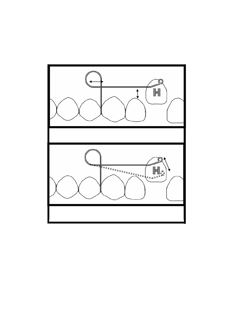
Figure
6 T- spring positioned on the second
premolar (occlusal view)
34
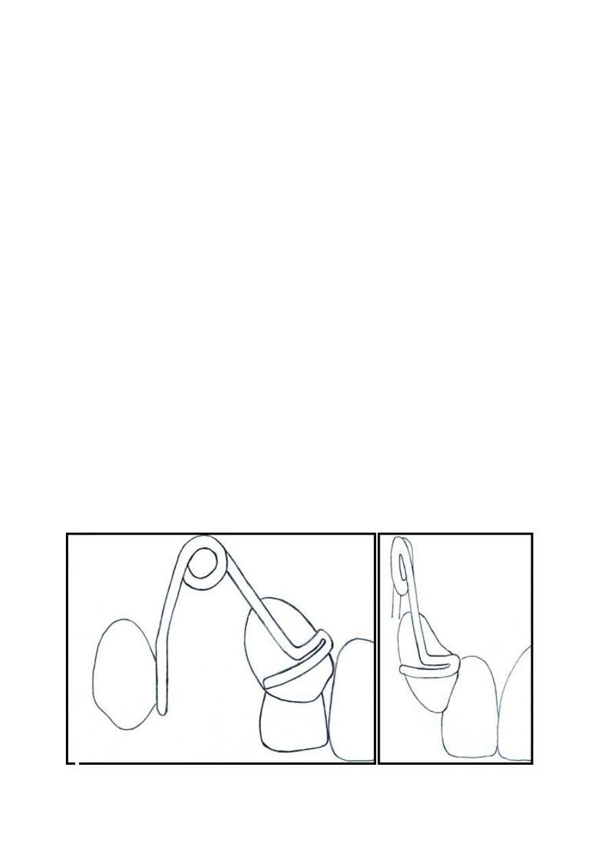
Lab:7. The Buccal Canine Retractor
.
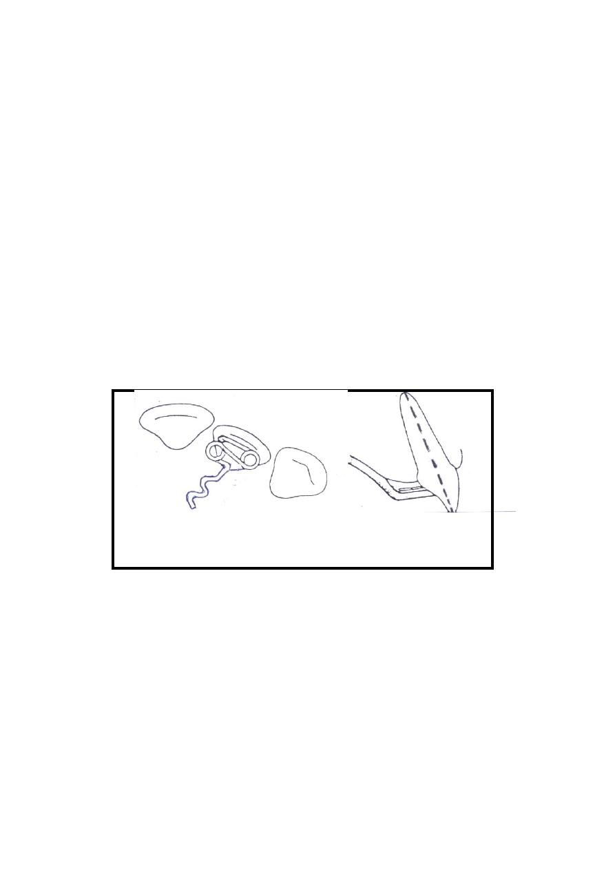
Description:
The buccal canine retractor is composed of a
posterior arm which emerges palatally from the acrylic
base plate and crosses the occlusal line up into the
vestibule to support a coil from which the (L) shaped
active arm (Singh 2007) is extended on the middle of the
crown (mesio-distally) and curved to engage the crown
mesially (figure:7), It is usually made of 0.7mm wire.
The coil must be 3-5 mm in diameter and situated
roughly on the line representing the centre of the
extracted first premolar space. Care must be taken for the
coil not to interfere with the vestibular tissues, for that
reason the coil must be in position no less than 2 mm
short from the sulcus depth. The end of the active arm is
preferred to have a small loop to prevent injury during
insertion.
Figure
7 The buccal canine retractor.

35
Indications:
It is typically indicated in situation where the canine
overlaps the lateral incisor labially.
Advantages:
1- Offers good control on the canine during distal
movement.
2- Prevent unwanted buccal movement.
4- It generally displaces the appliance less than palatal
spring does.
5- Well accepted by adults because it is unnecessary to
use clasping or labial bow on the anterior teeth.
Disadvantages:
1- Because of the heavy gauge of the wire, excessive
force can be easily exerted on the canine during
retraction.
2- It can cause trauma to the vestibular tissues.
Step by step construction procedure:
1- Sketch the design on the cast according to the
description.
2- Cut about 8cm of 0.7mm stainless steel wire and
straighten it.
3- Place the wire on the buccal surface of the canine
and horizontally at a mid-point of the crown
(occluso-gingivally) and construct a rounded curve
Please note that this section is for training purpose only and the
construction steps are not required in any written or verbal exam.

36
that extends mesially adapted to the tooth surface
ending at the farthest point that could be reached on
the mesial surface of the canine.
4- On the point at the buccal midline of the crown
(mesio-distally) mark a point where a (90) degrees
bend will be placed to redirect the wire apically.
This will form the (L) shape feature of the active
arm. The active arm will extend up to the vestibule
along the tooth long access.
5- With a permanent marker, put a mark on the wire at
the position about 2 mm shorter to the sulcus depth.
6- Hold the wire 2 mm shorter that the mark point and
start to make a loop of about 3-5 mm in diameter,
note that the active arm should always be under the
coil.
7- Complete the turn of the coil so that the remaining
wire is directed back downward.
8- Now put the wire in position and adjust the
remaining wire to point to the embrasure between
the first and the second premolar while the active
arm still fitted on the mesial border of the canine.
9- Mark the point at the interdental space near the
gingival margin on the remaining wire piece where a
light bend is made to direct the wire piece vertically
at the mesial occlusal margin of the second
premolar.
10-
Mark the wire at the occlusal level. Hold the
wire from the marked point and make a sharp bend
palatally.
11-
Now put the wire in position again and mark
the palatal occlusal margin of the premolar where
another bend is to be made to adapt the wire on the
palatal surface

37
12-
While the wire passes on the palate, a zigzag or
a hook form is made for retention. This retention
form is very important since the spring in its action
tends to rotate in the acrylic which might cause
loosening of the spring attachment and loss of.
13-
Cut the remaining wire and put the spring in
position then start to adapt the spring so that it will
be about 1mm away from the buccal and palatal soft
tissue.
14-
Now check for the fallowing points while the
spring in position:
a) The coil is 2mm away from the vestibule
b) The spring is 1mm away from the soft tissue.
c) If the first premolar already extracted, make sure
that the wire passes mesial to the second premolar
and with the occlusal level to avoid interference
with the retracted canine.
d) Check if there is interference with the opposite
arch in occlusion.
Activation:
Activation of the canine retractor is made by closing
the coil so that the active arm move about 3mm
posteriorly.
38
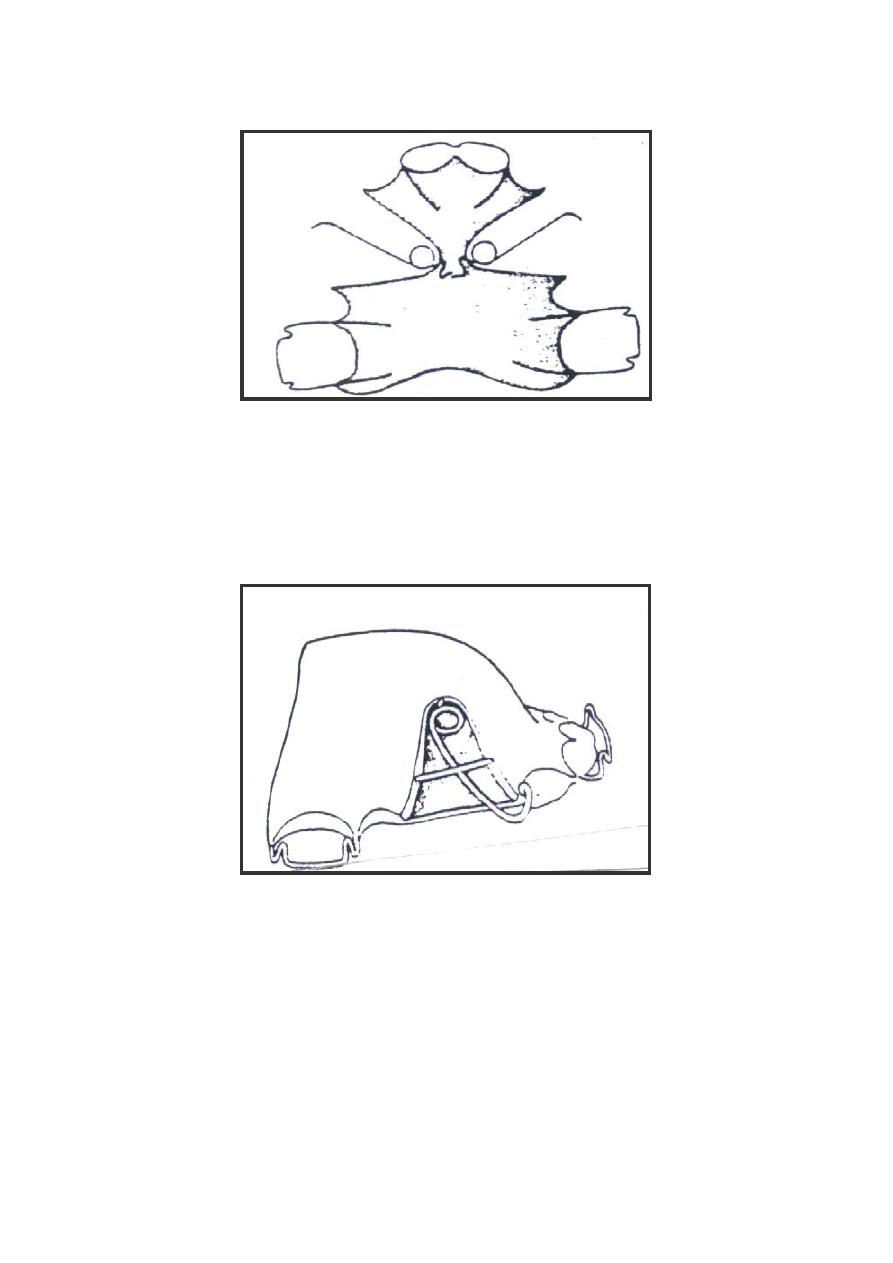
Lab:8. The Modified Buccal Canine
Retractor
Many modifications have been made on the buccal
canine retractor to enhance the control over the retracted
canine. One important modification to the canine
retractor is that made to the end of the active arm in order
to increase the control during retraction, facilitate light
extrusion force and to enable the palatal movement of the
canine at the end of the retraction using the same spring.
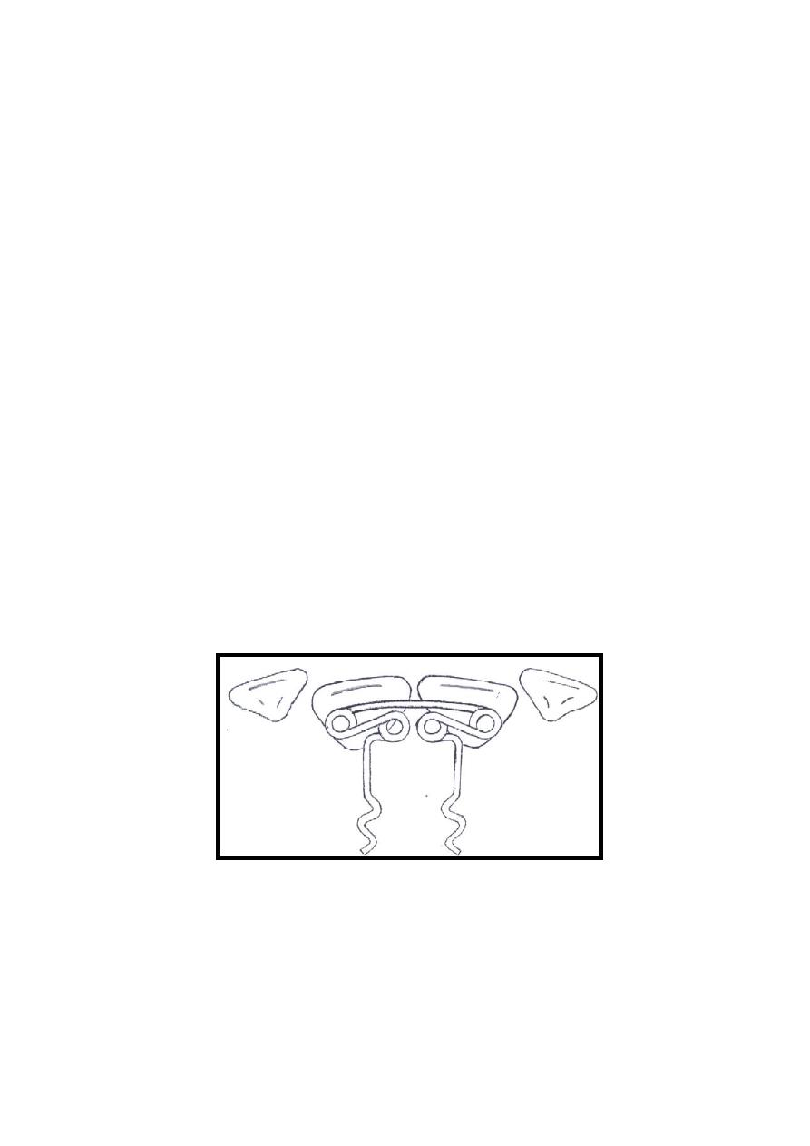
Description:
Generally, the spring has the same form and shape
of the buccal canine retractor also the active arm is
situated at the middle of the crown (mesio-distally). The
head (the end of the active arm) which is modified to
have an extension mesially and distally, which is adapted
on the labial surface of the canine and curved to partially
cover the mesial surface and extended to engage the
distal surface so as to make an excellent control over the
canine (figure 8:A and B).
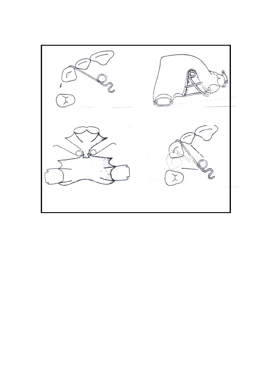
Figure
8 Modified Buccal Canine Retractor. A:Side view ; B: Anterior view

39
Indications:
1. Where the canine overlaps the lateral incisor labially.
2. Buccally erupted canine which is situated out of the
dental arch and need to be moved palatally
3. Partially erupted and high positioned canine.
Advantages:
1. Offers an excellent control on the canine during distal
movement.
2. Enables extrusion and palatal movement of the canine
at the end of the treatment with out the need for
modification that might cause corruption of the spring.
3. It generally displaces the appliance less than palatal
spring does.
4. Well accepted by adults because it is quite unnecessary
to use clasping and labial bow on the anterior teeth
Disadvantages:
1- Because of the heavy gauge of the wire, excessive
force can be easily exerted on the canine during
retraction.
2- It can cause trauma to the vestibular tissues.
Step by step construction procedure:
1- Sketch the design n the cast according to the
description.
2- Cut about 10cm of 0.7mm stainless steel wire and
straighten it
A
B
Please note that this section is for training purpose only and the
construction steps are not required in any written or verbal exam.

40
3- put the wire on the labial surface of the canine so that
the tip of the wire fit at the distal border of the canine
just under the distal contact point and put a mark about
2mm anterior to the mesial border of the canines.
4- Hold the wire at the mark point and form a loop which
leaves the remaining wire pointing distally. Now hold
the wire from the bottom of the U shape loop and bend
it to a right angle to make a small ledge that will adapt
to and catch the mesial surface of the canine when the
spring is in position. The horizontal part at the end of
the wire must also be adapted on the labial surface.
5- Put the wire in position and mark the point at the
centre of the crown where a sharp bend is to be made
upward to the vestibule parallel to the long axes of the
tooth.
5- With a permanent marker, put a mark on the wire at
the position about 2 mm shorter to the sulcus depth.
6- Hold the wire 2 mm shorter that the mark point and
start to make a loop of about 3-5 mm in diameter, note
that the active arm should always be under the coil.
7- Complete the turn of the coil so that the remaining
wire is directed back downward.
8- Now put the wire in position and adjust the remaining
wire to point to the embrasure between the first and
the second premolar while the active arm is still fitted
on the mesial border of the canine.
9- Mark the point at the interdental space near the
gingival margin on the remaining wire piece where a
light bend is made to direct the wire piece vertically at
the mesial occlusal margin of the second premolar.
10- Mark the wire at the occlusal surface. Hold the wire
from the marked point and make a sharp bend
palatally.

41
11- Re-position the wire and mark the palatal occlusal
margin of the premolar where another bend is to be
made to adapt the wire on the palatal surface
12- While the wire passes on the palate, a zigzag or a
hook form is made for retention. This retention form is
very important since the spring in its action tends to
rotate in the acrylic which might cause loosening of
the spring attachment and loss of action if it is not
properly made.
13- Cut the remaining wire and put the spring in position
then start to adapt the spring so that it will be about
1mm away from the buccal and palatal soft tissue.
14- Now check for the fallowing points while the spring
in position:
a- The coil is 2mm away from the vestibule.
b- The spring is 1mm away from the soft tissue.
c- If the first premolar already extracted, check if the
wire passes mesial to the second premolar with the
occlusal level to avoid interference with the retracted
canine
d- Check if there is interference with the opposite arch
in occlusion.
Activation:
Activation of the canine retractor is made by closing
the coil so that the active arm moved about 3mm
posteriorly.

42
Lab:9.
Adam's Clasp .
Also named as the arrowhead clasp. It was designed
By Adam's in 1970 and since then it is the most
commonly used clasp to provide retention for removable
appliances. The clasp is constructed in 0.7mm wire and
most commonly used on permanent first molars but can
be used for almost any tooth.
A partially erupted molar which has less than 4 mm of
crown generally gives poor retention. However, Adam's
clasp needs only 0.25mm of undercut to provide an
acceptable retention which is usually available at the
mesio-buccal and the disto-buccal undercuts. In case the
crown was not fully erupted, the clasp's arrowhead will
push the gingival margin aside and engage the undercuts
when inserted in patient's mouth; a gentle trimming of
the gingival line on the cast model is feasible. When the
molar is not available for retention, Adam's clasp can be
modified to involve two adjacent premolars or two
centrals; In this case 0.6mm wire is preferred.
Components:
1- The active parts
a. The arrow heads: Two small U shape loops act as
two fingers engaging the mesial and distal
undercuts.
b. The bridge: A horizontal piece of wire joining the
two arrow heads and about 2-3mm away form the
buccal tooth surface making roughly 45 degree
angle with the long axes of the crown.

43
c. The tags: The extension of the arrow heads on each
side which crosses the occlusal surface to the
lingual side.
2- The retentive part
Extends from the ends of the tags down to the
gingival margin and continue on both sides passing
about 10 mm along the palatal or lingual soft tissue
( must be 1mm away from the surface). This ends
by a small hook shape loops to increase retention of
the clasp.
Advantages:
1- A relatively shallow undercut is sufficient for
providing an acceptable retention.
2- The bridge of Adam's clasp provides an excellent grip
used for insertion and removal of the appliance.
3- Auxiliary springs, hooks and tubes for extra oral
extensions could be soldered to the bridge.
4-
The design has no sharp edges that may injure the soft
tissues
.
5- The original design can be modified to suit anterior
teeth.
Disadvantages:
1- The labially inclined anterior teeth make it difficult
for the arrow heads to engage the undercut at the
labial surface.
2- The point where hooks or tubes are soldered on the
bridge will be weakened and fracture is common at
that point.
3- Adam’s clasp needs pair of undercuts (at the
mesiobuccal and distobuccal embrasures of the tooth),
if one of them is occupied by a spring, it will be

44
difficult to incorporate two wires at the same
embrasure.
4- Crossing the occlusal surface at two places increases
the chance for occlusal interference.
Indications:
1- Most common for retention of removable
appliance.
2- Shallow undercuts.
3- Partially erupted molars.
4- Premolars and anterior teeth (after modification).
Step by step construction of Adam's clasp:
1- Sketch the design on the permanent molar. Starting
buccally by a descending vertical lines from the
tips of the mesiobuccal and distobuccal cusps down
to the gingival margin then join the two lines by a
transverse line at the junction between the gingival
and middle third of the crown. The drawing is now
is similar to the English letter ( H ) (figure: 9 )
2- If the tooth is partially erupted, carve a small piece
of the gingival margin about 1-2 mm at the mesial
and distal corners of the crown just behind the lines
sketched on the crown.
3- Now cut about 10cm of 0.7 mm wire and straighten
it.
4- Hold the wire by hands and adapt it on the
horizontal line of the (H) shape figure on the crown
and keep the tooth at the centre of the wire piece,
Please note that this section is for training purpose only and the
construction steps are not required in any written or verbal exam.

45
mark two points on the wire at the positions of the
vertical lines.
5- Start wire bending by making a 90 degree bend at
both points resulting into an angled U shape. The
small wire span between the two bends will be the
bridge.
6- Mark the wire at 2mm away from the first bend on
both side, hold the wire with the pliers from the
marked point and make a small U shape loop
(around 1mm internal diameter) at the tip of the
round beak of the pliers. This will result in a two
small U shape loops each of them heading away
from the other, those are the clasp’s arrowhead.
7- Using the pliers hold the U shape loop on each side
and twist it to be at 45 degree angle to the bridge in
the horizontal plane and adapt it on the under cuts
of the molar, make any necessary adjustments so
that the arrowheads fits onto the undercuts.
8- From each side, and roughly at the same level of the
bridge hold the wire with the pliers and make a
sharp bent 70-90 degrees toward the tooth contacts
(Sandhya 2008). This will push the bridge away
from the malar crown. Then another bent bend must
be made at about 2mm away from the first bend that
will direct the wire toward the occlusal surface.
NOTE that these two bends could be combined in
one bend based on tooth anatomy and position.
9- Now fit the wire in position and check the
extensions of the wire on the occlusal surface, make
the necessary adjustment to adapt the two wire
pieces at the embrasure interdentally.
10-
While the clasp is in position, mark the wire at
the lingual margins of the crown and make a sharp
46
bend down gingivally. Let the wire extend about
10mm on the gingival surface then a small hook
shape bend may be made for retention of the clasp
in the acrylic.
11-
Now fit the upper and lower arches together in
occlusion and check for occlusal interference, any
error must be corrected.
12-
For the finished Adam's clasp the following
points must be checked
a. The arrowheads engage the undercuts
b. The bridge is about 2 mm away from the tooth
surface
c. No occlusal interference with the opposite arch
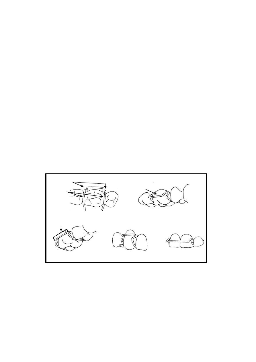
v
Tube soldered to
the bridge
Adam's
clasp
arrowh
eads
Ta
gs
The
bridge
Tu
be
Adam's clasp on
premolar
Adam's clasp on
centrals
Figure
9 Adam’s Clasp

47
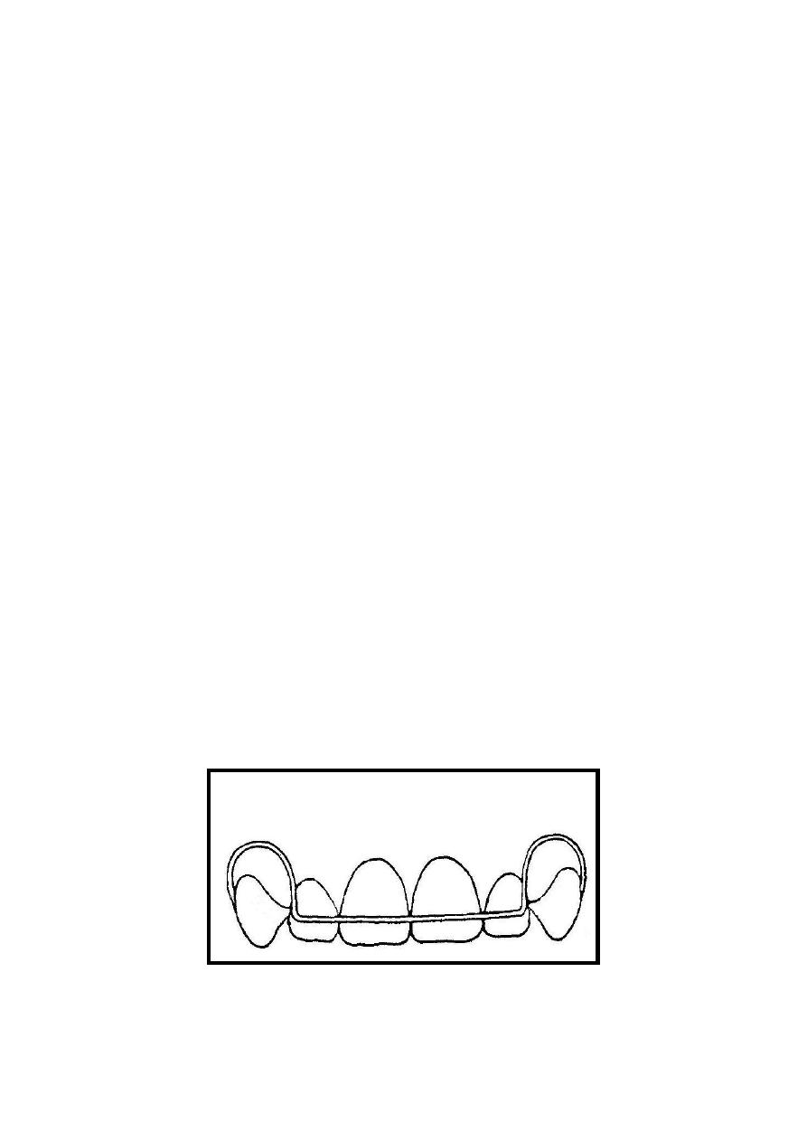
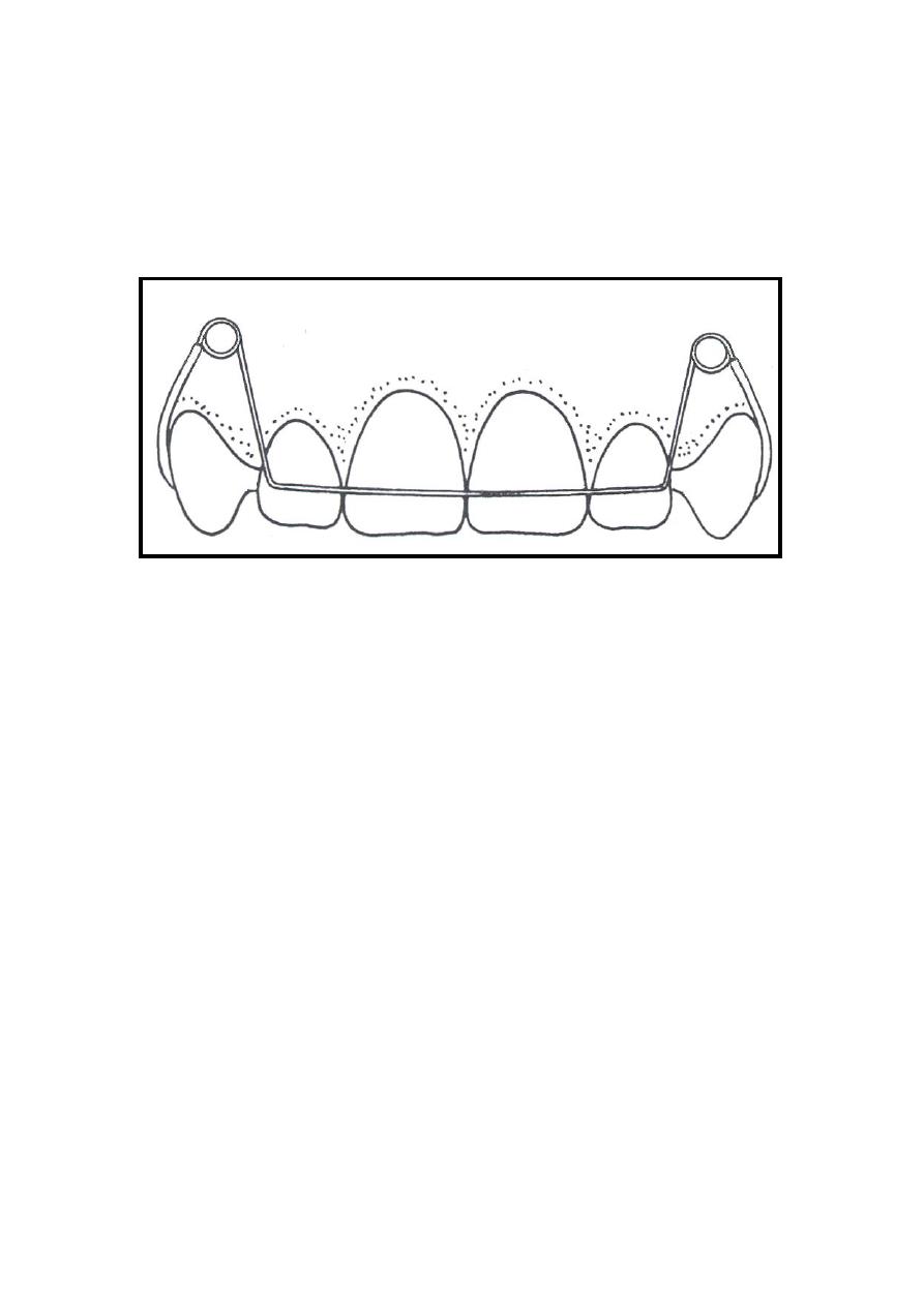
Lab:10.
The Labial Arch
.
Since it was first designed by Charles Hawley in the
1920s the labial arch has been widely used in
construction of removable appliances for both active and
passive purposes despite its relatively deficient aesthetic
appearance.
Description:
Howley labial arch is constructed with 0.7mm wire
gauge and that rigid wire give it the chance to share in
retentive and active treatment and resist distortion that
might be resulted from the relatively long and
complicated design
,
The basic design is composed of a horizontal wire
piece extended on the labial surface of the four incisors,
joined by vertical loops from both sides and extended to
about 3mm short than the labial vestibular depth, then
crossed the occlusal surface distal to the canine and
extended on the palatal soft tissue, ended by hooks for
retention.
Indications:
1- As an active component
a. Retraction of the anterior segment (four incisors)
and treatment of minor anterior irregularities.
b. Share with the Z and Double Z springs to produce
couple forces for correction of simple anterior teeth
rotations.

48
2. As passive component
a. Stabilization of the corrected malocclusions when
used as a retainer after active orthodontic treatment.
b. Provide anterior retention and stability of the
removable appliance.
c. Act as a splint for the anterior segment to increase
the anchorage of the removable appliance during
active treatment.
Advantages:
1. It is useful to produce force on single or group of teeth
and at the same time give retention of the appliance.
2. The same appliance used to correct malalignment of
teeth will continue to retain their corrected positions.
Disadvantages:
1. It has relatively poor aesthetic appearance as it appears
on the labial surface of the incisors makes it
unacceptable by some patients.
2. Skill is required for adaptation of the bow and in the
same time to prevent the wire from traumatizing the
soft tissues.
3. Care must be taken during activation of the labial arch
as a small activation might produce a very large force.
4. Subjected to distortion when it mistakenly used by
patient to insert and dislodge the appliance.

49
Step By Step construction:
1.
Sketch the design on the cast as shown in (figure:10).
2.
Take about 15 cm of 0.7mm wire. DO NOT straighten
it as the curve of the wire is useful to produce a
uniform anterior bow.
3.
Put the wire on the labial surface of the anterior
segment so that the centre of the wire piece fits against
the midline between the central incisors and
horizontally at the junction between the middle and
gingival third of the crown.
4.
Mark two points one on each side of the anterior
segment at the distal border of the lateral incisor.
5.
Using the pliers, hold the wire from one of the marked
points and make a sharp 90 degree angle bend, repeat
the procedure for both points so that the curved arch
form span between the two bends fits to the dental ach
while the wire pieces from both sides head toward the
vestibule.
6.
Now re adapt the wire in position and put a mark at
both sides bout 7mm shorter than the vestibule depth,
this will leave roughly 3mm of vestibular clearance
after forming the loops. Grab the wire from the
marked point and start to form a U shape loop directed
away from the bow, the diameter of the U shape loops
must be no less than 5mm.
7.
Put the wire in position. Make any necessary
adjustments to maintain the U shape loops in the
buccal vestibule vertically and horizontally so as to
have 1-2mm clearance from the soft tissue.
Please note that this section is for training purpose only and the
construction steps are not required in any written or verbal exam.
50
8.
After that, mark the wire at the embrasure between the
canine and the first premolar and bend the wire from
that point palatally.
9.
Palatally, the wire pass about 10mm ending with a
small hook to provide retention in the acrylic, make
sure that the wire must be 1-2mm away from the soft
tissue.
Activation:
The flexibility of the labial arch is highly dependent
on the length of the U shape loops, while it is relatively
resilient in the vertical direction; it is very hard in the
horizontal direction, only 1mm activation is quite enough
to produce movement of the four incisors.
Activation of the labial arch during retraction of
anterior teeth is done from the U shape loops by closing
the loops so that the arch will move 1mm palatally, the
activation must not exceed that because it will produce
excessive force on the centrals. Care must be taken not to
distort the bow or traumatize the soft vestibular tissue
Figure
10 Labial Arch , Anterior view

51
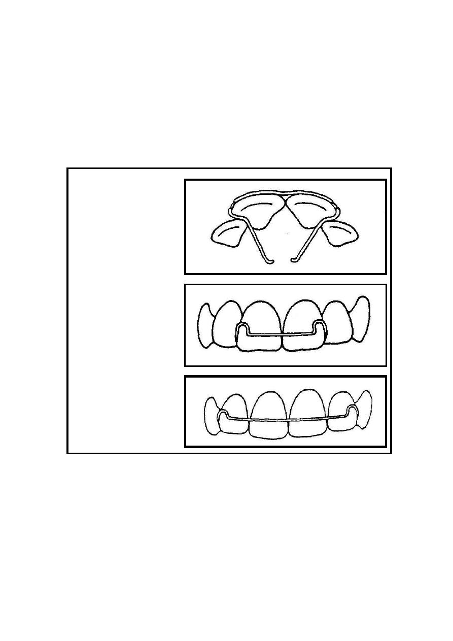
Lab:11.
The Fitted Labial arch
.
When the anterior teeth are proclined so that neither
the Adam's clasp nor the labial arch was suitable, anterior
retention is provided by a modification that combines
both. This was named fitted labial arch.
The basic design is composed of a horizontal wire
span fitted on labial surface at the junction between the
incisal and middle third of the incisors and extended over
two or four incisors ending from both sides by a small 2-
3mm U shape loops directed gingivally. The wire then
passes from both sides to cross the occlusal surface to the
lingual side ending by a hook-like bends for retention in
the acrylic.
Indications:
1. Proclined anterior teeth.
2. Anterior retention is required where labial arch is
not suitable. An example for that is the use of
unilateral canine retractor.
Advantages:
1. Simple in construction and adaptation.
2. Provide good retention of the appliance anteriorly
Disadvantages:
1. Poor aesthetic as it approaches the incisal margin.
2. May interfere with the opposite arch during
occlusion.

52
Step by step construction:
1. Sketch the design on the cast according to the
description above.
2. Make the necessary wire bending to adapt the wire
horizontally on the labial surface so that it will
fallow the curvature of the incisors and mark it
about 4mm short to the distal end of the incisors
from both sides.
3. Now hold the wire from the marked point and make
a sharp 90 degree angle bend, repeat the bend for
the other side.
4. Hold the wire with the pliers beaks near the first
bend and start forming a U shape loop and repeat
the procedure for the other side. The diameter of the
loops should be about 2-3mm so that the resulted
wire will fit to the dimensions of the involved teeth.
5. Re position the wire and make any necessary
adjustment so that the wire fits against the labial
surface of the incisors, place marks on the wire from
both sides at the incisal margin where a sharp bend
will turn the wire direction down to the palatal or
lingual surface.
6.
The wire from both sides must be extended about
one cm on the palatal soft tissue ending by retentive
hooks
.
Activation or tightening of the wire:
Please note that this section is for training purpose only and the
construction steps are not required in any written or verbal exam.
53
The fitted labial arch provide retention through the
horizontal bow which is fitted exactly on the labial
surface of the incisors, tightening of the bow is made
through the adjustment of the U shape loops that
makes the bow tighter on the labial surface.
A:
Occlusal view of the fitted
labial wire, note the closely
fitted addaptation of the
wire on the labial surface of
the incisos.
B:
Short Fitted labial wire
involves the two central
incisors only.
C 3:
Long fitted wire involves
the four incisors
Figure
11 Fitted labial arch

54
Lab: 12. Robert's retractor .
.
This is a flexible bow constructed with 0.5 mm
stainless steel wire. It is composed of a bow which
extended on the labial surface of the four incisors. The
bow takes the shape of an ideal arch form despite the
irregularities of the anterior teeth as they will be gathered
when retracted. At both ends a sharp bend will direct the
wire gingivally where it will form a 3-5 mm coil not less
than 3mm shorter than the full depth of the vestibule.
The coil Then changes the redirected of the wire
occlusally where it will cross the occlusal surface distal
to the canine and turn onto the palatal surface.
Robert's retractor is highly flexible in all its parts
except at the part from the coil to the acrylic base plate
where it will be shielded by a 0.5mm stainless steel tube
to support the structure of the flexible bow.
In this lab and only for training purpose the full
design will be constructed with 0.7mm wire which is
believed to be much easier in construction and
adaptation.
Indications:
1. Retraction of anterior segment
2. correction of spacing or minor irregularities
Advantages:
1. This spring produces a light force and easily
adjustable.

55
2. Because it swings backward and downward it will
not slide gingivally on the anterior teeth when
retracted.
Disadvantages:
1. If the supporting arms are not correctly positioned
the sulcus may be traumatized
2. In case of breakage major re construction will be
required.
Step by Step construction:
1. Sketch the design on the cast model as shown in
(figure 12).
2.
Take about 15 cm of 0.5mm (0.7mm for training
only). Don’t straighten it as the curve of the wire is
useful to produce a uniform anterior bow.
3.
Place the wire on the labial surface of the anterior
segment so that the centre of the wire piece fit
against the midline between the central incisors and
vertically at the junction between the middle and
gingival third of the crown.
4.
Adjust the wire by your hands to make an anterior
bow that simulate the normal arch form of the
patient. Despite the irregularities of the anterior
teeth, the bow must be a uniform arch.
5.
Mark two points one on each side of the anterior
segment at the distal border of the lateral incisor.
Please note that this section is for training purpose only and the
construction steps are not required in any written or verbal exam.

56
6. Hold the wire with the pliers from one of the
marked points and make a sharp 90 degree angle
bend, repeat the procedure for both points so that
the bow extends horizontally on the labial surface of
the incisors while the wire pieces from both sides
head toward the vestibule.
7. Now re adapt the wire in position and place a mark
at both sides bout 7mm shorter than the vestibule
depth, grab the wire from the marked point and start
to form a 3-5mm coil, note that the active arm (near
to the bow) must be under the coil.
8. Re-position the wire and make any necessary
adjustment to maintain the coils in the curvature of
the dental arch vertically and horizontally.
9. Inset the wire from both sides into a stainless steel
tube which will extend from the coil to the acrylic
Base plate in the finished appliance (this step will
not be done with 0.7 wire only for training).
10.
After that, mark the wire (the tube) at the
embrasure between the canine and the first premolar
and bend it from that point Palatally.
11.
On the palate, the wire pass about 10mm ended
with a small hook to provide retention in the acrylic,
make sure that the wire in must be 1-2mm away
from the soft tissue.
Activation:
This
bow is light and flexible. An adjustment of
about 3mm is suitable but the site of adjustment is very
important because if the wire is activated at the point
where it emerges from the supporting tube (a sight of
stress concentration) it will often fracture. The bow is
57
adjusted by bending in the vertical limb below the coil.
As the incisors retracted the bow swings downward and
backwards and the level of the horizontal part will need
adjustment.
Figure
12 Robert Retractor, Front view

58
Lab: 13 .
Acrylic base plate .
The acrylic base plate constitutes the body of the
removable appliance. It has thee functions:
1. Act as the foundation into which the retaining clasps
and active components of the appliance are
embedded, such as springs and screws.
2. Contribute to the anchorage during the course of
active tooth movement. This might be achieved
though the close fit of the acrylic to the palatal
surface of the teeth and palate.
3.
It could be extended to form bite planes to
disengage the occlusion or produce overbite
reduction
.
Design:
The design of the acrylic base plate depend on the
case to be treated, each case may have deferent
modifications according to the components to be
incorporated into the design. But there are general points
that must be considered during the construction of the
acrylic base plate:
1. Several types of acrylic materials could be used for
construction of the base plate, but chemical cured
acrylic resin is commonly used since it is economic
and less labor intensive.
2. The base plate needs to be thick enough to carry the
retentive and the active components, but should be as
thin as possible to avoid discomfort to the patient,
ideally, this should be as thick as a sheet of modeling
wax (2-3)mm.

59
3. The base plate should normally cover most of the hard
palate, finishing just distal to the first molars.
4. It should fit closely to the palate and around the teeth
that are not to be moved, extends up to one third of the
crown length. Whereas the teeth being moved should
have enough clearance around to move freely.
5. The clasps or springs retentive parts should be
embedded in the acrylic, exposure of the wire may
cause future dislodgement or malfunction of the
springs and clasps.
Modifications to the Acrylic base plate:
The design of the base plate may be modified to
accommodate springs as in boxing , add an active
extensions as in Bite planes , or to accommodate
expansion screws to the basic design.
1- bite planes
The acrylic may be thickened palatal to upper
incisors to form the anterior bite plane or may be
extended on the occlusal surface of the posterior teeth
to form a posterior bite plane.
a- Anterior bite plane
The principal use of the anterior bite plane is for the
reduction of the overbite. This occurs primarily by
alteration of the rate of eruption of the posterior teeth
relative to the lower anterior. Several points must be
considered during the construction of the anterior bite
plane:

60
1. Vertically, the acrylic should be as high as that
when the lower anterior teeth are in contact with the
acrylic bite plane the premolars are separated by 2-
3mm.
2. The posterior limit of the anterior bite plane should
extend just sufficiently to engage the lower incisors.
3. The anterior bite plane should be made with the
occlusal surface parallel to the occlusal plane.
Inclined
bite
planes
may
cause
unwanted
movements. However this may be required in some
cases.
4. Adjustment of the bite plane may be done by
addition of acrylic which may be lost due to
occlusal wear between visits.
5. If the lower incisors are irregular, adjustment of the
bite plane surface is needed to provide contact with
at least 3 lower incisors, then few visits later
leveling of the occlusal plane is possible to lower
anterior level.
b- Posterior bite plane
It is occasionally necessary to extend the base plate to
cover the occlusal surfaces of the posterior teeth
bilaterally to open the bite and so relief the incisal or
cuspal lock while an anterior cross bite or a bucco-
lingual abnormality is being corrected.
Few points must be considered during the
construction of posterior bite plane:
1.
The posterior bite plane should be thick
enough just to disengage the interlocking of the
anterior teeth and permit correction of cross bite.

61
2.
The posterior bite plane should extend on the
first molar and premolars and should be faceted to
accommodate the cusps of the opposing teeth.
3.
It must be simultaneously in contact in both
sides, any correction must be made using articulating
paper.
4.
The mandible must be at a centric relation, this
is achieved by putting a piece of modeling wax on the
occlusal surface of the molars and premolars and
instruct the patient to close in centric relation to the
desired height. Then transfer the wax records with the
upper and lower cast to the articulator.
5.
It is important that the (tags) which is the parts
of the clasp that crosses the occlusal surface must be
free from acrylic of the bite plane, presence of acrylic
surrounding the wire may cause limitation of the
flexibility of the wire. This achieved by covering the
wires with wax before applying acrylic.

62
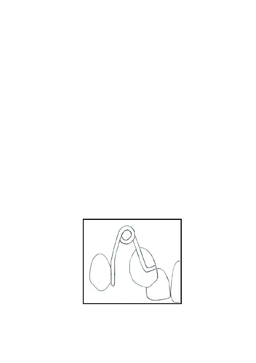
2 Boxing, Open spring and Wire guard:
Those are three designs of the acrylic base plate
around the palatal springs. Boxing (Figure 14) is to
make the active arm and the coil free to move inside
an acrylic chamber built into the base-plate, while
open spring (Figure 13) is to completely remove the
acrylic of the base-plate from the path of the
movement and leave the active arm and the coil free
without protection, the guard wire (figure 14) may
be incorporate in the open spring design to prevent
distortion of the spring during wearing and activation,
it could be added from the tongue side or occasionally
from both sides, it may also be used with the boxing
design palatally for the same reason.
Boxing is made by covering the entire spring with
wax except at the retentive part. The wax must also
cover the area at which future activations may occur
so that the spring will move freely along its range of
action. The acrylic base plate material should then
cover the palatal surface including the boxed spring
with the same thickness which will form a bulge or
elevation at the area of boxing. Then after the acrylic
is set, a hot water bath will eliminate the wax leaving
the spring to move in an acrylic chamber attached
only at its retentive part with the acrylic.
Open spring and guard wire are made in the same
manner except that the acrylic will not cover the
boxed area but leave it opened with out acrylic or
crossed by a piece of wire to protect the spring in
case of guard wire (Figure:13) .
63
Figure
13 Open spring
Figure
14 Combined Boxing and Wire guard
64
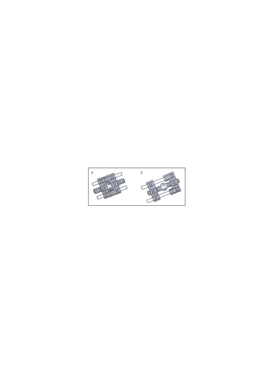
Lab:14.
Orthodontic Screws
3 Orthodontic Screws
An alternative method of providing orthodontic
force is to use expansion screw as an integral part of
the removable appliance (Figure 15). The screw
normally transmits its force by means of acrylic,
which comes in contact with the teeth. Many types of
screw are commercially available for use in removable
appliance (one dimension, two dimensions , fan shape,
etc…), the type of the screw is specific for each case
and have to meat the requirements of an Adequate
travel, Stability and minimal bulk.
Description:
Screws are produce by a number of manufacturers and
a wide range of sizes and shapes are available.
Typically, the design has a central threaded screw,
each end of which engages into a small metal or
plastic block. One of this blocks caries two guide
wires which lie parallel to the screw and pass through
holes in the opposing block. The centre of the screw is
enlarged into a small boss into which four radially
positioned holes are visible. A small wire key is
supplied and activation is made by insertion of the key
Figure
15 Orthodontic Screws. A: 2sides; B: One Side.
65
into one of these holes and turned like a capstan
through 90 degree until it touches the guide. For
further activations the procedure must be repeated
with the key inserted into the next hole.
Uses:
Screws are recommended only in those few
situations where spring will be unsatisfactory.
Nevertheless, there are certain situations in which
screws are very useful, for example
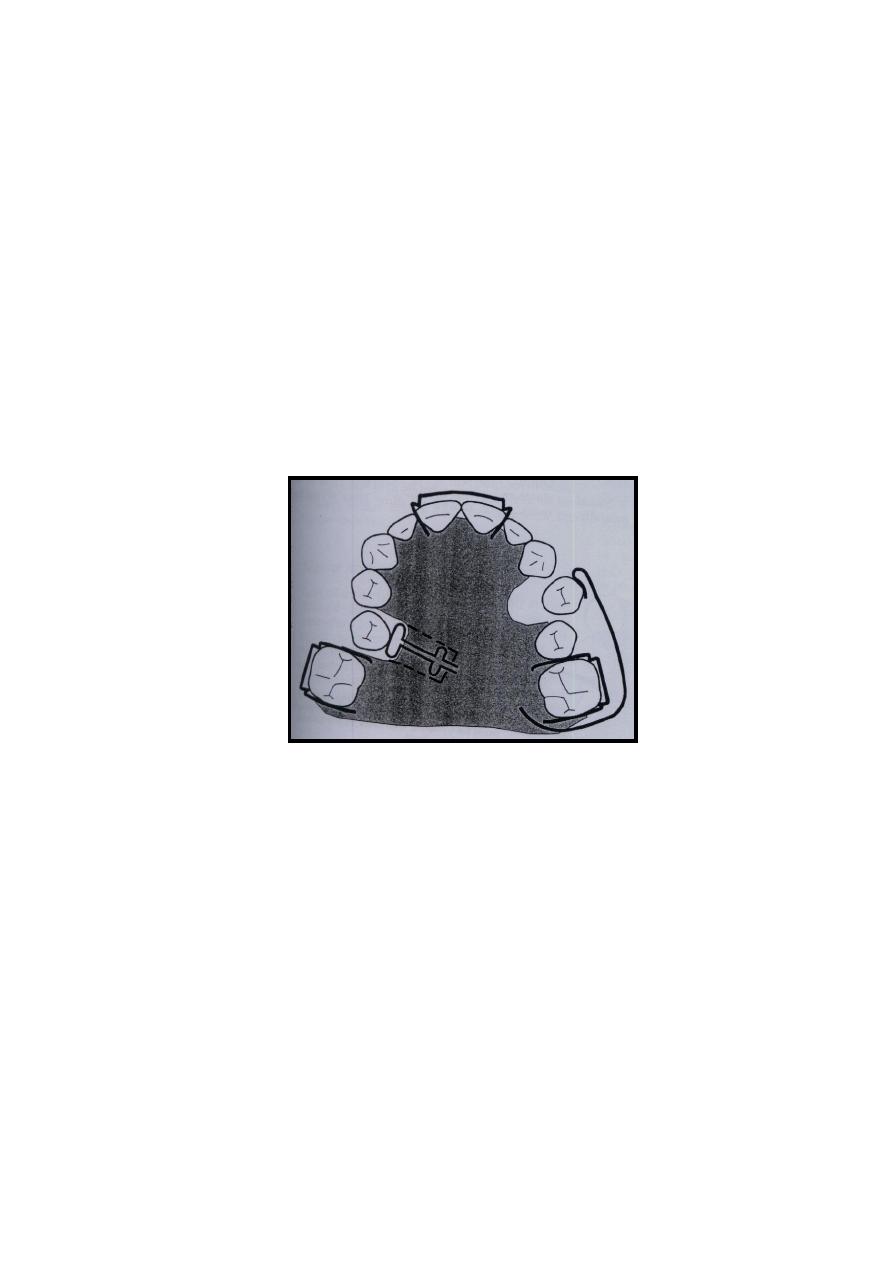
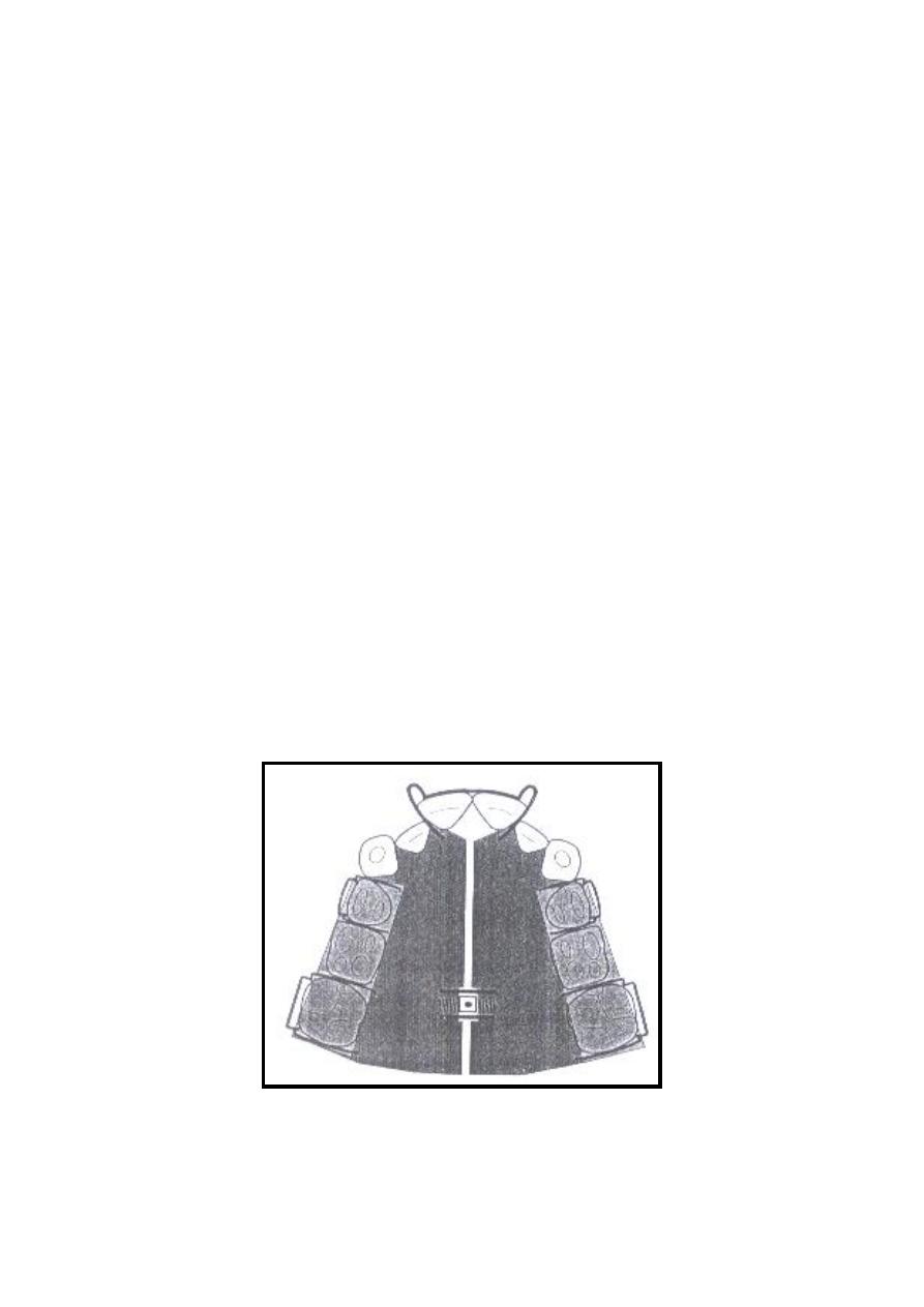
1. Expansion
It is some times necessary to increase the width
of the upper dental arch or to correct a unilateral cross
bite .Symmetrical widening of the upper arch could be
achieved by removable appliance with suitable design
containing four Adam's clasps on permanent molars
and premolars. In this case the screw should be placed
horizontally on the midline of the palate. In addition
to a shallow posterior bite planes to prevent secondary
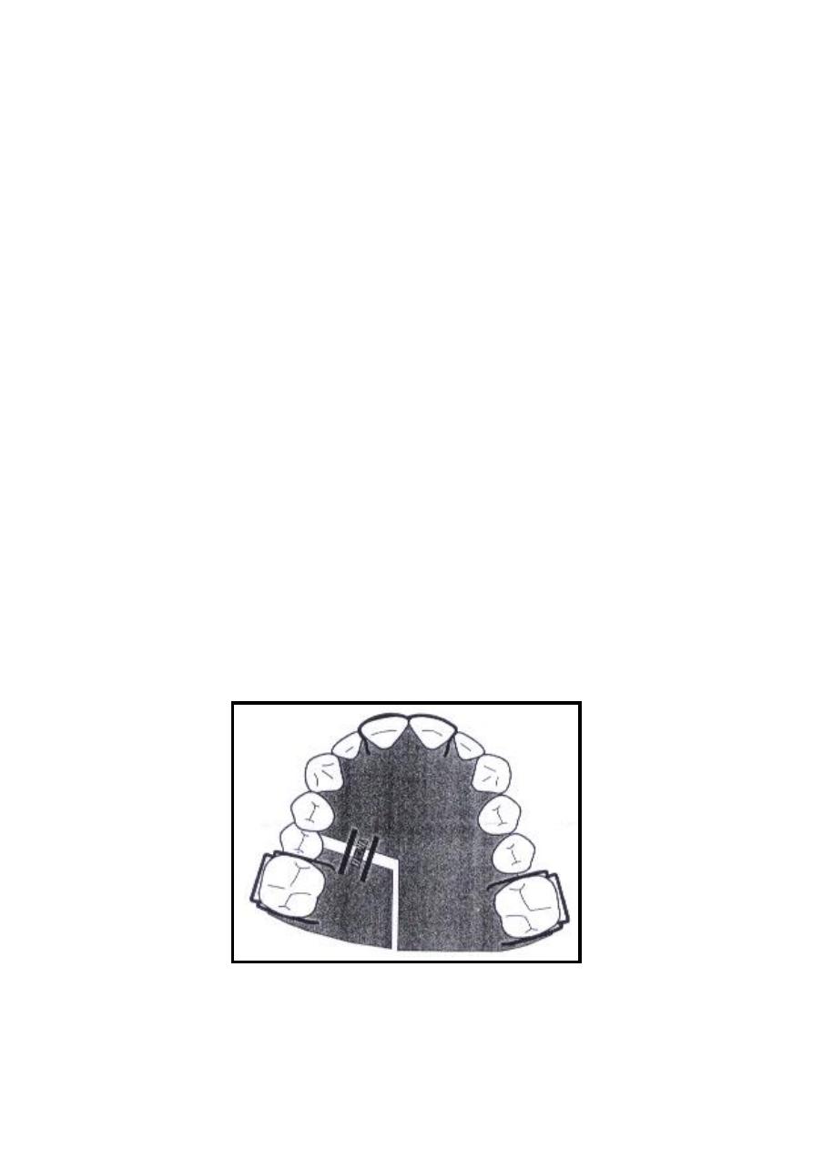
lower arch widening (Figure 16).
Figure
16 Orthodontic Screw at the midline used for expansion
66
2. Distal movement:
Distal movement of molars could be achieved by a
removable appliance carrying bilateral screws which
will deliver distally directed force to the molars.
Careful positioning of the screws will be necessary in
accordance with the three dimensional orientations of
the arch. A version with a screw only one side of the
appliance is also useful in a situation for example if
unilateral distalization of molar (Figure 17).
Positioning:
Although clasps and springs accept minor
adjustment to correct faulty positioning, screws can
only be corrected by cutting out the screw from the
acrylic and re-fabricate it. It is therefore very
important to accurately position the screw in the
three dimensions during construction.
Figure
17 Orthodontic Screw at one side of the arch used
for distal movement.

67
Disadvantages
1. Most important is the bulky appliance that will
cause discomfort to the patient.
2. over activation may cause difficulties in appliance
incretion and will gradually lose its fitness
3. Full cooperation of the patient is required since
relapse is quick and may elongate treatment time.
Adjustments:
Activation of the screw is done by inserting the key
wire into one of the activation holes and turn the screw
to the direction that will open the screw until the key
touches the guide bars ( the direction is usually
marked by an arrow on the screw), this will make
quarter turn. Farther activation means to repeat the
previous work. Activations are done by the patient
once or twice a week, each quarter turn will provide a
0.25mm opining that means about 1.5-2mm per month
which is considered a reasonable amount of tooth
movement.

68
References:
Sandhya, S.L., 2008. Orthodontic Removable Appliance
2nd ed., Jaypee.
Singh, G., 2007. Textbook of Orthodontics 2nd ed.,
Jaypee.