Breathing Circuits In Anaesthesia
Key conceptsBecause insufflation avoids any direct patient contact, there is no rebreathing of exhaled gases. Ventilation cannot be controlled and the inspired gas contains unpredictable amounts of entrained atmospheric air.
Long breathing tubes with high compliance increase the difference between the volume of gas delivered to a circuit by a reservoir bag or ventilator and the volume actually delivered to the patient.
The adjustable pressure limiting (APL) valve should be fully open during spontaneous ventilation so that circuit pressure remains negligible throughout inspiration and expiration.
Because a fresh gas flow equal to minute ventilation is sufficient to prevent rebreathing, the Mapleson A design is the most efficient Mapleson circuit for spontaneous ventilation.
The Mapleson D circuit is efficient during controlled ventilation, because fresh gas flow forces alveolar air away from the patient and toward the APL valve.
The drier the soda lime, the more likely it will absorb and degrade volatile anesthetic.
Malfunction of either unidirectional valve in a circle system may allow rebreathing of carbon dioxide, resulting in hypercapnia.
With an absorber, the circle system prevents rebreathing of carbon dioxide at fresh gas flows that are considered low (FGF ≤ 1 L) or even FGF equal to the uptake of anesthetic gases and oxygen by the patient and the circuit itself (closed system anesthesia).
Because of the unidirectional valve, apparatus dead space in a circle system is limited to the area distal to the point of inspiratory and expiratory gas mixing at the Y-piece. Unlike Mapleson circuits, the circle system tube length does not directly affect dead space.
The fraction of inspired oxygen (FIO2) delivered by a resuscitator breathing system to the patient is directly proportional to the oxygen concentration and flow rate of the gas mixture supplied to the resuscitator (usually 100% oxygen) and inversely proportional to the minute ventilation delivered to the patient.
DEFINITION
A breathing system is defined as an assembly of components which connects the patient’s airway to the anaesthetic machine creating an artificial atmosphere, from and into which the patient breathes.It primarily consists of
a) A fresh gas entry port/delivery tube through which the gases are delivered from the machine to the systems;
b) A port to connect it to the patient’s airway;
c) A reservoir for gas, in the form of a bag or a corrugated tube to meet the peak inspiratory flow requirements;
d) An expiratory port/valve through which the expired gas is vented to the atmosphere;
e) A carbon dioxide absorber if total rebreathing is to be allowed and
f) Corrugated tubes for connecting these components.
Flow directing valves may or may not be used.
REQUIREMENTS OF A BREATHING SYSTEM
Essential:
The breathing system must
a) deliver the gases from the machine to the alveoli in the same concentration as set and in the shortest possible time;
b) effectively eliminate carbon-dioxide;
c) have minimal apparatus dead space; and
d) have low resistance.
Desirable:
The desirable requirements are
a) economy of fresh gas
b) conservation of heat
c) adequate humidification of inspired gas
d) Light weight
e) convenience during use
f) efficiency during spontaneous as well as controlled ventilation
g) adaptability for adults, children and mechanical ventilators
h) provision to reduce theatre pollution.
Many Configurations
Schimmelbusch mask
Mapleson systems
Circle system
Components of a breathing system
Adjustable pressure-limiting valveReservoir bag
Tubing
Adjustable pressure-limiting valve
Spill valve, pop-off valve, expiratory valve, relief valve.Designed to vent gas during positive pressure.
Pressure of less than 0.1 kPa activates the valve when open.
Components
3 ports:
inlet, patient and exhaust port- latter can be open to atmosphere or connected to the scavenging system
Lightweight disc sits on a knife-edge seating- held in place by a spring
Tension in the spring and therefore the valve’s opening pressure is controlled by the valve dial.
The Heidbrink valve
Single use APL valve( Intersurgical)
Operation of an Intersurgical single use APL valve
Mechanism of action
One-way, adjustable, spring-loaded valve
Valve allows gases to escape when the pressure in the breathing system exceeds the valve’s opening pressure
During spontaneous ventilation, the patient generates a positive pressure during expiration, causing the valve to open
During positive pressure ventilation, a controlled leak is produced in inspiration by adjusting the valve dial, allowing control of the patient’s airway pressure
Reservoir bag
Antistatic rubber or plasticEllipsoid in shape
Standard adult size is 2 l (range from 0.5 to 6 l)
Mechanism of action
Accommodates fresh gas flow during expiration acting as a reservoir available for the following inspiration.Acts as a monitor of patient’s ventilatory pattern during spontaneous breathing and also a very inaccurate guide to tidal volume
Used to assist or control ventilation
Tubing
Corrugated or smoothDifferent lengths depending on system being used
Allow humidification of inspired air
Parallel and coaxial arrangements available
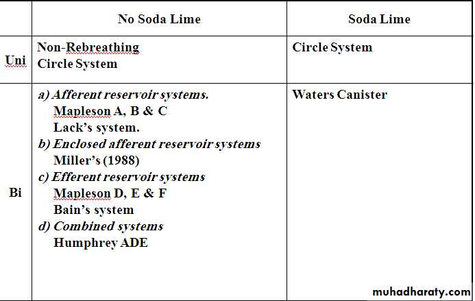
Mapleson classification
Mapleson classified breathing systems in 1954 into 5 types.Mapleson classification
Bi-directional flow
a) Afferent reservoir systems.
Mapleson A
Mapleson B
Mapleson C
Lack’s system.
B) Efferent reservoir systems
Mapleson D
Mapleson E
Mapleson F
Is that part of the breathing system which delivers the fresh gas from the machine to the patient. If the reservoir is placed in this limb as in Mapleson A, B, C and Lack’s systems, they are called afferent reservoir systems (ARS).
Efferent limb
Is that part of the breathing system which carries expired gas from the patient and vents it to the atmosphere through the expiratory valve/port.
If the reservoir is placed in this limb as in Mapleson D, E, F and Bain systems, they are called efferent reservoir systems (ERS).
Bi-Directional Flow
Systems with bi-directional flow are extensively used.
These systems depend on the FGF for effective elimination of CO2.
Understanding these systems is most important as their functioning can be manipulated by changing parameters like Fresh gas flow, alveolar ventilation, apparatus dead space, etc.
Fresh Gas Supply
Fresh gas flow (FGF) forms one of the essential requirements of a breathing system.
If there is no FGF into the system, the patient will get suffocated.
If the FGF is low, most systems do not eliminate carbon-dioxide effectively, and if there is an excess flow there is wastage of gas. So, it becomes imperative to specify optimum FGF for a breathing system for efficient functioning.
If the system has to deliver a set concentration in the shortest possible time to the alveoli, the FGF should be delivered as near the patient’s airway as possible.
Elimination Of Carbon-Dioxide
Normal production of carbon-dioxide in a 70 kg adult is 200 ml per minute and it is eliminated through the lungs.
Normal end-tidal concentration of carbon-dioxide is 5%. Hence, for eliminating 200 ml of carbon-dioxide as a 5% gas mixture, the alveolar ventilation has to be:
200 x 100 = 4,000 ml.
5
This 4000 ml is the normal alveolar ventilation. Any breathing system connected to an adult’s airway should provide a minimum of 4 litres per minute of carbon-dioxide free gas to the alveoli for eliminating carbon-dioxide. If the alveolar ventilation becomes less than 4 litres per minute, it would lead to hypercarbia.
Apparatus Dead Space
It is the volume of the breathing system from the patient-end to the point up to which, to and fro movement of expired gas takes place.
Extent of dead space in various systems
In an afferent reservoir system with adequate FGF, the apparatus dead space extends up to the expiratory valve positioned near the patient.
If the FG enters the system near the patient-end as in an efferent reservoir system, the dead space extends up to the point of FG entry.
In systems where inspiratory and expiratory limbs are separate, it extends upto the point of bifurcation.
Importance of FGF
The dynamic dead space will depend on the FGF and the alveolar ventilation.The dead space is minimal with optimal FGF.
If the FGF is reduced below the optimal level, the dead space increases .
The whole system will act as dead space if there is no FGF.
Increasing the FGF above the optimum level will only lead to wastage of FG.
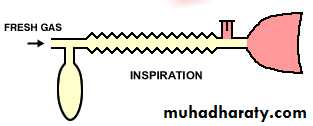
Mapleson A
Corrugated rubber or plastic tubing:
110- 130 cm in length
Reservoir bag at machine end
APL valve at the patient end.
Tube Volume > Tidal Volume (550mls)
Mapleson ‘A’/Magill’s system:Functional analysis:
Spontaneous breathing:The system is filled with fresh gas before connecting to the patient. When the patient inspires, the fresh gas from the machine and the reservoir bag flows to the patient, and as a result the reservoir bag collapses.
The expired gas, initial part of which is the dead space gas, pushes the FG from the corrugated tube into the reservoir bag and collects inside the corrugated tube .
Expiratory pause –
Fresh gas washes the expired gas out of the reservoir tube, filling it with fresh gas for the next inspiration.Rebreathing of alveolar gas can be prevented if the fresh gas flow = patient's minute ventilation.
Controlled ventilation:
To facilitate IPPV the expiratory valve has to be partly closed.
During inspiration, the patient gets ventilated with FG and part of the FG is vented through the valve after sufficient pressure has developed to open the valve.
During expiration, the FG from the machine flows into the reservoir bag and all the expired gas (i.e., dead space gas and alveolar gas) flows back into the corrugated tube till the system is full .
During the next inspiration the alveolar gas is pushed back into the alveoli followed by the FG. When sufficient pressure is developed, part of the expired gas and part of the FG escape through the valve .
This leads to considerable rebreathing, as well as excessive waste of fresh gas. Hence these systems are inefficient for controlled ventilation.
A fresh gas flow of >20 L/minute is required to prevent rebreathing during controlled ventilation.
Mapleson A (Magill circuit)
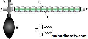
Mapleson A- Lack system
Coaxial modification of Magill Mapleson A1.5 m length
FGF through outside tube (30mm), exhaled gases through inner tube.
Inner tube wide in diameter (14 mm) to reduce resistance to expiration(1.6 cms H2O).
Reservoir bag at machine end
APL valve at machine end.
Better for spontaneous ventilation.
Lack’s system
This system functions like a Mapleson A system both during spontaneous and controlled ventilation.The only difference is that the expired gas instead of getting vented through the valve near the patient, is carried by an efferent tube placed coaxially and vented through the valve placed near the machine end . This facilitates easy scavenging of expired gas.
Lack’s system
Mapleson B system
The fresh gas inlet near the patient, distal to the expiratory valve.The expiratory valve opens when pressure in the circuit increases, and a mixture of alveolar gas and fresh gas is discharged.
During the next inspiration a mixture of retained fresh gas and alveolar gas is inhaled.
Rebreathing is avoided with fresh gas flow rates of greater than twice the minute ventilation for both spontaneous and controlled ventilation.
Mapleson C system
This circuit is also known as the Water's circuit.It is similar in construction to the Mapleson B, but the main tubing is shorter.
A fresh gas flow equal to twice the minute ventilation is required to prevent rebreathing. Carbon dioxide builds up slowly with this circuit.
Mapleson B & C systems
In order to reduce the rebreathing of alveolar gas and to improve the utilization of FG during controlled ventilation, the FG entry was shifted near the patient.This allows a complete mixing of FG and expired gas.
The end result is that these systems are neither efficient during spontaneous nor during controlled ventilation.
Ayre’s T - piece
Introduced by Phillips Ayre in 1937.
Belongs to Mapleson E .
Available as metallic / plastic .
Length- 2 inches.
Parts – inlet, outlet, side tube.
Inlet size – 10 mm.
Outlet size – 10 mm metalic 15 mm plastic.
Advantages:
Simple to useLightweight
No dead space, no resistance.
For pediatric pts.less than 20 kgs.
Expiratory limb is attached to the outlet of T –piece.
It should accommodate air space equal to 1/3rd of TV.
If expiratory limb is too long –Rebreathing in spon. breathing pts.
If too short – air dilution in spon.breathing pts & pts becomes light.
1 inch of expiratory tube can accommodate 2-3 ml of gas.
Gas flows – 2-3 times MV
Disadvantes :
High flow rates required.
Loss of heat & humidity.
Risk of accidental occlusion of expiratory limb– risk of increased airway pressure & barotruma to lungs.
Efferent reservoir systems
(Mapleson’s D, E and F)Mapleson D
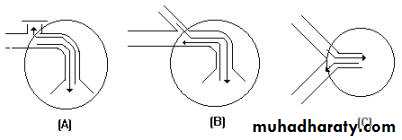
The Mapleson D consists of fresh gas inlet nearer the patient end ,a corrugated rubber tubing one end of which is connected with expiratory valve and then reservoir bag.
The system is mainly used with assisted or controlled ventilation.
During assisted or controlled ventilation there is little chance of rebreathing.
The FGF which enters during expiratory pause accumulates in the patient end and is forced during the inflation.
In spontaneous breathing during inspiration the patient will inhale the fresh gas & gas in corrugated tube depending on FGF, TV, length of expiratory pause & volume of corrugated tube.
Rebreathing can be minimized by increasing FGF two to three times the minute volume.
For an adult 15L/min FGF which seems uneconomical is required.
In some cases 250ml/kg/min require to prevent rebreathing.
The system seems to be most efficient for controlled ventilation.
Bain circuit
Introduced by Bain & Spoerel in 1972.
The Bain circuit is a modification of the Mapleson D system.It is a coaxial system in which the fresh gas flows through a narrow inner tube within the outer corrugated tubing.
Essentially, the Bain circuit functions in the same way as the T-piece, except that the tube supplying fresh gas to the patient is located inside the reservoir tube.
Fresh gases are constantly delivered very close to the patient’s mouth end.
Specifications
Length – 1.8 meters.
Diameter of outer tube –22 mm(transparent, carries expiratory gases).
Diameter of inner tube - 7 mm( carries inspiratory gas flows).
Resistance- less than 0.7 cms H2O.
Dead space – outer tube upto expiratory valve( around 500ml=TV).
Expiratory valve- called APL valve during controlled ventilation.
Flow rates- 100-150 ml/kg/min for controlled ventilation.
Average 300ml/kg/min for spontaneous ventilation.
Modifications
A bag may be added to the tail of the reservoir tube, as in the
T-piece.
Alternatively, the circuit may be attached to a block assembly with a pop-off valve and mounted directly to the common gas outlet of the anaesthesia machine. This arrangement facilitates scavenging and intermittent positive pressure ventilation.
Advantages
Can be used for children and adult-called as Universal circuit.Lightweight,minimal drag on the ETT,helps in various positions & shifting from one position to another with less risk of disconnections,away from the surgical site like head & neck surgeries, in CT scan.
Low dead space.
Low resistance to breathing.
Facilitates scavenging of waste gases.
Automatic warming of fresh gas flow as inner tube is surrounded by expired gases.( providing humidity)
Easily sterilized by Cidex.
Helps controlling pt’s ventilation during transport to RR or ICU.
Disadvantages
High fresh gas flow requirement.
As with other co-axial systems, if the inner tube becomes disconnected or breaks, the entire breathing tube becomes dead space, leading to severe alveolar hypoventilation.
Risk of rebreathing mixture of fresh gas & alveolar gas as longer pause is required to drive the alveolar gas out.


