Digital Signal Processing (DSP)
04
Z-Transform
1- Basic Definition of the Z-Transform:
The z-transform of a function x(
n
) is
defined as
:
n
n
z
n
x
z
X
)
(
)
(
So we can write that X(z) =
{x(
n
)}
There is a close relationship between the z-transform and the Fourier transform of a
discrete-time response
h
(
n
), which is defined as
n
jnw
jw
e
n
h
e
H
)
(
)
(
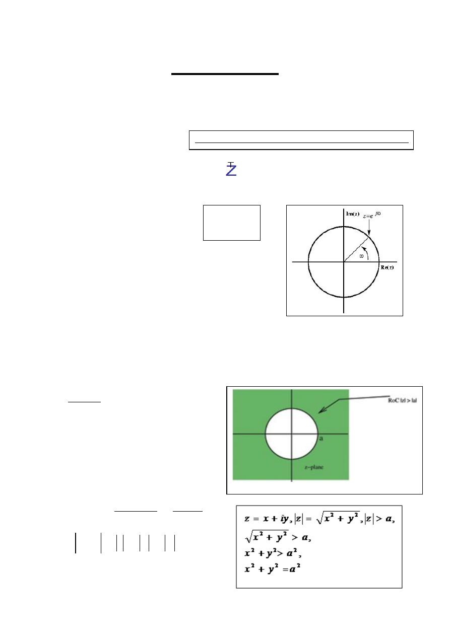
The z-plane is a complex plane with an imaginary and
real axis referring to the complex-valued variable z.
n
n
z
n
h
z
H
)
(
)
(
2- Region of Convergence
:
The ROC for a given x(n) , is defined as the range of z for which the z-transform
converges.
Example- 1: Find z-transform of
)
(
)
(
n
u
a
n
x
n
for 0 < a < 1 ?
Solution: The z-transform is given by
0
1
)
(
)
(
)
(
n
n
n
n
n
az
z
n
u
a
z
X
Which converges to
a
z
or
az
for
a
z
z
az
z
X
1
1
1
)
(
1
1
Next: Another ROC example
j
e
z
The power series for the z-transform is called a Laurent series:
Digital Signal Processing (DSP)
04
Example- 2
:
Find z-transform of
x (n) = -b
n
u (-n
–
1)
Solution: The z-transform is given by
1
)
(
)
(
n
n
n
n
n
n
z
b
z
n
x
z
X
or
1
)
(
n
n
n
z
b
z
X
1
)
(
n
n
n
z
b
z
X
1
n
n
b
z
0
1
n
n
b
z
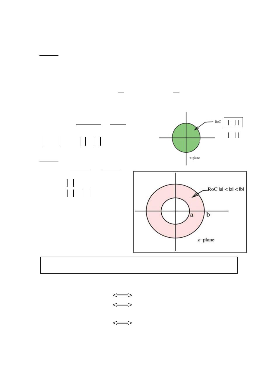
The ROC in this case is the range of values where
b
z
or
z
b
for
b
z
z
z
b
z
X
1
1
1
1
)
(
1
1
Example- 3:
x(n) = a
n
u(n) – b
n
u(-n – 1)
Solution:
Using the results of Examples 1 and 2,
2
1
2
1
)
(
ROC
ROC
ROCt
b
z
ROC
a
z
ROC
b
z
z
a
z
z
z
X
-Common area exist
for b
n
< a & a = b (ROC rings )
and for b < a (no ROC).
3- Z-Transform properties:
Linearity:
if x
1
(
n
) X
1
(z)
and x
2
(
n
) X
2
(z)
Then for a
1
& a
2
constants
a
1
x
1
(
n
) + a
2
x
2
(
n
) a
1
X
1
(z) +a
2
X
2
(z)
;
ROC
t
= ROC
x1
∩
ROC
x2
The ROC for x(n) is the intersection of the circle
i
be
z
and the circle
i
ae
z
as shown in Figure
b
z
b
z
Digital Signal Processing (DSP)
04
Uniqueness:
if x
1
(
n
) X
1
(z)
and x
2
(
n
) X
2
(z)
if x
1
(
n
)
≠
x
2
(
n
) then X
1
(z)
≠
X
2
(z)
Time Shifting:
if x(
n
) X(z)
Then x(
n
- n
0
)
X(z);
Multiplication by an Exponential Sequence:
if x(
n
) X(z)
Then a
n
x(
n
)
X(z)
with z z/a;
ROC= |a|. ROCx , so if r
L
< ROCx <r
U
|a|. r
L
< |a| ROCx <|a| r
U
|a|. r
L
< ROC <|a| r
U
Multiplication by ramp:
if x(
n
) X(z)
Then n x(n) - z {d X(z) / dz};
ROC: ROC
x
except for the possible addition or deletion of the origin or infinity.
Time Reversal
:
if x(
n
) X(z)
Then
x(-
n
) X(1/z);
ROC: 1/ROCx
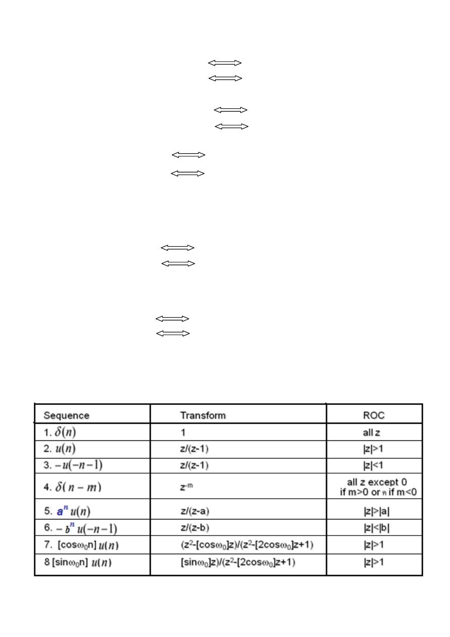
4- Some Common z-Transform Pairs:
Digital Signal Processing (DSP)
04
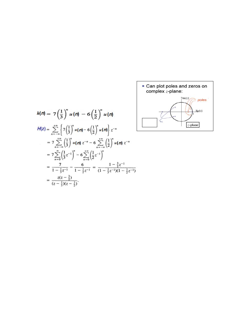
Example- 4: Find z-transform of
( ) ( )
,
( )- ( )
Solution
( )
, * ,
( )- ( )+-|
for
| |
0
* ,
( )- ( )+1 |
0
* ,
( )- ( )+1 |
[
(
(
)
*] |
[
(
(
⁄ *
(
⁄ *
4(
⁄ *
(
⁄ *
5
)
]
ROC=?
H.W.-1:
( ) ( )
,
( )- ( )
H.W.-2:
( )
,
( )- ( )
Digital Signal Processing (DSP)
00
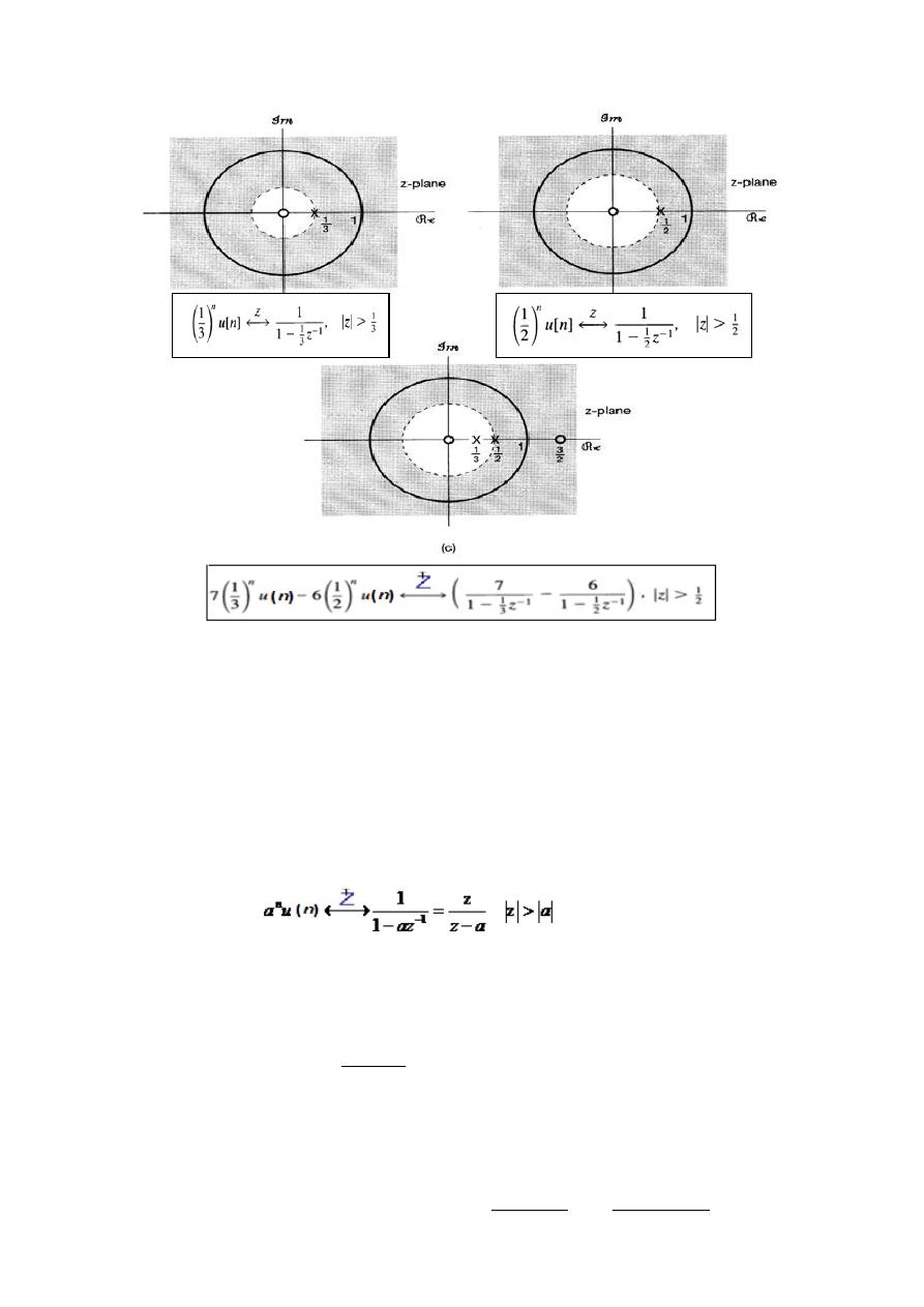
5- Poles and Zeros
When H(z) is a rational function, i.e., a ration of polynomials in z, then:
The roots of the numerator polynomial are referred to as the zeros
of H(z), and
The roots of the denominator
polynomial are referred to as the
poles of H(z).
Example- 5
:
For the response
Zeros
Digital Signal Processing (DSP)
04
6- The Inverse Z-Transform
•
Less formal ways sufficient most of the time
–
Inspection Method
–
Partial Fraction Expansion
–
Power Series Expansion
Inspection Method
–
Make use of known z-transform pairs such as
Inverse Z-Transform by Partial Fraction Expansion:
• Assume that a given z-transform can be expressed as
• Apply partial fractional expansion
N
k
k
k
M
k
k
k
z
a
z
b
z
X
0
0
s
m
m
i
m
N
i
k
k
k
k
N
M
r
r
r
z
d
C
z
d
A
z
B
z
X
1
1
,
1
1
0
1
1

Digital Signal Processing (DSP)
04
• First term exist only if M > N
– B
r
is obtained by long division
• Second term represents all first order poles
• Third term represents an order s pole
– There will be a similar term for every high-order pole
•
Each term can be inverse transformed
by inspection
• Coefficients are given as
Easier to understand with the following examples:
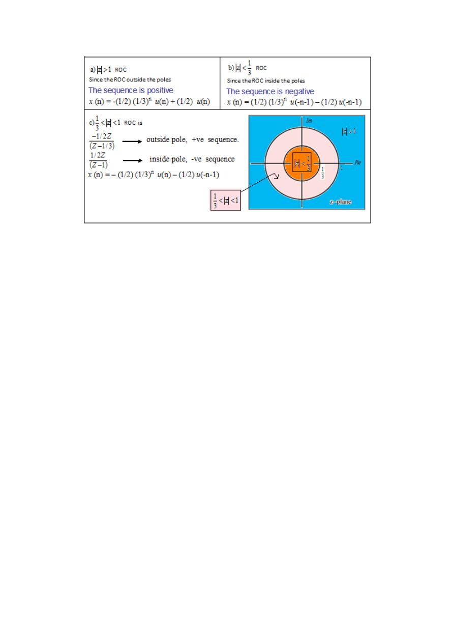
Example- 6: Find the inverse Z-Transform of
Solution
1
3
/
1
)
(
Z
B
Z
A
Z
F
2
1
)
3
/
1
(
3
1
1
)
(
lim
2
1
)
1
(
3
1
3
/
1
)
(
lim
Z
Z
Z
F
B
Z
Z
Z
F
A
1
2
/
1
3
/
1
2
/
1
)
(
Z
Z
Z
F
,
So
1
)
2
/
1
(
3
/
1
)
2
/
1
(
)
(
Z
Z
Z
Z
Z
X
s
m
m
i
m
N
i
k
k
k
k
N
M
r
r
r
z
d
C
z
d
A
z
B
z
X
1
1
,
1
1
0
1
1
k
d
z
k
k
z
X
z
d
A
1
1
1
1
1
!
1
i
d
w
s
i
m
s
m
s
m
s
i
m
w
X
w
d
dw
d
d
m
s
C
1
3
1
)
,
3
1
)
,
1
z
a)
:
ROC
for
1
4
3
2
Z
c
Z
b
Z
Z
Z
z
X
)
(
1
3
/
1
3
/
1
1
4
3
1
)
(
2
Z
F
Z
Z
Z
Z
Z
Z
X
Digital Signal Processing (DSP)
04
7-Properties of ROC of the Z-Transform
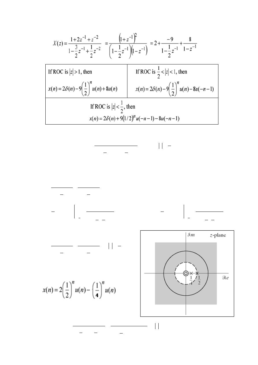
• ROC is a ring or disk centered at the origin.
• Fourier transform converges absolutely if ROC includes the unit circle.
• ROC contains no poles but is bounded by poles.
• If the sequence is finite in length, ROC is the Entire z-plane
except possibly z = 0 and z = ∞.
• If the sequence is right-sided, ROC is an outer disk.
• If the sequence is left-sided, ROC is an inner disk.
• If the sequence is double-sided, ROC is a ring.
• ROC is a connected region.
Example- 7: Find the inverse Z-Transform of
Digital Signal Processing (DSP)
04
Example- 8: find the inverse Z-Transform of
- Order of numerator is smaller than denominator (in terms of z
-1
)
- No higher order poles
and
• ROC extends to infinity, - Indicates right sided sequences
Example- 9: Find the inverse Z-Transform of
2
1
z
:
ROC
2
1
1
4
1
1
1
1
1
z
z
z
X
1
2
1
1
2
1
1
4
1
1
z
A
z
A
z
X
1
4
1
2
1
1
1
4
1
1
1
4
1
1
1
z
z
X
z
A
2
2
1
4
1
1
1
2
1
1
1
2
1
1
2
z
z
X
z
A
2
1
z
2
1
1
2
4
1
1
1
1
1
z
z
z
X
1
z
1
2
1
1
1
2
1
2
3
1
2
1
1
1
2
1
2
1
2
1
z
z
z
z
z
z
z
z
X
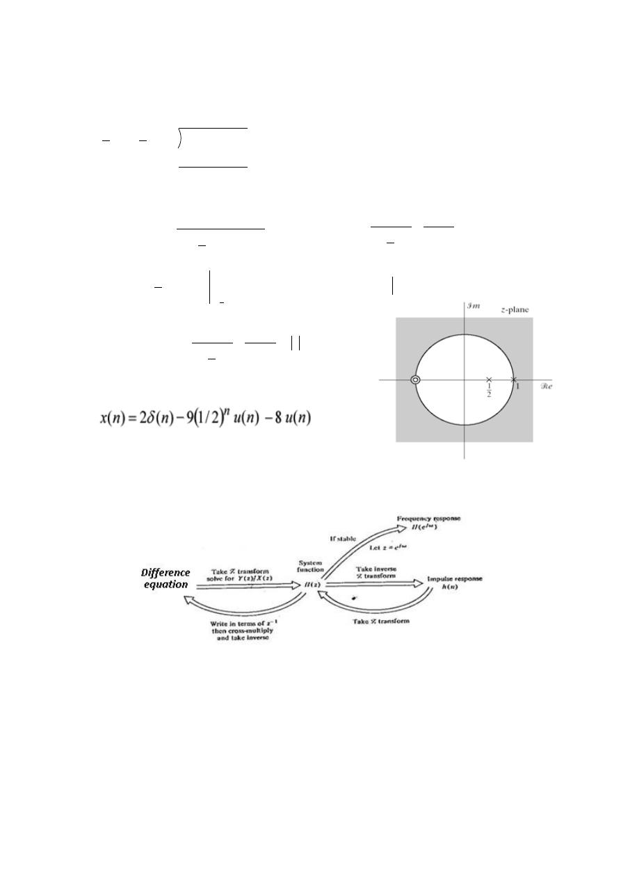
Digital Signal Processing (DSP)
04
• Long division to obtain B
o
or
• ROC extends to infinity, Indicates right-sides sequence
8- Relationships between System Representations:
Relationships between difference equation, system function, impulse
response, and frequency response for stable causal systems represented
by linear, constant coefficient difference equation.
Example- 10: Using Z-Transform, find the solution (for
) to the following
linear constant coefficient difference equation:
1
5
2
3
2
1
2
1
2
3
2
1
1
1
2
1
2
1
2
z
z
z
z
z
z
z
1
1
1
1
2
1
1
5
1
2
z
z
z
z
X
1
2
1
1
1
2
1
1
2
z
A
z
A
z
X
9
2
1
1
2
1
1
1
z
z
X
z
A
8
1
1
1
2
z
z
X
z
A
1
z
1
8
2
1
1
9
2
1
1
z
z
z
X

Digital Signal Processing (DSP)
44
( )
( )
( ) .
/
With initial conditions
( ) ( )
Solution:
Taking the Z-transform of both sides gives
( )
* ( )
( )+
* ( )
( )
( )+
Substituting in the initial conditions and rearranging gives
( ) [
]
And dividing by
0
1
( )
.
/
. /.
/ ( )
By partial fraction expansion, we can write
( )
Taking the inverse z-transform, the difference equation is
( ) 6
(
*
(
*
7 ( )
H.W: Try to solve it in time domain and compare the results.
Example- 11: Given that
( )
( )
(
)
Represents a causal system, find a
difference equation realization and the frequency response of the system.
Solution: Since the system is causal, first write H(z) in terms of negative power of z
( )
( )
( )
( )
(
)
Now Cross Multiply:

Digital Signal Processing (DSP)
44
( )(
) ( )(
)
Taking the inverse transform yields the following difference equation:
( ) ( ) ( ) ( ) ( )
The frequency response can be obtained by letting
becomes
(
)
( )
(
)
|
→
(
)
(
)
(
)
(
) | (
)|
. ⌊
(
)
|
(
)|
√( )
( )
√( )
( )
(
)

Digital Signal Processing (DSP)
44
DIGITAL FILTER DESIGN
Methods Of System Representation:
1-Difference equation realization:
2-Transfer function:
If a
o
=1 & other a
k
's=0, then the filter is FIR, otherwise it is IIR.
3-The impulse response:
h(n) =
{ H(z)}
Digital Filter Specifications
1-Frequency Response
a-attenuation in pass band and stop band
b-cutoff frequency and roll off frequencies.
2- The magnitude and/or the phase (delay) response are specified for
the design of a digital filter for most applications.
• In some situations, the unit sample response or the step response
may be specified.
• In most practical applications, the problem of interest is the
development of a realizable approximation to a given magnitude
response specification
3- Phase response can be corrected by cascading the filter with an all-
pass section!!!
M
k
k
N
k
k
k
n
x
b
k
n
y
a
0
0
)
(
ˆ
)
(
ˆ
General form D.E.
N
k
k
k
M
k
k
k
z
a
z
b
z
X
z
Y
z
H
0
0
Digital Signal Processing (DSP)
44
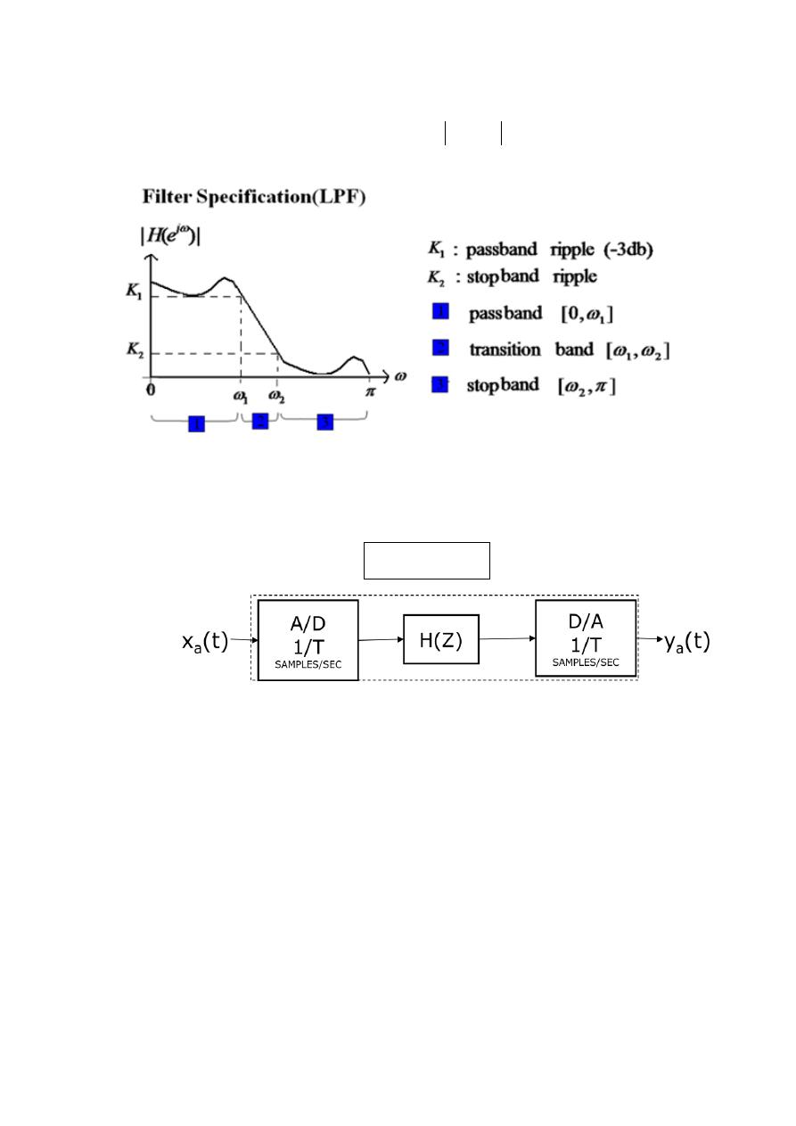
For example, the magnitude response
j
e
H
of a digital lowpass
filter may be given as indicated below
•
As a result, filter specifications are given only for the frequency range 0≤ ω ≤ π
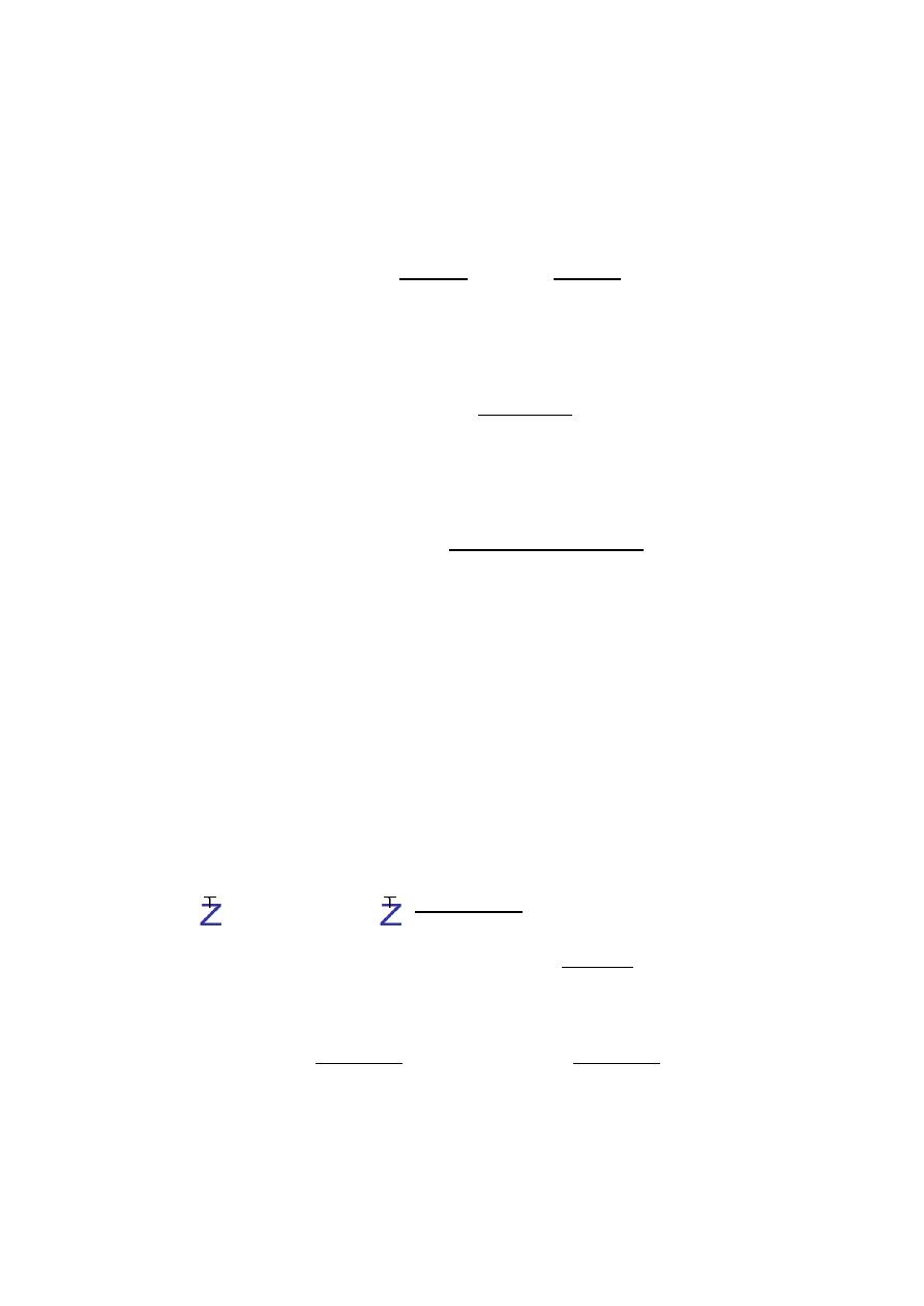
To SIMULATE an analog filter, a discrete-time filter H(z) is used in the
analog
– to digital – H(z) – digital – to – analog structure shown in Fig. 2.
Equivalent analog filter
Fig. 2 Simulation of an analog filter
IIR FILTER DESIGN:
Several different techniques for designing H(z).
1-
Numerical Method
s.
2-
Biliner Transformation
Method
.
3-
Impulse-Invariant Method
.
H(z)
Discrete time filter
Digital Signal Processing (DSP)
40
1- THE DESIGN BY USING NUMERICAL SOLUTIONS OF
DIFFERNTIAL EQUATIONS:
Simulates a continuous-time linear filter specified by the following
differential equation:
∑
( )
∑
( )
This filter has input x
a
(t) and output y
a
(t) and can be characterized
by its system function H
a
(s) by taking the Laplace transform
( )
∑
∑
Suppose that we approximate the derivatives by backward differences.
The first backward difference
( )
, - is defined by
( )
, ( )-
,
(
)
(
)-
Higher-order backward difference are found by
( )
, ( )-
( )
,
( )
* ( )+-
Using the kth-order differences as approximations to the derivatives in
Eq.(4-4) we have
∑
(
)
[
( )
] ∑
(
)
,
( )
-
The above equation represents a numerical approach for obtaining
( )
,
the sampled version of
( )
.
The Z-transform of the first
and k
th
-order difference are given below:
*
( )
, ( )-+ 2
, ( ) ( )-
3 ( )(
)
*
( )
, ( )-
+
( ) 4
5
The Z-transform of both sides
∑
,
-
(
) ∑
,
-
(
)
The transfer function is easily seen to be:
Digital Signal Processing (DSP)
44
( )
( )
( )
∑
,
-
∑
,
-
Comparing with the Equation of
( )
, we see that H(z) can
be obtaind by replacing S by
(
)
, that is
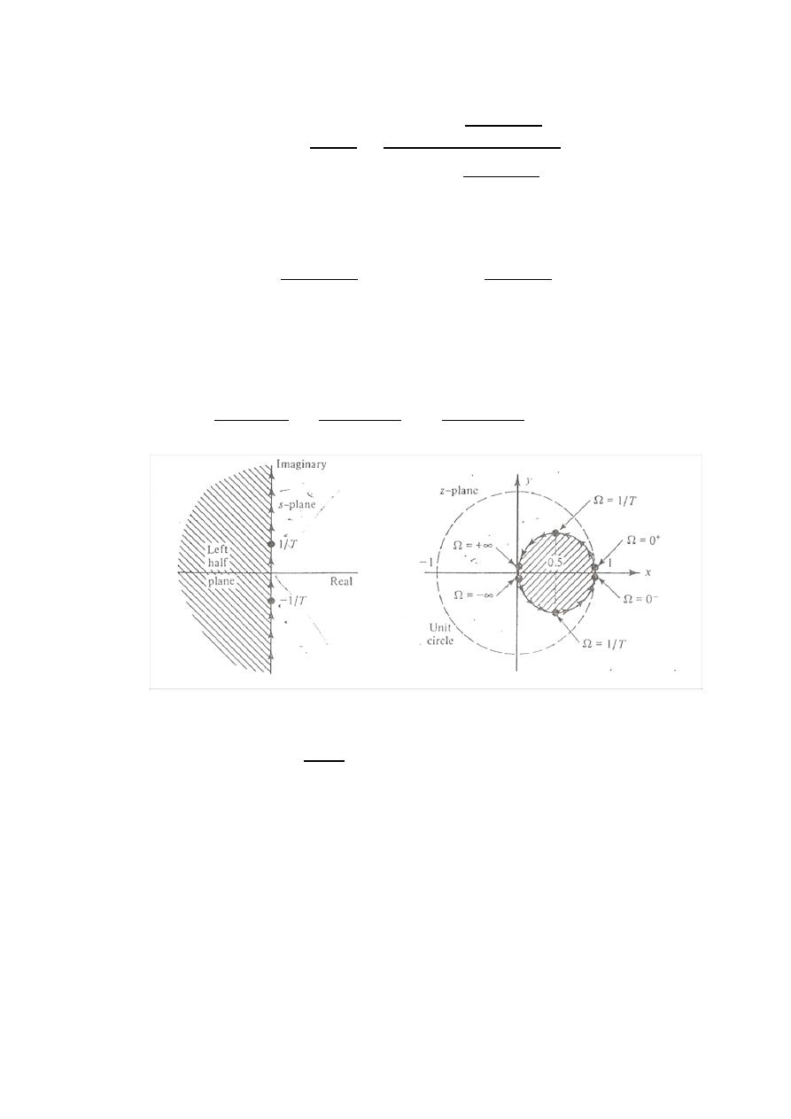
As the frequency response for the analog system is
obtained by letting s = j
Ω
, it is of interest to look at the
image in the z-plane of the j
Ω
axis of the s-plane which is
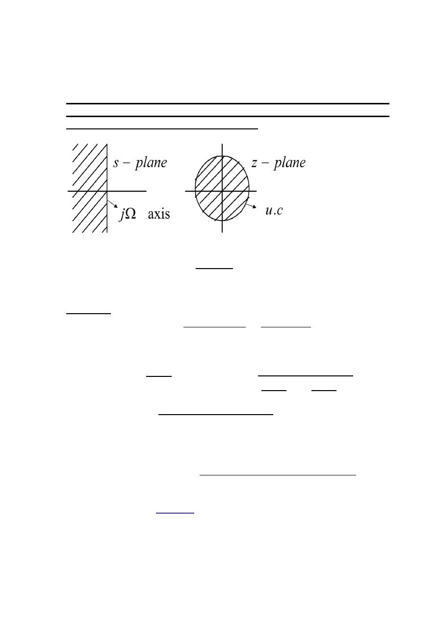
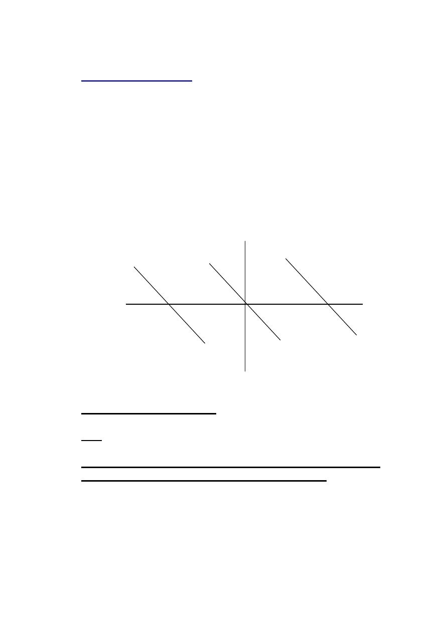
In the above figure, the image of the j
Ω
axis of the s-plane in the z-plane
for the mapping
is shown
It is easy to see that
x
(the real part of z) and y (the imaginary part of z)
are related by
Completing the square in the above equation gives the following
equation:
( )
Thus, the image in the z-plane of the j
Ω
axis of the S-plane is a circle of
radius 1/2 , as shown in the figure.
Digital Signal Processing (DSP)
44
The frequency response of the digital filter is obtained by evaluating
H(z) on the unit circle,
. The shape of the equivalent
frequency response of the H(z) would not be similar to that of
( )
.
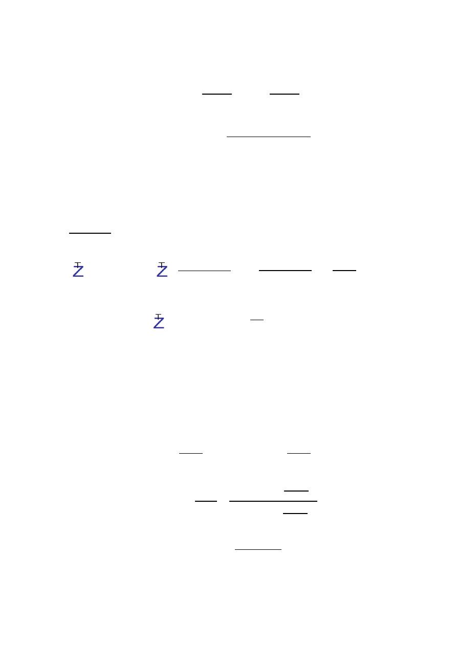
To preserve the shape of the frequency response, we like to have the
transformation from analog filter to digital filter take the
j
Ω
axis of
the s-plane into the unit circle in z-plane.
Example -1: An analog filter with system function
( )
( )( )
,
a- Find the H(z) using numerical method
b- Plot the frequency response for f
s
= 5 bps
?
Solution:
( )
( )( )
By numerical method
a- Since,
Then
( )
[
]
[
]
Or
( )
b-
f
s
= 5 bps
,
(
) ( )
→
(
)
|
(
)
|
⌊
(
)
Digital Signal Processing (DSP)
44
H.W.: Suppose we are given the following differential equation:
∑
( )
∑
( )
The first forward difference
( )
, ( )- is defined by
( )
, ( )-
, ( ) ( )-
and the n
th
forward difference is obtained by successive first forward
differences.
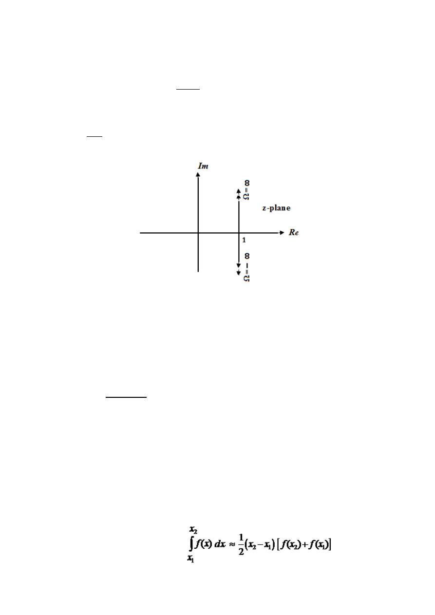
(a)- Find the mapping from the s-plane to the z-plane necessary to obtain
the digital transfer function directly from the analog transfer function.
(b)- Using such transformation, find the z-plane image of s = jΩ as Ω goes
from
.
Solution:
(a)- The z-transform of the first forward difference is given by
0
(
)
,
( )
-1
2
, ( ) ( )-
3
2
, ( ) ( )-
3
( )
( )
The z-transform of the k
th
- order forward difference is
0
(
)
,
( )
-1
.
/
(
)
Using the k
th
- order forward differences as approximations to the derivatives in the
given differential equation, we have
∑
(
)
[
( )
] ∑
(
)
,
( )
-
The z-transform of both sides
∑
( )
,
-
(
) ∑
( )
,
-
(
)
The transfer function is easily seen to be
( )
( )
( )
∑
(
)
,
-
∑
(
)
,
-
Using Laplace transform on the given differential equation, we can write
( )
∑
∑
Digital Signal Processing (DSP)
44
Comparing the above to equations we see that the mapping from the
s-plane to z-plane is
(b)- for s = jΩ as Ω goes from
.
and for s = jΩ
,
we get
The locus of points in the z-plane as
varies is shown below
2- IIR FILTER DESIGN BY BILINEAR TRANSFORMATION
Design Concept:- Using a first-order differential equation
( )
( )
x(t) …………….(1)
The transfer function H
a
(s) can be written as
( )
( )
The fundamental theorem of integral calculus allows us to write
( ) ∫
( )
(
) ( )
Since Eq.(3) holds for any t with any t
0
, we let t = nT and t
0
= (n-1)T
to get
( ) ∫
( )
,( ) - ( )
( )
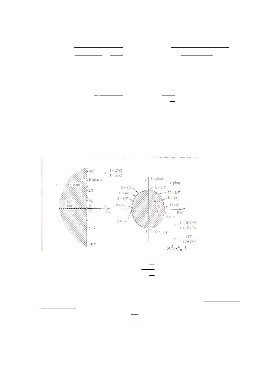
Using the trapezoidal rule

Digital Signal Processing (DSP)
44
To approximate the integral and by assuming equality, a recursive
relationship for determining
( ) can be found from Eq. (4) as follows:
( )
,( ) - (
* *
( )
,( ) -+ ( )
From Eq. (2)
( )
( )
( ) ( )
Now the differential equation evaluated in t = nT:
( )
( )
( ) ( )
&
(( ) )
(( ) )
(( ) ) ( )
Substitute (7) & (8) into (5) to obtain a difference equation for the
equivalent discrete-time system. Then
( ) (
* {
( )
( )
(( ) )
(( ) )}
,( ) -
The previous expression can be expressed in the following form
(
*
( ) (
*
(( ) )
{ ( ) (( ) )}
The z-transform of the previous equation is
(
* ( ) (
)
( )
* ( )
( )+
Transfer function of the equivalent digital filter is
( )
(
)
(
* (
*
( )
(
)
.
/ .
/
( )
(
)
(
)
(
)
( )
( )
( )
Y z
H z
X
z
Digital Signal Processing (DSP)
44
( )
(
)
(
)
( )
(
)
(
)
Comparing H
a
(s) of Eq. (2) and H(z) it can be seen that H(z) can be
obtained from H
a
(s) by using the following mapping relation:
(
)
(
)
or
…….(18)
This is the bilinear transformation. The image of the jΩ axis from the s-
plane in the z-plane is shown in the Figure below. The bilinear
transformation given in Eq.(18) has the following properties:
(1)- The entire jΩ axis of the s-plane goes into the unit circle of the z-plane.
(2)- The left half side of the s-plane is transformed inside the uint circle of
the z-plane.
The image in the z-plane of the j
Ω
axis of the s-plane for the mapping
Therefore a stable analog filter would be transformed into a stable
digital filter. While the frequency responses of analog filter and
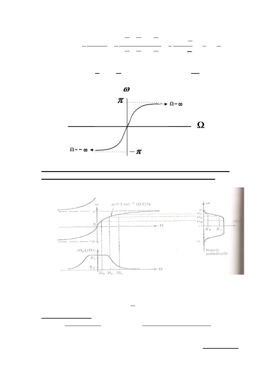
digital filter have the same amplitudes. There is a nonlinear
relationship between corresponding digital and analog frequencies.
If
s = j
Ω, then
Digital Signal Processing (DSP)
44
(
*
(
*
.
/
(
*
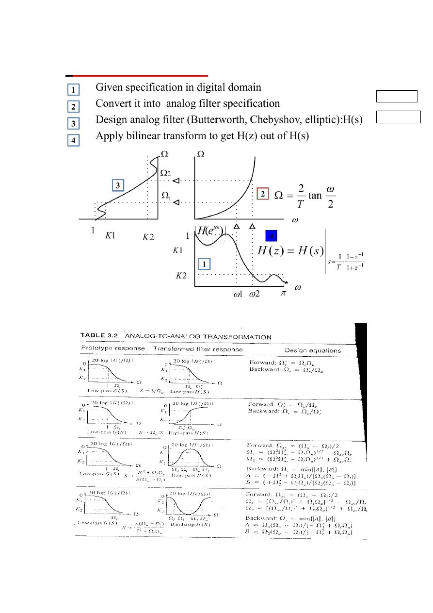
Nonlinear mapping introduces a distortion in the frequency
axis called frequency warping seethe following Figure:
The digital frequency will have a critical frequency
given by
(
). The equivalent critical frequency becomes
(
)
WHICH WILL GIVE
ONLY IF
(
)
is small that
(
)
is approximately equal to
(
)
This warping of the critical frequency will be compensated for in the
design procedure using the bilinear transformation by prewarping
.
Digital Signal Processing (DSP)
44
*
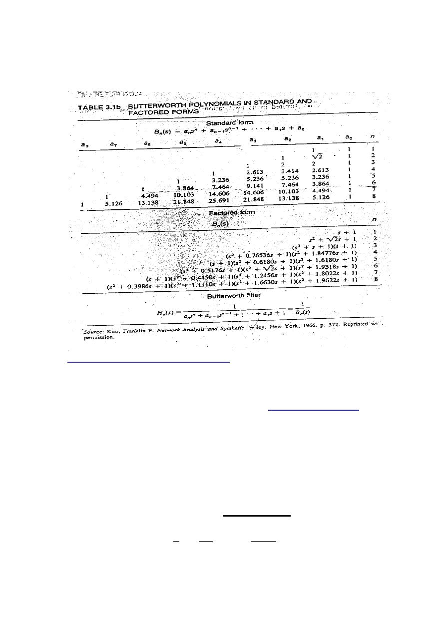
IIR Filter Design Procedure
TABLE 3-2
TABLE 3.1
Digital Signal Processing (DSP)
44
Example (LP Butterworth Filter)
Design and realize a digital low-pass filter using the bilinear
transformation method to satisfy the following characteristics:
(a) Monotonic stopband and passband(
Butterworth Filter
).
(b) -3.01dB cutoff frequency of 0.5
rad.
(c) Magnitude down at least 15 dB at 0.75
rad.
Solution:-
The design procedure is that of using the bilinear
transformation on an analog prototype and consists of the
following steps:
Step1. Prewarp the critical digital frequencies
using T=1 sec to get

Digital Signal Processing (DSP)
40
2
Step2. Design an analog low-pass filter with critical
frequencies
and
that satisfy
|
(
)|
|
(
)|
A Butterwirth filter is used to satisfy the monotonic
property and has an order
and critical frequency
Determined by the following equations :
⌈
[(
) (
)]
(
)
⌉
(
)
We get
⌈
[(
) (
)]
.
/
⌉
(
)
Therefore the required prewarped analog filter using the
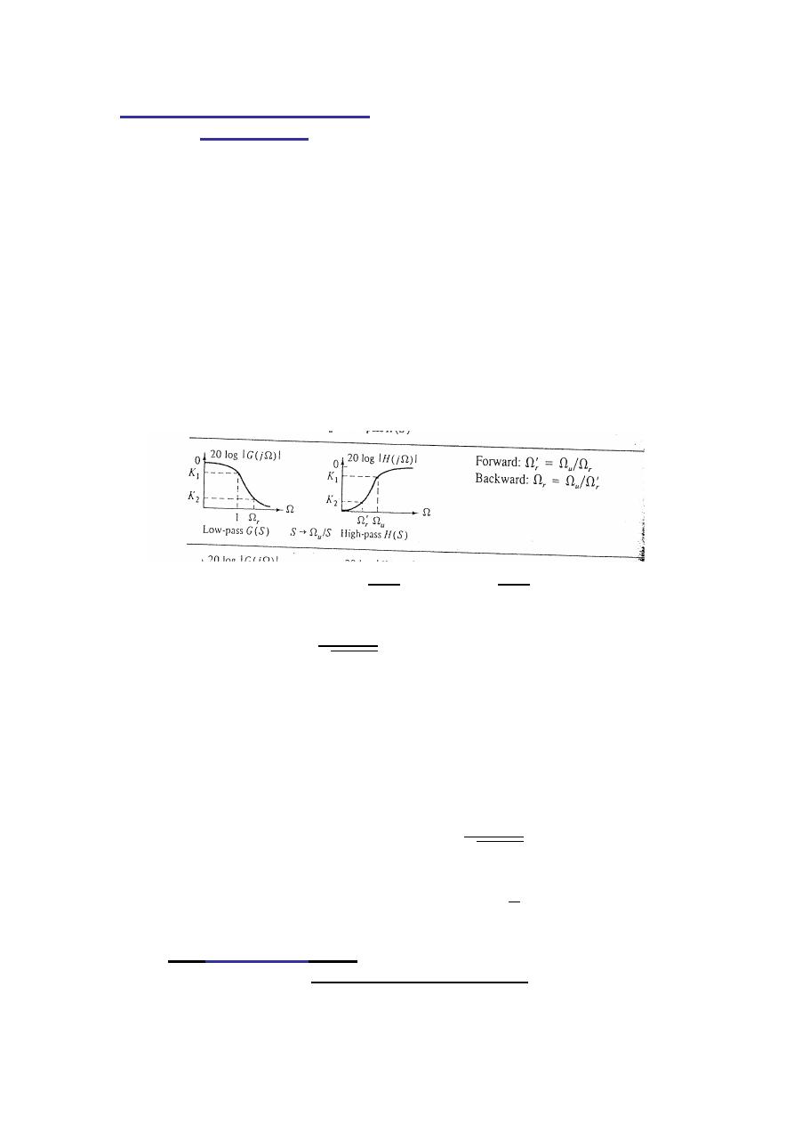
Butterworth Table 3.1 and low-pass to low pass
transformation from table 3.2 is
( )
√
|
( )
√ ( )
√
Step3. Applying the bilinear transformation method(T=1) to
satisfy the given digital requirements:
( )
( )|
6
(
)
(
)
7
Digital Signal Processing (DSP)
44
( )
[
(
)
(
) ]
√ [
(
)
(
) ]
( )
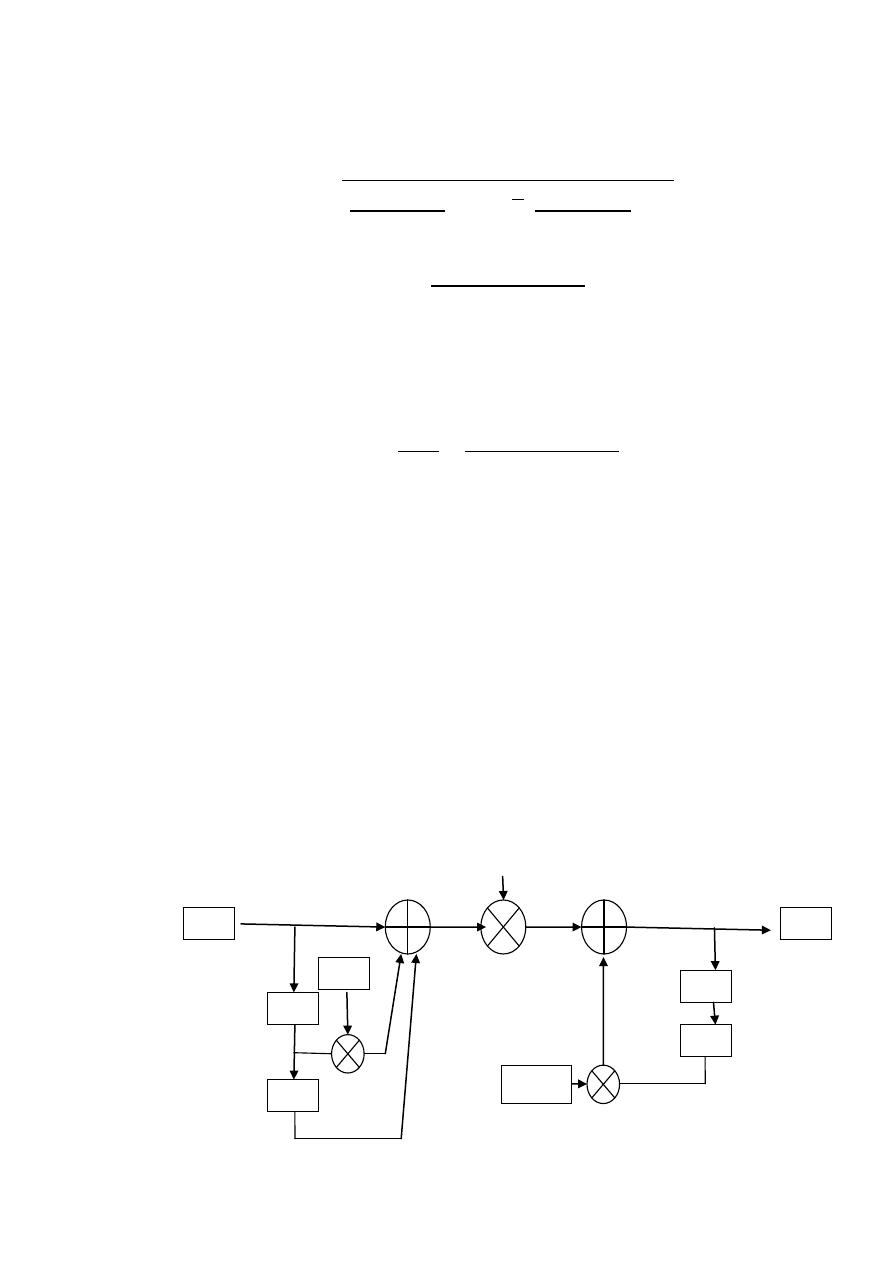
This digital filter can be realized by specification of a
difference equation obtained from the transfer function
H(z) given by
( )
( )
( )
Cross multiplying gives:
( ),
- ( ),
-
And taking the inverse Z-transform we find
, ( ) ( )- , ( ) ( ) ( )-
By rearranging and scaling. y(n) can be realized by the
following difference equation:
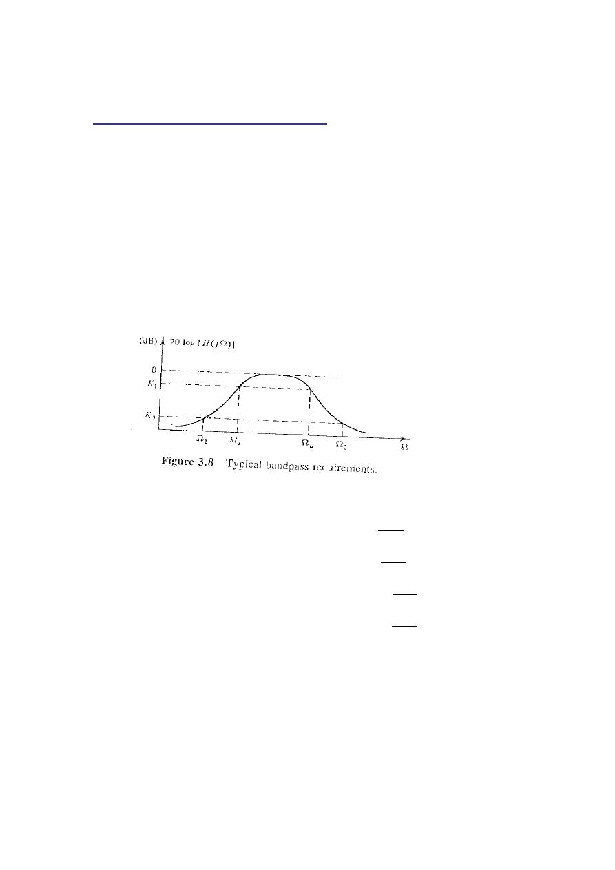
( ) , ( ) ( ) ( )- ( )
z
-1
z
-1
z
-1
z
-1
-0.172
2
x(n)
y(n)
Digital Signal Processing (DSP)
44
Example (BP Butterworth Filter)
Design a digital band-pass filter representing an analog one with
the following specifications:
(a) Stop band attenuation of at least 20dB at warpped
frequencies of 20Hz and 45kHz.
(b) -3 dB lower and upper cutoff bilinear warpped
frequencies of 50Hz and 20kHz.
(c) a monotonic frequencies.
Solution:-
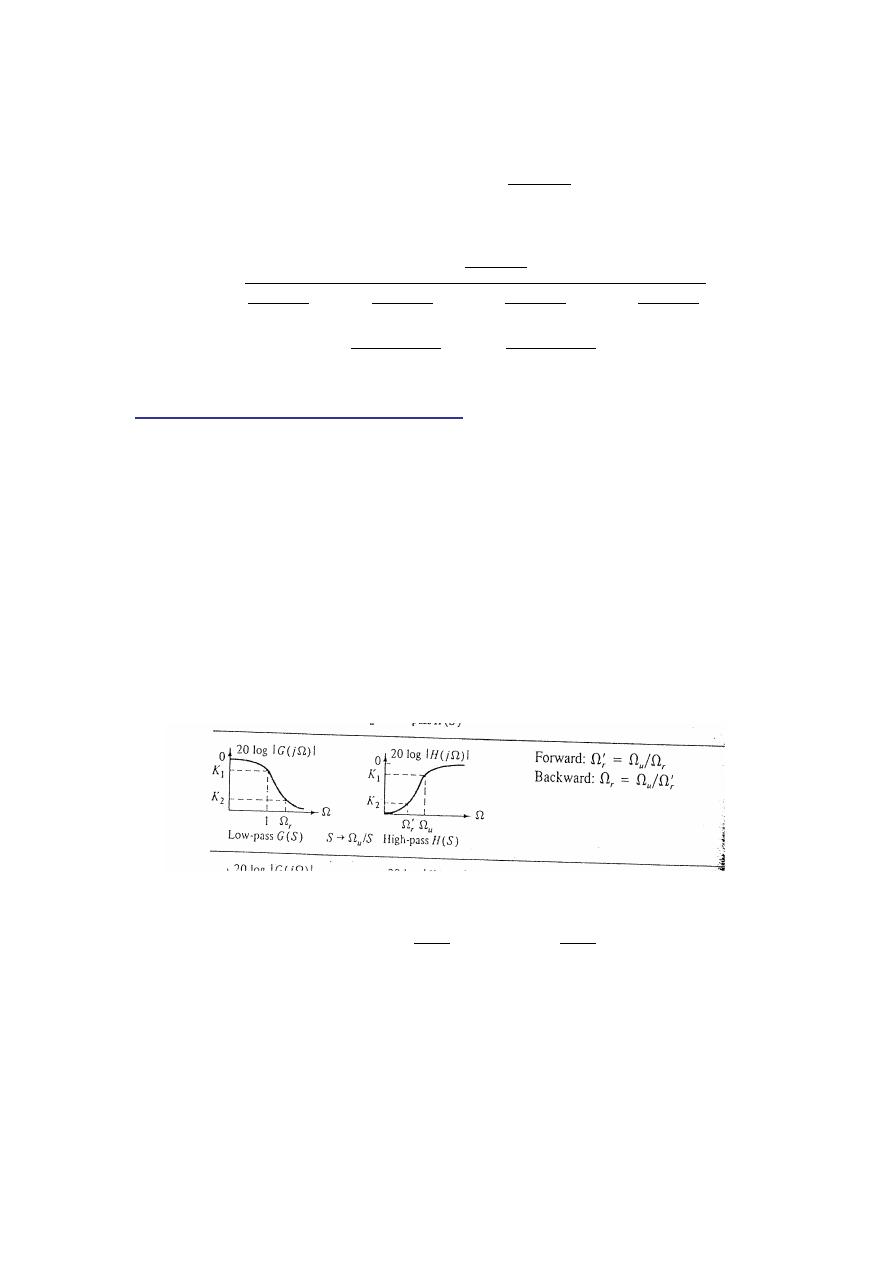
The desired frequency response is shown on the right
From table (3.2) we see
( )
( )
( )
( )
The Backward equation then gives the
for a normalized
Low pass prototype.
,(| |) (| |) -
From table (3.2) USING (
)we see

Digital Signal Processing (DSP)
44
(
)
,
(
-
(
)
,
(
-
A=2.5053, B=2.2545
The most critical value
is the minimum of the two, that
is,
,(| |) (| |) -=2.2545
The low-pass Butterworth filter of order
can then be
easily calculated from the following equations :
⌈
[(
) (
)]
(
)
⌉
We get
⌈
[(
) (
)]
.
/
⌉ ⌈ ⌉
from the Butterworth Table 3.1b and n=3 we have the low-
pass prototype as
The required analog-to-analog transformation (table 3.2) is
determined from
as
6
(
)
(
)
7
(
)
( ) then is finlly seen to be
( )
[
(
)
]
[
(
)
]
[
(
)
]
( )
Digital Signal Processing (DSP)
44
Applying the bilinear transformation method(T=1) to satisfy
the given digital requirements:
( )
( )|
6
(
)
(
)
7
( )
[
(
)
(
)
]
[
.
/
.
/
]
[
.
/
.
/
]
[
.
/
.
/
]
[
.
/
.
/
]
[
(
)
(
)
]
[
(
)
(
)
]
Example (HP Butterworth Filter)
Design a digital filter representing an analog one with the
following specifications:
(a) Pass all signals of bilinear warpped frequencies greater
than 200rad/sec with no more than 2dB of attenuation.
(b) Stop band attenuation of greater than -20 dB at warpped d
frequencies less than 100rad/sec.
(c) a maximally flat IIR response.
Solution:-
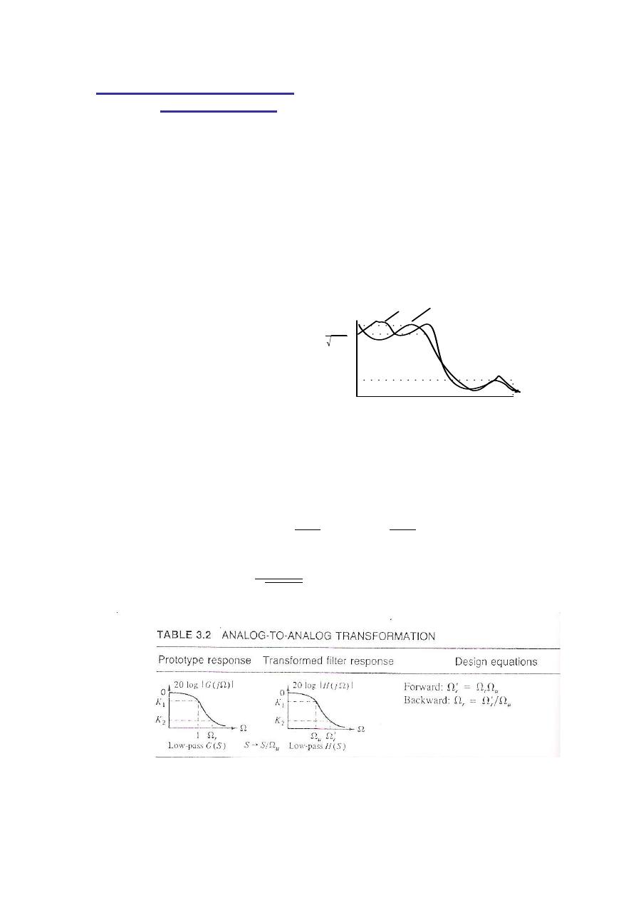
The desired frequency response is shown on the right
From table (3.2) we see
The Backward equation then gives the
for a normalized
Low pass prototype.
=200/100=2

Digital Signal Processing (DSP)
44
The low-pass Butterworth filter now has the following
specifications
The order
of the filter is determined as follows
⌈
[(
) (
)]
(
)
⌉
We get
⌈
[(
) (
)]
.
/
⌉ ⌈ ⌉
(
*
(
*
from the Butterworth Table 3.1b and n=4 we have the
NORMALIZED low-pass filter as
(
) (
)
The low-pass filter
prototype
( )
( )⌉
0
1
( )
.(
)
(
) / .(
)
(
) /

Digital Signal Processing (DSP)
44
To get desired HPF apply LP TO HP( analog-to-analog
transformation (table 3.2))
( )
( )⌉
0
1
( ) then is finlly seen to be
( )
.(
)
(
) / .(
)
(
) /
Applying the bilinear transformation method(T=1) to satisfy
the given digital requirements:
( )
( )|
6
(
)
(
)
7
( )
((
[
(
)
(
)
]
)
(
[
(
)
(
)
]
) ) ((
[
(
)
(
)
]
)
(
[
(
)
(
)
]
) )
Digital Signal Processing (DSP)
44
Example ( Chebyshev LPF)
Design a
Chebyshev LPF
representing an analog one with the
following specifications:
(a) Acceptable pass-band ripples of 2dB.
(b) Cut off frequency of 40 rad/sec.
(c) Stop band attenuation of 20 dB or more at 52 rad/sec.
Solution:-
The desired frequency response is shown on the right
The general approach is to first change the requirements to
those of a low-pass unit bandwidth PROTOTYPE, design
such a LPF , and then apply a LP to LP Transformation to
that PROTOTYPE.
From table (3.2) we see
√
even
odd
1
2
2
K
ε2
1
1
K1
1

Digital Signal Processing (DSP)
44
The Backward equation then gives the
for a normalized
Low pass prototype.
=52/40=1.3 rad. /sec
The low-pass filter now has the following specifications
√
(
*
The low-pass
Chebyshev
filter of order
can then be
easily calculated from the following equations :
⌈
0. √
/1
4
√
5
⌉ where √
,
| ( |
√
(
*
√
0. √
/1
4
√
5
⌈
[( √
)]
( √
)
⌉

Digital Signal Processing (DSP)
44
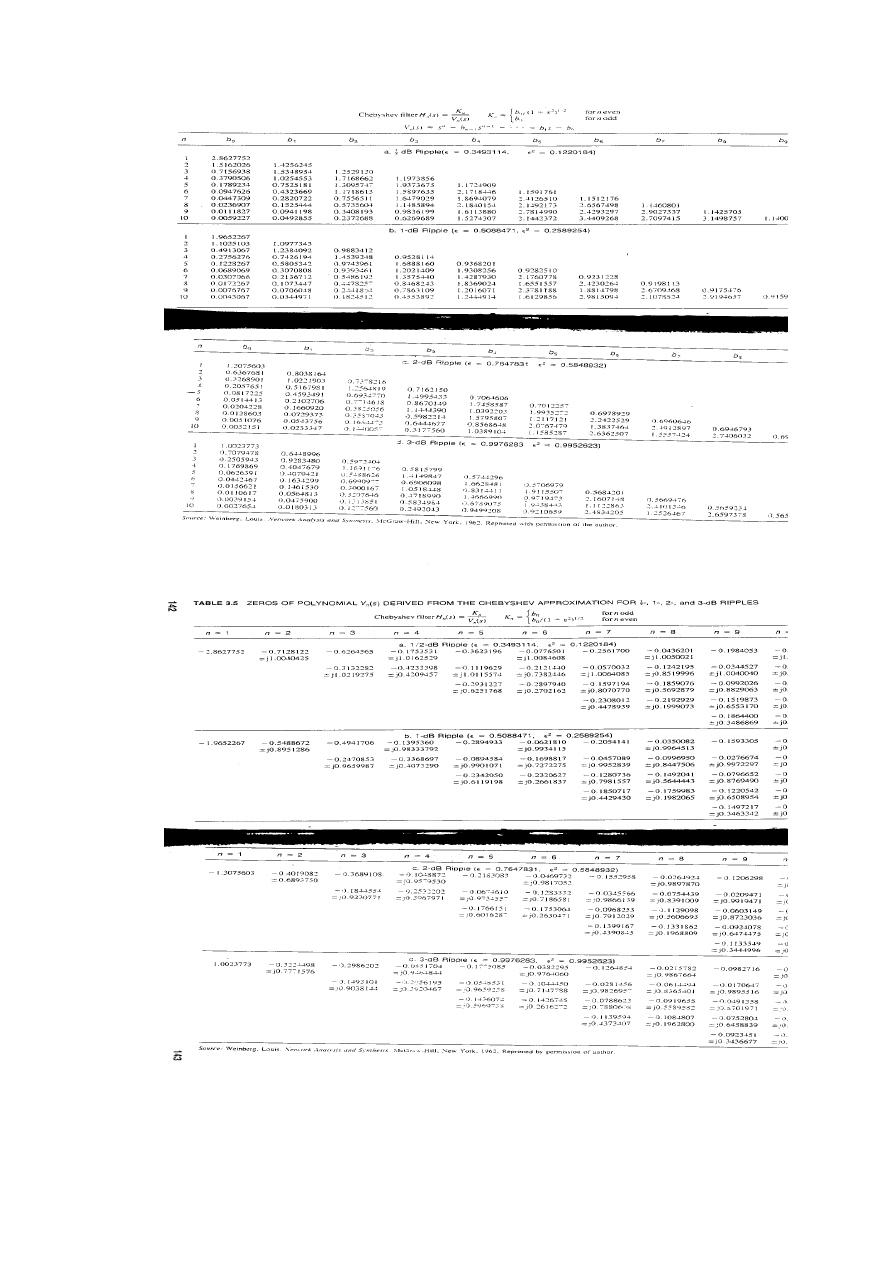
Using the 2dB ripple part of Table 3.4
( )
( )
{
(
)
( )
for n=5, and the fact that since n is odd, we have the desired
Chebyshev unit bandwidth low-pass filter as
( )
( )
( )⌋
( )
( )
( )
( )
( )
( )
( )⌋
(
)
(H.W)
Design a digital filter having a 1-dB cut off frequency at 75 Hz
and greater than 20-dB attenuation for
. Find H(z) that
will satisfy the above prewarpped specifications for :
(a) Butterworth .
(b) Chebyshev approximations.
Digital Signal Processing (DSP)
40
Digital Signal Processing (DSP)
44
3.IIR Filter Design by Impulse Invariant Method
( )
↔ ( )
↔ ( )
↔ ( )
Example
Find the H(z) corresponding to the impulse invariant design a
sample rate of 1/T samples/sec. for an analog filter H
a
(s)
specified as follows:
( )
( )
Solution:
The analog system's impulse invariant response is obtained
by taking the inverse Laplace transform of H
a
(s) to give h
a
(t)
as
( )
( )
The corresponding h(n) is then given by
( )
( ) (
)
( )
And therefore the discrete-time filter has the following Z-
transform
( ) , ( )- , (
)
( )-
Digital Signal Processing (DSP)
44
FIR Filter Design
In the previous sections, digital filters were designed to give
a desired frequency response magnitude without regard to
the phase response. In many cases a linear phase
characteristic is required throughout the pass-band of the
filter to preserve the shape of a given signal within the pass-
band.
Assume a filter with frequency response
(
) | (
)|
(
)
(
) ( )
Why linear phase filter ?
The linear phase filter did not alter the shape of
original signal, simply translated it by an amount
.
If the phase response had not been liner , the output
signal would have been a distorted version .
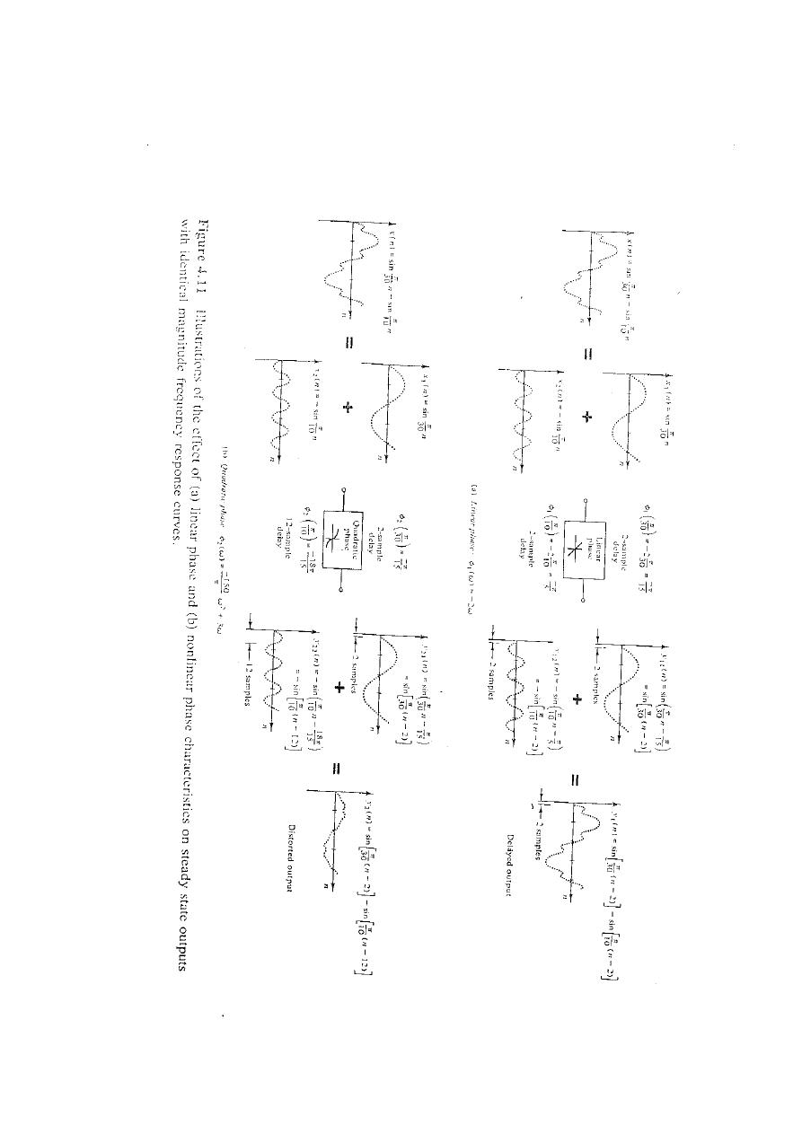
In Fig.4.11 the responses of two different filters to the
same input( a sum of two sinusoidal signals) is
presented. The filters have the same magnitude
frequency response but differ in their phases as one
has linear and the other a quadratic phase. For the
filter with liner phase, the sinusoidal components

Digital Signal Processing (DSP)
44
each go through a steady state phase change, but in
such a way that the output signal is just a delayed
version of the input while the quadratic phase filter
causes phase shifts in the two sinusoidal signals
resulting in an output that is a distorted version of
the input signal.
It can be shown that a casual IIR filter cannot
produce a linear phase characteristic and that only
special forms of casual FIR filters can give linear
phase. This result is clarified in the following
theorem.
Theorem : If h(n) represents the impulse response of
a discrete-time system, a necessary and sufficient
condition for linear phase is that h(n) have finite
duration N, and that it by symmetric about its
midpoint.
Digital Signal Processing (DSP)
44

Digital Signal Processing (DSP)
44
THE DESIGN Concept:-
For a casual FIR filter whose impulse response
begins at zero ends at (N-1) , h(n) must satisfy the
following:
h(0)=h(N-1) &
h(n)=h(N-1-
n) ……for n=0,1,2,……,N-1
for this condition the general shapes of h(n) that give liner phase.
(
) ∑ ( )
(
) ∑ ( )
for N an even number.
The summation can be broken into
two parts as follows:
(
) ∑ ( )
( )
∑ ( )
Letting m=N-1-n ( n=N-1-m) in the second sum gives
∑ ( )
∑ ( )
( )
But
( )
( ), and the summation can be
reversed to give
(
) ∑ ( )
(
)
∑ ( )
(
)
( )

Digital Signal Processing (DSP)
44
Combining yields
(
) ∑ ( )
(
)
∑ ( )
(
)
( )
(
) ∑ ( )
(
)
,
( )
-
(
)
(( ) )
∑ ( )
(
)
,
(
)
(
)
-
By factoring we are able to separate
(
)
into two part
as follows:
(
)
(( ) )
∑ ( )
(
)
*
,
( )
-+
Linear phase Magnitude
(
) (
*
There for, if the sum remains positive,
(
)
has a
linear phase with slope
.
/
, for N an odd number ,
a similar derivation leads to
(
)
(( ) )
{ (
* ∑ ( )
( )
*
,
( )
-+ }
Digital Signal Processing (DSP)
44
DESIGN of FIR filters using windows:
The easiest way to obtain an FIR filter is to simply truncate
the impulse response of an IIR filter . If
( ) represents the
impulse response of a desired IIR filter, then an FIR filter with
impulse response h(n) can be obtained as follows:
( ) {
(
)
In general,
( ) can be thought of as being formed by the
product of
( ) and a " Window function" ( ) , as
follows:
( )
( )
(
)
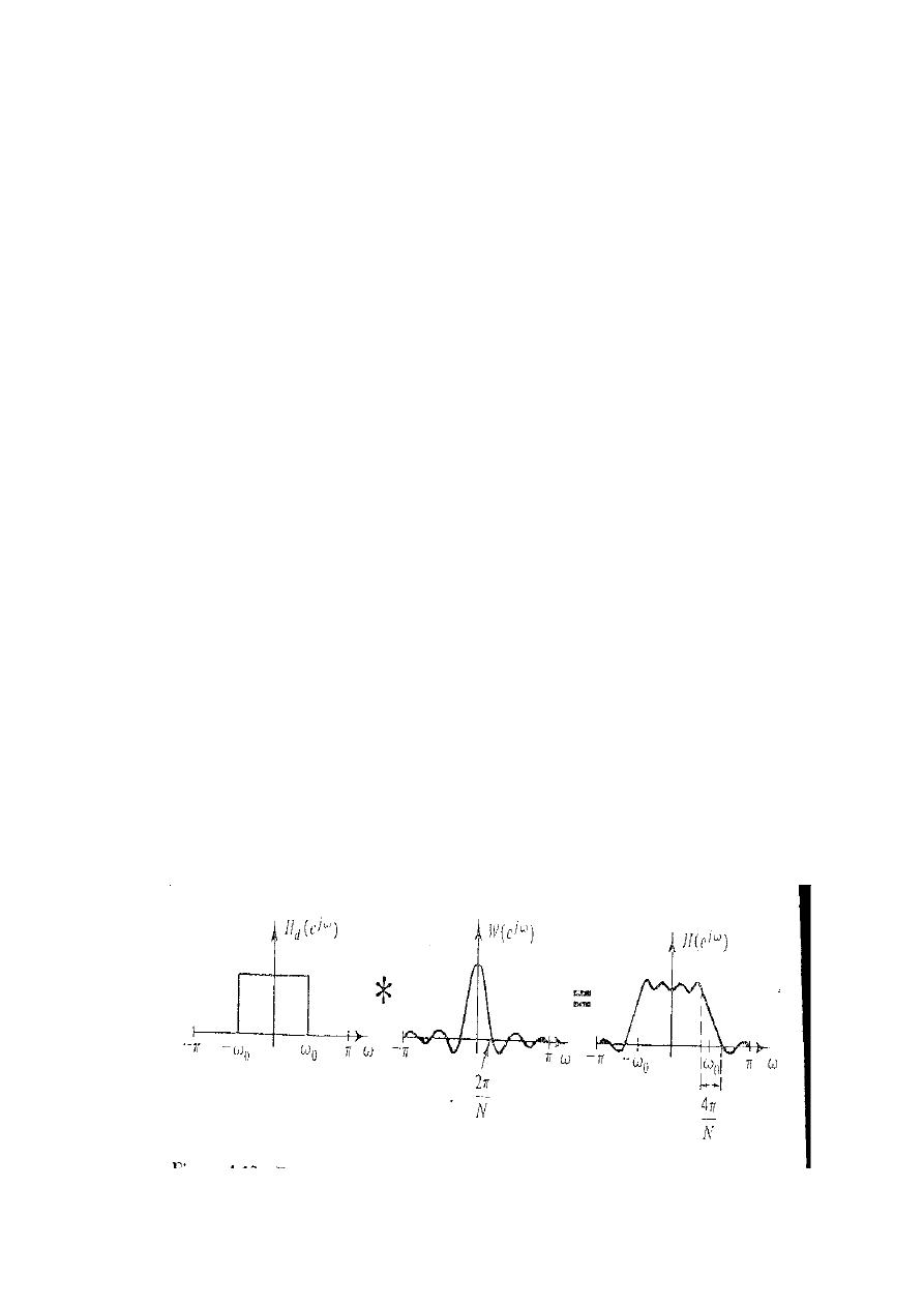
The frequency response of the resulting filter is the
convolution of
(
)
(
)
(
)
For example, if
(
)
represents an ideal low-pass
filter with cutoff frequency
and ( ) is a
rectangular window positional about the origin, the
(
)
is shown blow

Digital Signal Processing (DSP)
44
DESIGN PROCEDURE:-
An ideal low-pass filter with linear phase of slope
– and cutoff
can be characterized in the
frequency domain by
(
)
{
| |
|
| | |
Taking the inverse Fourier transform
( )
,
( )
-
(
)
A casual FIR filter with impulse response
( )
can be
obtained by multiplying
( )
by a window
beginning at the origin and ending at N-1 as follows:
( )
,
( )
-
(
)
(
)
For h(n) to be a linear phase filter,
must be
selected so that the resulting h(n) is symmetric .
As
,
( )-
( )
is symmetric about n=
and the
window symmetric about n=(N-1)/2 , a linear phase
filter results if the product is symmetric . This
requires that
( )

Digital Signal Processing (DSP)
44
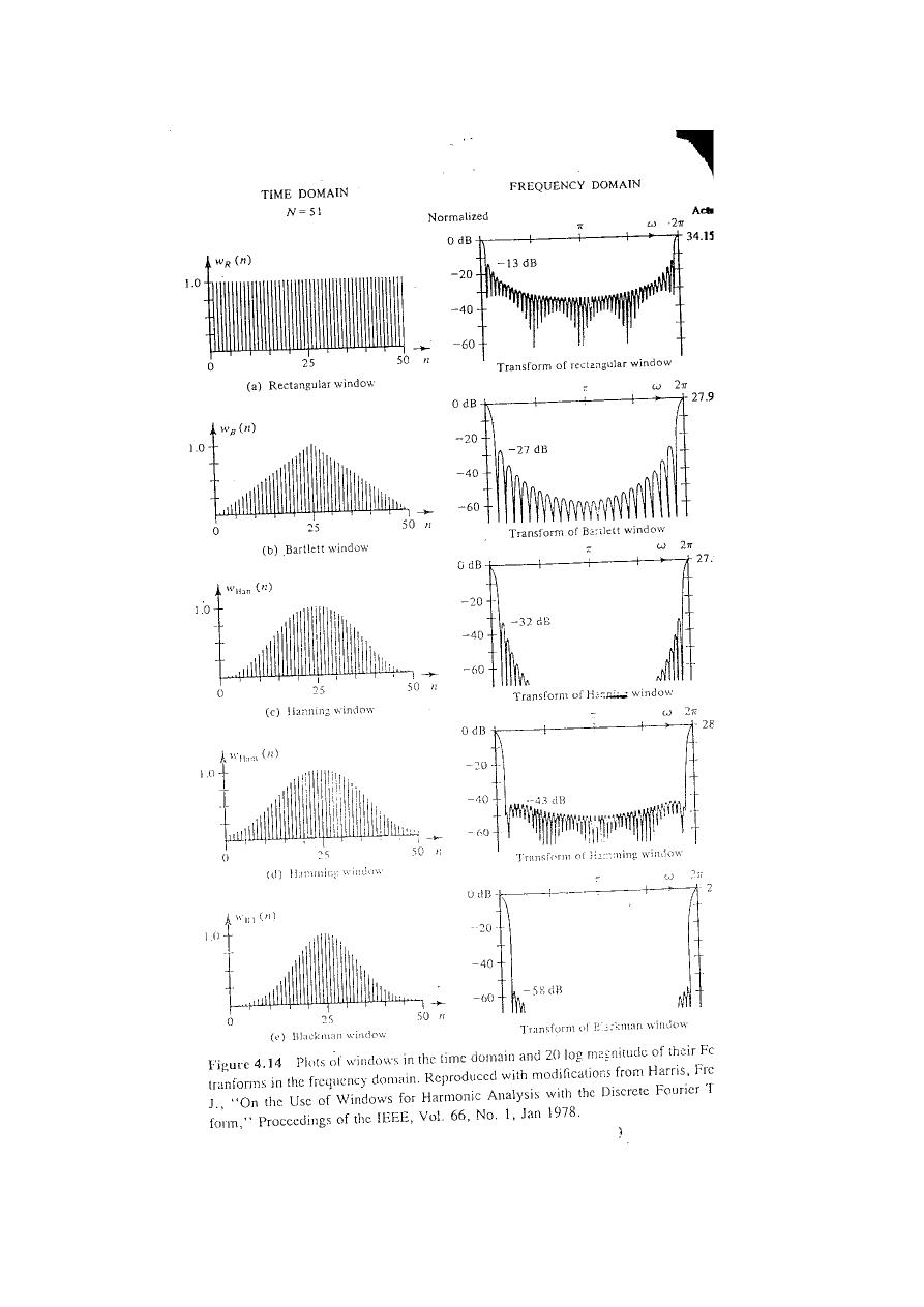
Some of the most commonly used windows are the
rectangular, Bartlett, Hanning, Hamming, Blackman, and
Kaiser windows. These are defined mathematically as
follows:
Rectangular:
( )
2
Bartlett:
( )
{
(
)
(
)
(
)
Hanning :
( )
{
2 0
13
Hamming:
( )
8 0
1
Blackman:
( )
8 0
1 0
1
Kaiser:
( )
{
*
[.
/
.
/
]
+
,
.
/-
Where
( ) is the modified zero order Bessel function of the first kind given by
(
)
∫
( ) ( )
Plots of the windows and their Fourier transform magnitudes (in decibels) are
shown in Fig 4.14 for N=51.
Digital Signal Processing (DSP)
40

Digital Signal Processing (DSP)
44
Design table for FIR low-pass filter design
Window type
Transition width
Minimum
stop-
band attenuation
K
Rectangular
-21dB
2
Bartlett
-25dB
4
Hanning
-44dB
4
Hamming
-53dB
4
Blackman
-74dB
6
Kaiser
Variable
This table although a crude approximation may be used to design a FIR LPF
from (k
1,
k
2,
w
1
,w
2
) , the following example describe this technique :
Example :- Design a low-pass digital filter to be used in an { A/D- H(z)- D/A}
structure that will have a -3dB cutoff of
rad./sec and an attenuation of 50dB
at
rad./sec. The filter is required to have linear phase and the system will
use a sampling rate of 100 samples/sec.
Solution:-
The digital specifications obtained are as follows:
( )
( )
Step 1- To obtain a stop-band attenuation of
– 50dB or more,( from the above
table ) a Hamming, Blackman, or Kaiser window could be used. The Hamming
window is chosen (k=4)
Step 2- The approximate number of points needed to satisfy the transition
band requirement can be found for
(
) (
)
To obtain an integer delay the next odd number (N=55) is selected.
Step 3- select the liner phase of slope
and cutoff
Thus giving a trial impulse response for a window as
( )
,
( )
-
(
)
(
)
For Hamming window
( )
0
1
( )
0
(
)
1
.
/
*
6
7
+
( )
,
(
)
-
(
)
8
6
79
Digital Signal Processing (DSP)
44
Example ( Chebyshev HPF)
Design a
Chebyshev
digital filter representing an analog one
with the following specifications:
(a) Pass all signals of bilinear warpped frequencies greater
than 200rad/sec with no more than 2dB of attenuation.
(b) Stop band attenuation of greater than -20 dB at warpped d
frequencies less than 100rad/sec.
Solution:-
The general approach is to first change the requirements to
those of a High-pass unit bandwidth PROTOTYPE, design
such a LPF , and then apply a LP to HP Transformation to
that PROTOTYPE.
From table (3.2) we see
√
The Backward equation then gives the
for a normalized
Low pass prototype.
=200/100=2 rad. /sec
The low-pass filter now has the following specifications
√
(
*
The
Chebyshev
filter of order
can then be easily
calculated from the following equations :

Digital Signal Processing (DSP)
44
⌈
0. √
/1
4
√
5
⌉ where √
,
| ( |
√
(
*
√
0. √
/1
4
√
5
⌈
[( √
)]
. √
/
⌉
Using the 2dB ripple part of Table 3.4
( )
( )
{
(
)
( )
for n=3, and the fact that since n is odd, we have the desired
Chebyshev unit bandwidth low-pass filter as
( )
( )
( )⌋
( )⌋
( )
( )⌋
(
)

Digital Signal Processing (DSP)
44
